How to Improve Laser Cutting Efficiency: Practical Techniques for Faster and Cleaner Production
 22-09-06
WHAT ARE YOU LOOKING FOR?
Search Across Products, Blog Posts, Support Content, And Resources.

How to Improve Laser Cutting Efficiency: Practical Techniques for Faster and Cleaner Production
22-09-06

Laser cutting machines are widely used in sheet metal processing, signage, manufacturing, prototyping, and many precision production workflows. The cutting method directly affects productivity, workpiece quality, material utilization, and the final production cost. For factories and workshops that process many parts every day, improving laser cutting efficiency is not only about cutting faster—it is also about reducing idle movement, improving piercing strategy, avoiding deformation, and lowering material waste.
A high-efficiency laser cutting process depends on the cooperation of laser power, optical focusing, cutting path planning, auxiliary gas, piercing method, material support, and machine motion control. By optimizing these areas, users can improve cutting speed, reduce downtime, protect the cutting head, and achieve cleaner parts with fewer defects.
The most valuable laser cutting improvements often come from process details: reducing empty travel, controlling heat during piercing, keeping small parts stable, selecting the right hole strategy, and choosing piercing points carefully.
Laser cutting offers major advantages over many traditional undercutting and sheet processing methods. Compared with shearing, wire cutting, profiling, flame cutting, and waterjet cutting, laser cutting can deliver smooth kerfs, accurate dimensions, fast processing speed, low noise, less smoke and dust, and the ability to cut complex shapes.
For steel plates and other sheet materials, especially when processing many nested parts, the cutting route and process strategy can influence both the processing time and the material yield. A small improvement in each part can create significant savings across repeated production batches.
A laser cutting machine uses a highly concentrated laser beam to heat the material locally. The laser generator emits the beam, and the optical path system focuses it into a very small spot. In many laser cutting processes, the focused spot can reach a minimum diameter of less than 0.1 mm, creating very high energy density at the cutting point.
As the cutting head moves along the programmed path, the material absorbs the laser energy. The surface temperature rises rapidly until the material reaches its melting point and begins to liquefy. During this process, cavities form along the cutting path and the laser beam continues to move through the contour.
Auxiliary gas is an important part of the laser cutting process. Different materials and cutting goals may require different auxiliary gases. In general, auxiliary gas supports two key functions.
Cutting speed is only one part of productivity. A machine may cut quickly but still lose time through unnecessary lifting, long empty travel, repeated piercing, heat-related defects, or collisions with unstable parts. For this reason, efficient laser cutting should be understood as a complete process, not simply a higher speed setting.
| Optimization Area | Efficiency Benefit |
|---|---|
| Empty travel control | Reduces non-cutting movement time between contours. |
| Piercing strategy | Reduces overburning, heat accumulation, and repeated process delays. |
| Micro-joint placement | Prevents small parts from tipping or colliding with the cutting head. |
| Small-hole cutting control | Improves hole quality when the hole diameter approaches or falls below sheet thickness. |
| Piercing point selection | Improves edge quality and reduces rough marks on the finished contour. |
Common sheet undercutting methods include shearing, wire cutting, profiling, flame cutting, waterjet cutting, and laser cutting. Each method has its own advantages, but laser cutting is increasingly used because it supports fast processing, accurate dimensions, smoother kerfs, low noise, and complex contour cutting.
In practical production, laser cutting efficiency can be improved through process techniques that reduce unnecessary movement, control heat, and keep the workpiece stable. The following methods are especially useful when cutting many contours, thick sheets, small parts, or shapes that are prone to deformation.
Frog jumping is an empty-stroke movement method used in laser cutting. In a normal cutting sequence, the machine may finish cutting contour A, lift the cutting head to a safe height, move horizontally to contour B, lower the cutting head, and then start cutting again. The movement from A to B is called empty travel because the machine is moving but not cutting.
In traditional empty travel, the cutting head usually completes three separate movements: lift up, move flat, and lower down. This sequence creates extra non-cutting time. Frog jumping improves this by linking the lifting, movement, lowering, and reopening actions into a more continuous motion.
During frog jumping, the cutting head rises while moving toward the next contour and then lowers as it approaches the next cutting position. The motion resembles a frog jump, which is why this method is called frog jumping. By reducing the separate up-and-down time, frog jumping helps shorten empty travel and improve overall processing efficiency.
Best use case: frog jumping is especially helpful when a cutting program contains many separate contours or repeated parts, because reducing empty travel between contours can save significant total processing time.
Concentrated piercing, also called pre-piercing, is a machining process in which all piercing operations are completed before the cutting process begins. This function is not available on every laser cutting machine, but it can be valuable when cutting thicker sheets.
In a conventional process, the laser may pierce and cut contour 1, then pierce and cut contour 2, and continue this pattern across the sheet. In concentrated piercing, the machine first pierces all contours across the entire sheet, returns to the starting point, and then cuts all contours.
Although concentrated piercing can increase the total length of the machining trajectory, it can help avoid overburning around the piercing point. This is especially useful for thick plate cutting because heat can accumulate during piercing. By completing all piercings first and then returning to cut, the material around each piercing point has more time to cool.
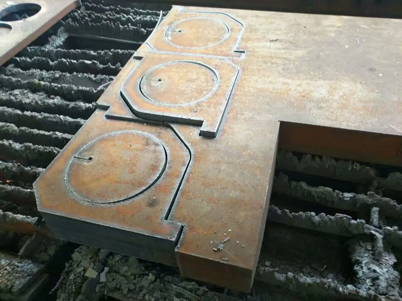
During laser cutting, the sheet is supported by serrated support bars. When a cut part is too small, it may fall through the gaps between the support bars. When a part is larger but unstable, it may tilt, buckle, or move out of balance. A high-speed cutting head may then collide with the part, causing downtime or even damage.
Micro-joints solve this problem by leaving small uncut connections between the part and the surrounding material. During programming, the closed contour is disconnected in selected places so the finished part remains attached to the sheet instead of falling or tipping immediately.
The typical micro-joint distance is about 0.2 mm to 1 mm. The correct value depends on sheet thickness, contour length, part shape, and the stability needed during cutting. In general, thicker sheets may use smaller disconnection distances, while thinner sheets may require larger disconnection distances.
Small holes are one of the most difficult features to cut cleanly, especially when the hole diameter is smaller than the sheet thickness. When the diameter is too small relative to the plate thickness, cutting becomes more difficult, the hole quality may decline, and deformation may occur.
In many production workflows, the hole diameter should be considered together with material thickness before programming the cutting path. The following table summarizes the rule-of-thumb relationship between hole size and plate thickness described in the source process notes.
| Plate Condition | Recommended Hole Diameter Guideline |
|---|---|
| Carbon steel plate ≤ 8 mm | The hole diameter should not be smaller than the sheet thickness. |
| Carbon steel plate ≤ 10 mm | The hole diameter should not be less than 1.2 times the sheet thickness. |
| Thin plate ≤ 4 mm | The hole diameter should not be smaller than the sheet thickness. |
| Plate thickness ≥ 4 mm | The hole diameter should not be less than 1.2 times the plate thickness. |
When cutting small holes in thick plates, pulse piercing can concentrate energy and burn through the sheet. However, this process can make the hole difficult to control if heat accumulation is too high. Through repeated process testing, fusion cutting can help improve this type of small-hole cutting difficulty.
For very small round holes, high-pressure nitrogen can be used to support cleaner fusion cutting. For larger round holes, oxygen may be selected according to the process requirements. The correct choice depends on material type, thickness, hole size, edge quality requirements, and the machine’s cutting parameters.
During laser cutting, the laser beam first irradiates the material continuously to form a small crater. The airflow coaxial with the laser beam removes molten material and creates a small hole. This hole becomes the starting point for contour cutting, similar to the threading hole used in wire cutting.
The piercing point matters because the laser beam often changes direction quickly when moving from the piercing stage into the contour cutting stage. If the beam direction changes too sharply over a short distance, the cut section may show a rougher surface near the starting point.
Laser cutting is a detailed process. Different materials, thicknesses, part sizes, and contour shapes require different strategies. The most effective workflow is usually built through testing, recording, and gradually improving process settings.
Improving laser cutting efficiency requires more than increasing speed. In real production, the process is complex and delicate, with many workpiece shapes, sheet thicknesses, materials, and quality requirements. Operators must use a combination of cutting techniques to improve productivity while maintaining stable part quality.
Frog jumping reduces empty travel time. Concentrated piercing helps reduce overburning on thicker sheets. Micro-joints prevent part tipping and collision. Small-hole process control improves difficult hole quality. Proper piercing point selection helps reduce rough marks on finished contours.
By applying these methods and continuously recording process results, laser cutting users can improve machine productivity, reduce material waste, and produce cleaner, more consistent parts.
Improve Your Laser Cutting Workflow
Need help selecting a laser cutting machine or improving your production workflow? Contact Thunder Laser experts for practical guidance.
Contact UsTalk To Our Experts Now!
Please leave your contact information so that we can serve you better.
LASER CUTTING EFFICIENCY FAQS
TAKE THE NEXT STEP WITH THUNDER LASER

 Stable & Consistent MachinesUnlimited ApplicationRobust After-sales SupportFactory Direct Supply