(1) Use the “Contour tracing” tool to extract the outline of the hand-painted pattern
(2) Learn to extract hand-painted pattern skills, graphic effect is better
(3) Know how to use [parameter setting], and set parameters correctly according to the design intention
Thinking training
Design thinking
(1) The unification of practicality and artistry of foreseeing products.
(2) Foresee the matching of production design and production effect.
Computational thinking
(1) Know how to make graphics and fonts on products.
(2) Know how to repeatedly draw text or graphics.
Engineering thinking
(1) Understand the time cost and material cost of different production materials.
(2) Understand the appeal of different production materials and production effects to users.
Social responsibility and moral literacy
(1) Do not make sharp objects, especially those with sharp corners, to avoid causing harm to others.
(2) In practice, you can imitate others’ works in style, and you must do improved innovation when creating.
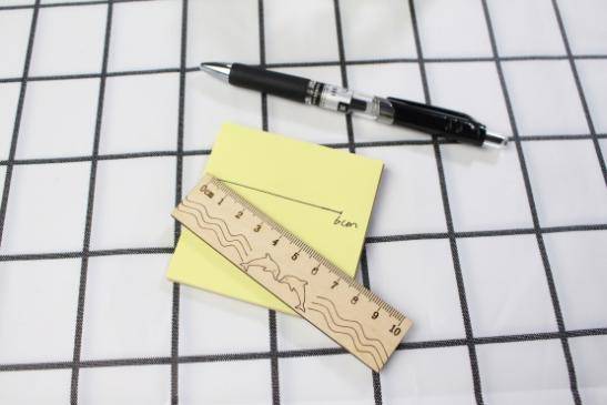
2. Application scenario
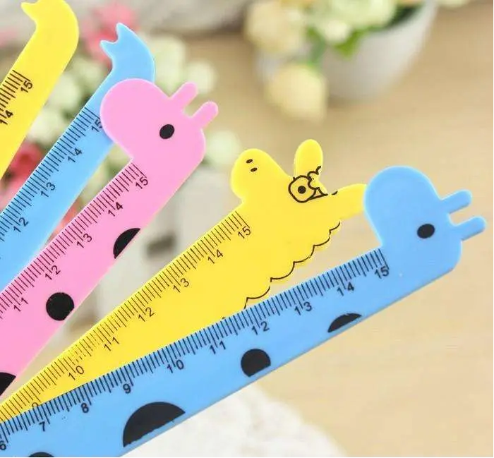
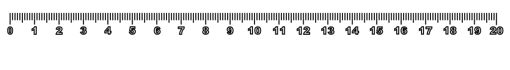
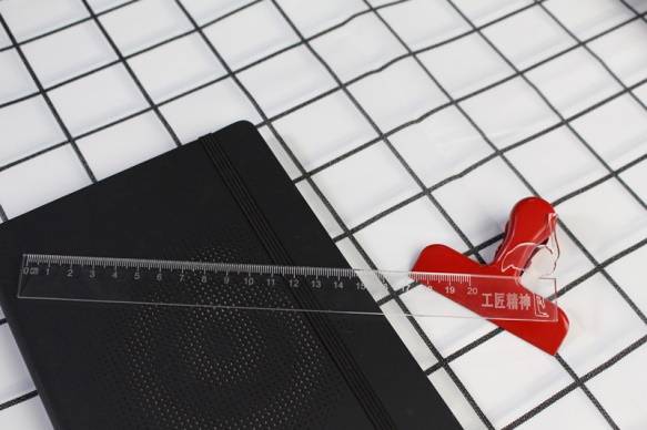
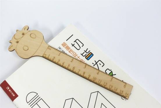
“It is all-powerful, life is straight, life is learning a good helper, pen and paper accompanied by no name.” Do you know the answer to this riddle? The answer to the riddle is the ruler, as shown in the following figure. A ruler is a tool used to measure length in life and is often used to aid drawing. There are many kinds of rulers, such as triangle rule, slide rule, soft rule, drawing rule and so on. Think about what are the elements of a ruler used every day? Play your creativity, design and make a practical and beautiful ruler.
3. Project analysis
(1) Shape of the parts: The outline can be drawn by referring to the cartoon ruler available on the market, and achieved by cutting.
(2) The content of the part: the symbol marking the scale is formed on the surface of the part material.
(3) Component size: Set component size according to demand.
(4) Use: Consider whether the ruler is used as a learning tool or a decorative item, and consider whether it needs to be waterproof, mildew proof, coloring, etc.
(5) Material selection: basswood plywood or acrylic board.
(6) Process effect: tracing effect.
4. Modeling process
1.Research and hand-drawn design
Measure
According to your project design, fill in the size of the ruler in the table below.
Measurement data
recording unit:mm
Length:
Width:
Paint
Draw a ruler design drawing in the box based on your measurement data and design elements.
2.Software drawing
After the analysis of the ruler, we can draw the ruler through 4 steps.
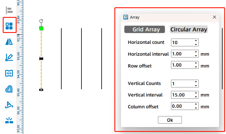
(1) Use the “Line Segment Tool” to draw the scale
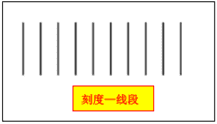
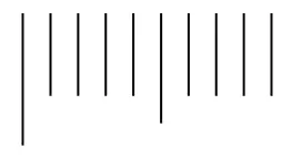
Click Line Segment Tool to draw a 3mm long line segment in the blank area of the drawing area. Click the “Rectangular Array” tool, enter “10” in the “horizontal number” column, “1” in the “Vertical number” column, and “1” mm in the horizontal spacing column in the “Rectangular Array” dialog box, and click “OK” to complete the drawing of 10 line segments, as shown in the following figure.
Click the first line segment to change its height to 5mm, then click the sixth line segment to change its height to 4mm. The top of these two lines should be aligned with the other lines, as shown in the following figure.
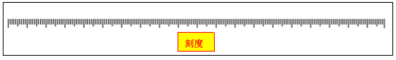
Select 10 line segments and click Rectangular Array. In the Rectangular Array dialog box, enter 10 in the horizontal number column, 1 in the Vertical number column, and 1 mm in the horizontal spacing column. Click OK. Hold it at the same level as the other line segments, and the scale is drawn, as shown in the following figure.
(2) Use the “Text Tool” to draw length values and units
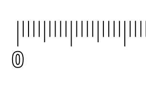
Click the “Text Tool”, move the mouse pointer under the scale, then double click and enter the number “0” in the “Draw Text” box, as shown in the following figure. Select the drawn number “0”, change its height to “3mm” and width to “2mm”, and align the center of the number “0” with the first line segment. As shownin the following figure.
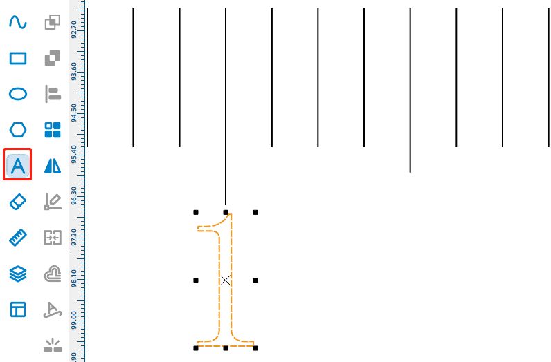
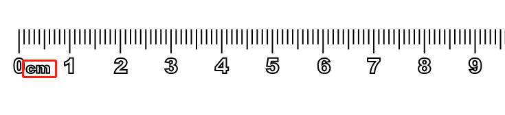
Select the number 0 and click Rectangular Array. In the Rectangular Array dialog box, enter 21 in Number of Levels and 8 mm in Horizontal Space, and click OK. 21 zeros are displayed. Double-click the second “0”, change its text number to “1”, and so on, set the last number to “20”, and align each number with the center of its corresponding line segment to complete the drawing of the length value, as shown in the following figure.
Add the unit “cm” (cm) to the right of the length value “0”. Click “Text Tool”, move the mouse pointer to the right of “0”, double click, enter “cm” in the “Draw text” box, adjust the position, and the unit can be drawn, as shown in the following figure.
(3) Draw the ruler body
Use the Rectangle Tool to draw the ruler body
Click “Rectangle Tool”, move the mouse pointer to the blank area of the drawing area, draw a rectangle, change the width of the rectangle to 240mm, change the high trim to 20mm. Select the rectangle so that the top of the rectangle is aligned with the scale, as shown in the following figure.
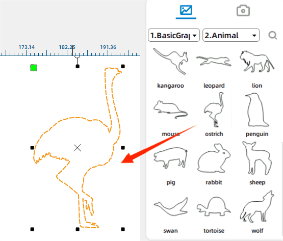
Use Select Gallery to add an Ostrich graphic
In the “Select Gallery” drop-down box, click “2. Animal Graphics”, find the “ostrich” graphics, and drag it to the blank area of the drawing area, as shown in the following figure.
Use the “eraser tool” to remove line segments
Move “ostrich” to the blank space on the right side of the ruler body, select the ostrich figure, and enlarge it to a suitable size; Click Eraser Tool. In the Eraser dialog box, enter 1. Move the mouse pointer to the intersection between the ostrich and the rectangle, and click the left mouse button to erase the line segment where the ostrich overlaps with the ruler. Click the Eraser Tool. In the Eraser dialog box, enter 0.5. Move the mouse pointer to the intersection of the ostrich and the rectangle, and click the left mouse button to erase the line segment at the intersection. Make sure the ostrich has a rectangular line segment as the reference line, divided into upper and lower parts, as shown in the following figure.
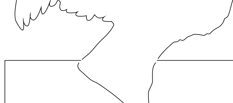
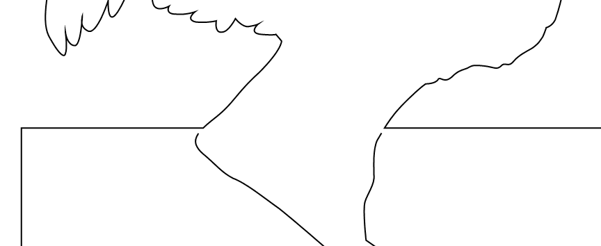
Connect graphics using the Line Segment Tool
Click “Line Segment Tool” and “Connect Line Segment” to connect the upper half of the ostrich with the rectangle to form a closed figure, as shown in the following figure.
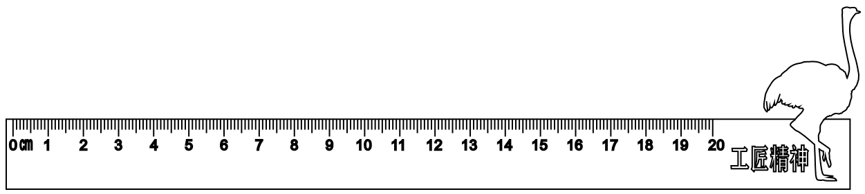
Use the Text Tool to enter text content
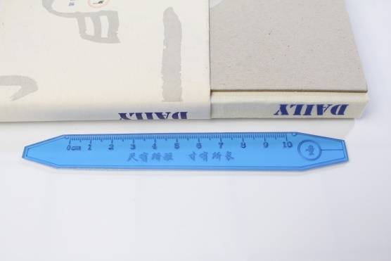
Click the “Text Tool”, move the mouse pointer between the scale and the ostrich, double click, enter the word “craftsman spirit” in the “Draw text” box, and click “OK” to draw the figure of the ostrich ruler, as shown in the following figure.
(4)Process pattern design
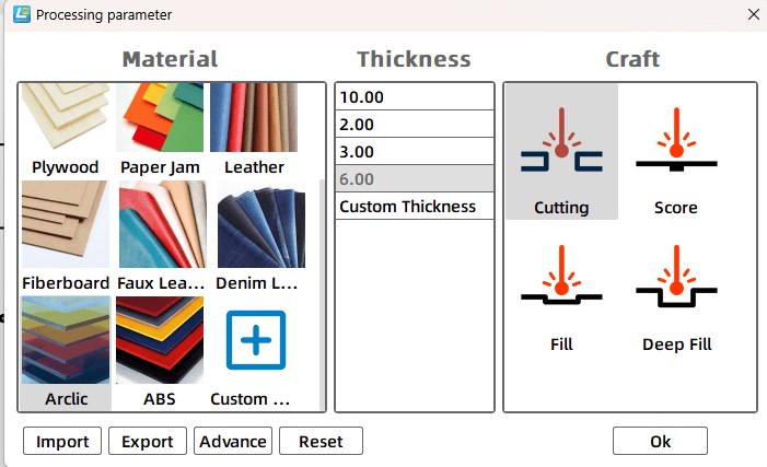
As shown inthe following figure, select the text object, set it as the “yellow light carving” process layer, double-click the corresponding process layer, and the “Processing parameters” dialog box will pop up. Set the processing material to acrylic plate, the process to shallow carving, and the processing thickness to 0.1mm.
Select the ostrich object, scale and scale unit in the rectangle, set them as the “Red Tracing” process layer, double-click the corresponding process layer, the “Processing parameters” dialog box will pop up, set the processing material to acrylic plate, the process to tracing line, and the processing thickness to 0.1mm.
Select the outline object of the ruler body, double-click its corresponding “Black cut” layer, set the processing material to acrylic, the process to cut, and the processing thickness to 3mm.
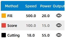
Finally, drag the process layer and adjust the process sequence to shallow carving → tracing → cutting, as shown in the following figure.
Thinking and debugging
(1) Pay attention to select different objects for parameter debugging, experience the effect of parameter Settings such as scale tracing line, ruler surface text, thinking and debugging cartoon graphics, you can enter the “engraving parameters” dialog box, fine-tune the parameters, so that the production effect is optimized.
(2) Pay attention to the appearance of the cartoon graphics and the effect debugging of the internal cutting parameter values.
5. Display of finished products
The finished product is shown in the following figure.
6. Extension exercise
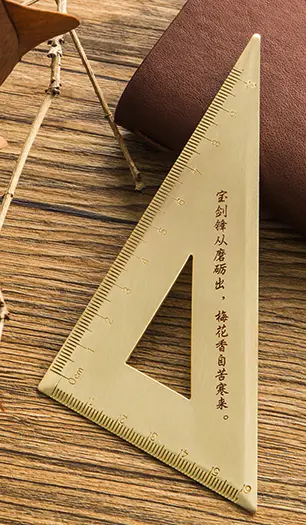
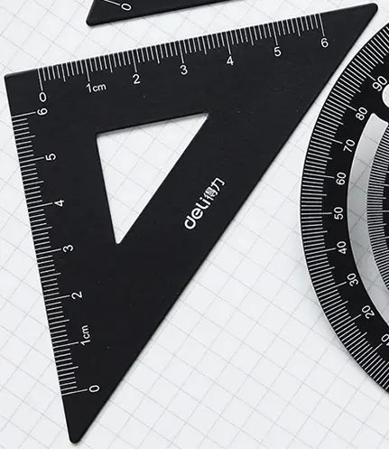
Refer to the sample shown in the following figure to draw the two triangles using LaserMaker, or to design them with more personality if you want.
7 .Work appreciation
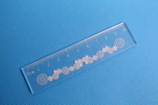
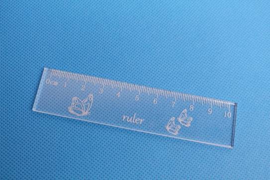
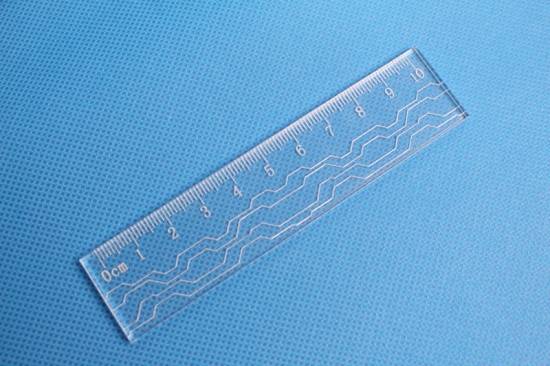
The following figure shows the various ruler works of the LaserBlock open source community for your reference and appreciation.
Among the works produced by laser cutting technology, there are planar works and three-dimensional works.
Models built with cut two-dimensional structures (building blocks) range from simple devices to highly crafted models, and the subtleties of their stacking and nesting are breathtaking. From the ground up, let’s start from the basic modeling methodology, from the two-dimensional modeling of points, lines and graphs, to the three-dimensional object modeling composed of points, lines and planes.


.png "laser cutter Globle")


