


Design for Metal 3D Printing: 8 Essential SLM Design Guidelines
 2026-10-16
WHAT ARE YOU LOOKING FOR?
Search Across Products, Blog Posts, Support Content, And Resources.

Design for Metal 3D Printing: 8 Essential SLM Design Guidelines
2026-10-16

Metal 3D printing makes it possible to manufacture complex internal channels, integrated components, lightweight structures, and functional prototypes that would be difficult to produce through conventional machining. But greater design freedom does not mean every CAD model is ready to print.
Selective laser melting (SLM), a form of laser powder bed fusion (LPBF), builds metal parts layer by layer using a laser and metal powder. Unlike CNC machining, where tool access is often a primary design constraint, SLM introduces a different set of considerations: build orientation, thermal behavior, supports, powder evacuation, and post-processing.
For engineers developing parts with complex geometries for metal 3D printing, understanding these requirements is essential to turning a promising design into a successful physical component.
This guide covers the fundamentals of Design for Additive Manufacturing (DfAM), eight essential SLM design guidelines, common design mistakes, and a practical workflow for moving from CAD to a functional metal prototype.
Whether you're preparing your first SLM project or improving an existing part, the goal is the same: design a component that can be printed, finished, inspected, and used—not merely a geometry that can be modeled.
Design for Additive Manufacturing (DfAM) is the practice of developing or adapting parts to make effective use of additive manufacturing while accounting for the capabilities and limitations of the chosen process.
Traditional Design for Manufacturing (DFM) focuses on whether a design can be produced efficiently through a specific manufacturing method.
For CNC machining, this often means considering cutting-tool access, workholding, toolpaths, material removal, and the number of setups.
For SLM, engineers must instead evaluate how the part will be built layer by layer, how heat will be managed, where support structures will connect, and what must happen after printing.
DfAM is therefore not simply about making a part lighter or more complex. It is about designing the entire manufacturing route.
Design around function, not the original manufacturing method.
An existing CNC assembly should not automatically be reproduced as a collection of identical printed parts. Engineers may have opportunities to consolidate components, modify internal features, or eliminate certain assembly constraints.
Balance geometric freedom with manufacturability.
A complex internal channel may be printable but difficult to clean. A thin structure may form successfully yet distort during separation from the build plate. A feature that looks excellent in CAD may require significant finishing before it becomes usable.
Consider the finished part from the beginning.
Material condition, dimensional tolerances, support removal, machining access, inspection, and repeatability should influence the original design rather than being left until after printing.
These principles form the foundation of the eight design checks below.
Build orientation determines how a component is positioned inside the SLM printer.
The same part can require very different supports, build times, and finishing operations depending on its orientation.
Consider a long metal bracket.
Positioning it vertically may reduce its footprint on the build plate, leaving space for other components. However, it can increase the number of printed layers and overall build time.
Placing it horizontally may reduce the build height but create large downward-facing regions that require support structures.
Neither arrangement is automatically better.
Choosing the orientation that fits the greatest number of parts on the platform without considering support removal, dimensional stability, or total manufacturing time.
Identify critical surfaces, likely support areas, internal passages, and functional load directions before selecting an orientation.
Compare multiple orientations, including their expected finishing requirements.
CAD review question: Is the selected orientation optimized for the complete manufacturing process rather than only for build-platform utilization?
SLM can produce thin walls, ribs, small holes, and fine structural details. However, a feature that can be printed under favorable conditions is not necessarily suitable for functional use.
A thin wall may be affected by thermal distortion, support-removal forces, powder cleaning, or handling after the build.
The important question is not simply, "What is the minimum printable wall thickness?"
It is, "What wall thickness will reliably satisfy the design's mechanical and manufacturing requirements?"
Wall thickness interacts with several other design variables:
For example, a short, well-connected wall and a tall, free-standing wall of identical thickness may behave very differently during printing.
Using a published minimum wall thickness from another material or printer as if it were a universal SLM design limit.
Identify critical walls, slender ribs, small pins, narrow gaps, and fine details in the CAD model.
For each feature, distinguish between what is geometrically printable and what is structurally acceptable.
Where possible, avoid unnecessary thin sections, improve support from surrounding geometry, and discuss critical limits with the manufacturing team.
CAD review question: Are the smallest features suitable for both printing and the mechanical demands of the finished part?
SLM builds each new layer on previously processed material or supported regions.
Downward-facing surfaces, large overhangs, and some other geometries may require support structures to maintain stability, manage heat, or reduce distortion.
Supports make certain designs manufacturable, but they also require material, printing time, removal work, and potentially additional finishing.
Geometry changes can sometimes reduce support requirements.
For example, a horizontal internal passage with a broad, flat ceiling may be more difficult to build without support than a channel with an appropriately designed arch or teardrop-like cross-section.
However, the actual result depends on channel size, orientation, material, and process parameters.
A commonly cited overhang angle should not be treated as a guarantee that a feature will print without support.
Designing complex internal cavities without checking whether necessary supports can be reached and removed afterward.
A part can finish printing successfully and still be unusable because supports remain trapped inside.
Review all downward-facing regions and potential support contact points.
Where supports are necessary, prefer accessible locations and avoid critical functional surfaces when practical.
If a support cannot be removed, evaluate whether the geometry or build orientation needs to change.
CAD review question: Can every required support be manufactured, accessed, and removed without damaging the component?
One of the most useful capabilities of metal 3D printing is the ability to create internal passages and geometries that are difficult or impossible to reach with conventional cutting tools.
This opens opportunities for compact manifolds, conformal cooling channels, airflow components, and integrated fluid-handling features.
But internal complexity introduces a significant practical challenge: unused powder must be removed from spaces intended to remain open.
During the build, loose powder surrounds the printed geometry and may remain inside internal passages.
A channel that is fully enclosed or has narrow, inaccessible openings can be difficult to clean.
Provide accessible openings. Design suitable entry, exit, or powder-removal paths wherever the intended function allows.
Avoid unnecessary dead ends. Blind cavities and convoluted passages may trap unused powder.
Consider channel length and curvature. Long passages, sharp turns, and branches can make powder evacuation and inspection more challenging.
Evaluate internal support requirements. An internal channel may be easier to print with a self-supporting profile than with a broad, flat ceiling.
Plan verification. For functional channels, manufacturers may need a method to confirm cleanliness, continuity, and dimensional acceptability.
Focusing on the complexity of the internal geometry while ignoring how powder will be removed or how the channel will be inspected.
Trace each passage through the CAD model.
Identify possible powder-trapping regions and consider how the part can be oriented or manipulated during cleaning.
Where required, incorporate openings that serve both cleaning and verification.
CAD review question: Can the internal structure be printed, cleared of unused powder, and verified before the part enters service?
Not every feature of a metal component needs to be printed to its final dimensions.
SLM offers strong geometric flexibility, but CNC machining may remain the more practical way to create certain precision features.
Examples include:
A metal part may benefit from SLM for its integrated internal geometry while relying on conventional machining for final precision.
If a feature will be machined after printing, engineers must account for the subsequent process while preparing the CAD model.
This can include appropriate machining allowance, accessible clamping surfaces, datum features, and tool access.
For more guidance on when to use each method, see our metal 3D printing vs. CNC machining comparison.
Designing a printed part with no accessible surfaces for secure workholding, then discovering that critical features cannot be machined accurately.
Mark critical dimensions and final surface requirements directly in the design review.
Decide which features should remain as-built and which require additional machining.
When an existing assembly contains several separately manufactured parts, also consider whether structural consolidation could simplify manufacturing without compromising inspection or maintenance. Thunder's cutting cone redesign case study offers a practical example.
CAD review question: Can precision-critical features be finished and inspected using a realistic post-processing setup?
SLM involves repeated local melting and solidification of metal powder.
The resulting heating and cooling cycles can generate thermal gradients, residual stresses, and dimensional distortion.
The severity depends on the material, part geometry, build orientation, supports, scan strategy, and subsequent processing.
Certain features may require additional attention:
These features are not automatically unsuitable for SLM, but they can introduce manufacturing challenges.
Assuming that if the digital geometry is dimensionally correct, the printed and separated component will have exactly the same shape.
Look for large differences in section thickness, potential heat concentration, and distortion-sensitive features.
Consider whether the geometry, supports, or build orientation should change.
For demanding applications, engineering teams may use simulation, validated process settings, stress-relief treatment, and dimensional inspection.
CAD review question: Has the design accounted for distortion risks during printing and after removal from the build platform?
A successful build does not automatically produce a finished functional component.
Depending on the application, SLM parts may require:
These steps should influence design decisions before printing begins.
Consider whether tools, fixtures, and inspection equipment can reach the surfaces that require additional work.
An external support connection may be easy to remove, while a similar connection deep inside a narrow cavity could be impractical.
Likewise, a critical mounting surface may be easy to machine only if the component can be held securely.
Inspection should reflect the intended application.
A basic fit-check prototype may only require dimensional and visual verification.
A functional component used under demanding loads may require additional material, geometric, or internal-quality inspection.
Some internal features may call for specialized non-destructive testing, depending on the risk and acceptance requirements.
Completing the CAD model without deciding how the part will be separated, supported during machining, cleaned, and inspected.
Create a simple finishing and inspection plan alongside the build preparation.
Identify the required finished surfaces, accessibility constraints, acceptance criteria, and any special inspection needs.
CAD review question: Can the component be converted from an as-built print into an accepted finished part using available processes?
SLM is well suited to evaluating complex functional prototypes, but a successful single print does not automatically establish a repeatable production process.
When moving from prototyping to small-batch manufacturing, additional factors become important.
Multiple parts may share the same printing job, but build efficiency depends on part orientation, height, support requirements, and the available build area.
Increasing the number of parts on the platform does not always improve total productivity if finishing and inspection become more difficult.
Repeated production may require controlled material handling, documented build preparation, stable process parameters, and appropriate quality checks.
If a design changes significantly, its previous manufacturing assumptions may need to be reviewed.
Optimizing a prototype only for a one-time successful print without considering whether the same design can be manufactured repeatedly and economically.
If future production is likely, discuss expected quantities, batch frequency, quality requirements, finishing capacity, and repeatability during the prototype stage.
CAD review question: Will this design remain practical when it needs to be printed, finished, and inspected repeatedly?
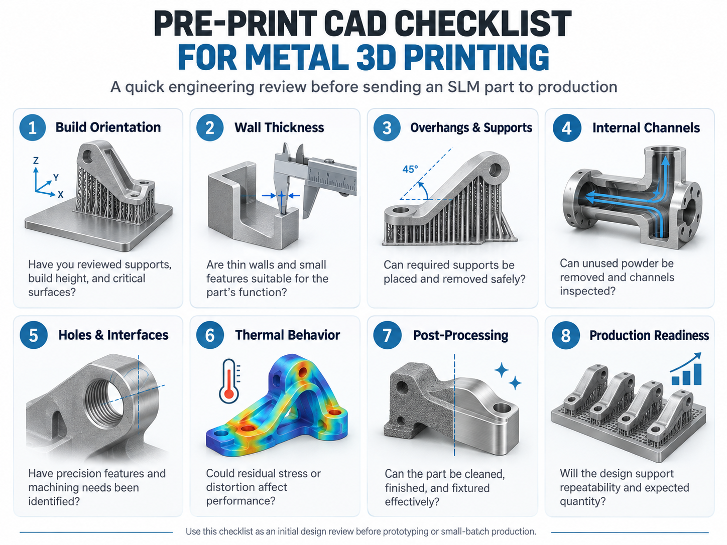
Many SLM design problems do not result from one incorrect dimension. They occur when an important manufacturing stage is overlooked.
Here are five common examples.
| Design Mistake | Why It Creates Problems | Better Approach |
|---|---|---|
| Selecting orientation only to fit more parts | May increase supports, distortion, or finishing requirements | Evaluate total build and finishing conditions |
| Designing sealed or inaccessible cavities | Unused powder may remain trapped inside | Plan accessible powder-removal paths |
| Using extremely thin features without functional review | Features may distort or become damaged | Review structural and process requirements together |
| Ignoring secondary machining | Critical surfaces may be difficult to finish accurately | Plan machining allowances, datums, and fixture access |
| Treating a successful first print as production-ready | Repeatability and quality acceptance may remain unverified | Establish manufacturing and inspection requirements |
The common theme is that a printable CAD model is only one step toward a successful metal component.
Once the basic design guidelines are understood, how should an engineering team approach a real metal 3D printing project?
A practical process can be organized into six stages.
Start with what the component must accomplish.
Document the intended application, functional loads, operating environment, material requirements, critical tolerances, surface finish expectations, and anticipated quantity.
Without clear requirements, it is difficult to determine whether a printed prototype is successful.
Check the model for thin walls, unsupported regions, inaccessible cavities, complicated internal channels, and critical interfaces.
Also review the model's overall integrity, including unintended gaps, intersecting bodies, and other geometry issues that could interfere with manufacturing preparation.
Choose a material supported by the available machine and established process.
Review potential build orientations, support requirements, build height, and the placement of critical surfaces.
If multiple parts are involved, consider whether they can share a build without compromising quality or post-processing access.
Decide how the part will be supported during printing and removed afterward.
Identify areas that may need machining, heat treatment, or other finishing operations.
Define how critical dimensions and functional features will be inspected.
Prepare the build using an appropriate machine configuration and validated process settings.
After printing, complete the required removal, cleaning, finishing, and inspection operations.
Compare the manufactured prototype with the original functional requirements.
Identify issues related to geometry, dimensional accuracy, material behavior, or assembly.
Use those findings to determine whether the CAD design, build strategy, or post-processing plan needs another iteration.
This workflow helps connect the flexibility of digital design with the realities of physical manufacturing.
Before submitting a model for SLM production, use the following checklist for an initial engineering review.
| Design Check | Key Question |
|---|---|
| Functional requirements | Are the intended loads, material, tolerances, and usage conditions clear? |
| Build orientation | Have support requirements, height, surface quality, and distortion been considered? |
| Wall thickness | Are thin walls and small features suitable for the material and intended function? |
| Overhangs and supports | Can all necessary supports be placed and removed? |
| Internal passages | Can unused powder be removed and important channels verified? |
| Holes and interfaces | Have precision features and machining requirements been identified? |
| Thermal behavior | Have likely stress and distortion risks been reviewed? |
| Post-processing | Can the part be separated, cleaned, finished, and securely fixtured? |
| Inspection | Can all critical features be measured or otherwise verified? |
| Production plans | Can the design support the required quantity and repeatability? |
A design does not necessarily need to satisfy every item without modification before it is submitted for review.
Instead, use the checklist to identify uncertainties and discuss them with the manufacturing team.
Addressing these issues before printing can reduce unnecessary iterations and improve the likelihood of obtaining a usable functional prototype.
Good metal 3D printing design goes beyond creating shapes that are difficult to machine.
It requires engineers to connect part geometry with build orientation, material behavior, supports, powder removal, finishing, inspection, and future production requirements.
Understanding these factors makes it easier to use SLM where it delivers real value—particularly for complex functional prototypes, integrated components, and selected small-batch applications.
For teams new to metal additive manufacturing, the most effective starting point is not necessarily a more complicated design.
It is a clearer understanding of what the final part must achieve and how the entire manufacturing process can deliver that result.
The goal is not simply to create a printable CAD model. It is to develop a metal component that can be manufactured reliably, finished efficiently, and validated for its intended application.
Preparing a complex metal prototype or evaluating a part for additive manufacturing?
Explore Thunder SLM metal 3D printing solutions and discuss your CAD model, material selection, tolerances, and manufacturing requirements with our technical team.
Talk To Our Experts Now!
Please leave your contact information so that we can serve you better.
FIND THE RIGHT LASER FOR YOUR NEXT PROJECT
Explore Thunder Laser solutions designed for different materials, workflows, and production needs.


 Stable & Consistent MachinesUnlimited ApplicationsRobust After-sales SupportFactory Direct Supply


