


Beyond Traditional Machining: How Metal 3D Printing Enables Complex Geometries
 2026-10-13
WHAT ARE YOU LOOKING FOR?
Search Across Products, Blog Posts, Support Content, And Resources.

Beyond Traditional Machining: How Metal 3D Printing Enables Complex Geometries
2026-10-13

A metal part may look simple from the outside while hiding its most important features inside: a curved passage, a lightweight cellular core, or an integrated flow network. These features can be difficult to machine—not because CNC machining lacks precision, but because cutting tools need physical access.
Metal 3D printing changes that design constraint. With laser powder bed fusion (LPBF), a component is built layer by layer from metal powder, making certain internal and interconnected geometries possible without the same tool-access requirements. The more useful question, however, is not “Can it be printed?” It is “Does printing this geometry improve the complete manufacturing outcome?”
CNC machining remains an excellent choice for precision surfaces, accessible features, and many production parts. Challenges arise when a design needs curved enclosed channels, interlocking internal spaces, or features that cannot be reached with a cutting tool.
A curved passage might require intersecting drilled holes and plugs; an enclosed cavity might require two machined halves and a sealed joint. Neither method is inherently wrong. The engineering question is whether redesigning the geometry can eliminate a difficult operation or critical interface without introducing a worse problem downstream.
LPBF offers another path: redesign the component around its required function rather than around cutting-tool access. This approach is closely related to design for additive manufacturing (DfAM).
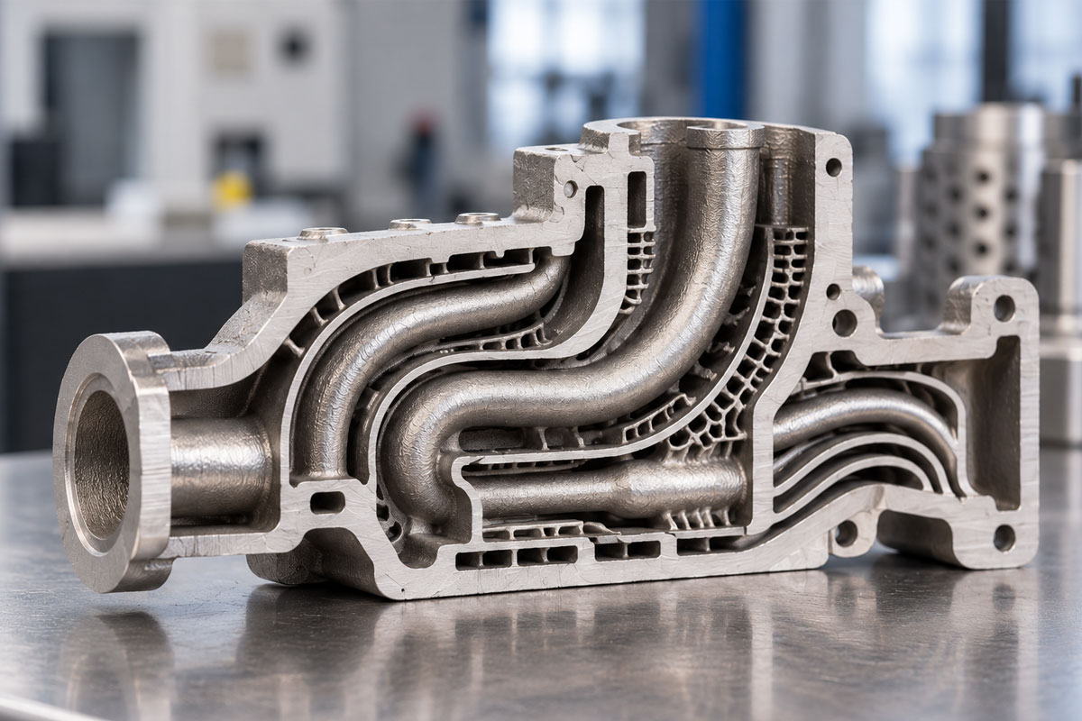
Internal passages can be routed along three-dimensional paths, making LPBF useful for selected thermal-management components, fluid manifolds, and tooling concepts such as conformal cooling in mold making. The benefit comes from where the passage can be positioned—not from complexity for its own sake.
Channels still need an achievable shape and size, a practical path for removing loose powder, and an inspection strategy. An enclosed channel that cannot be cleared or verified may not be a viable production design.
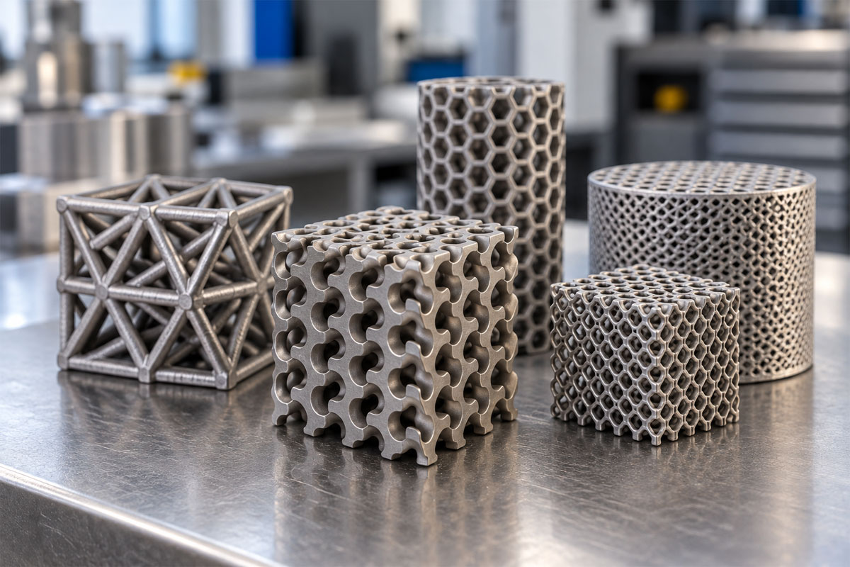
A lattice is worth considering when engineers need to distribute material differently—not merely to create a striking pattern. Its potential value may be lower mass or tailored stiffness, but only where loading and validation support the design.
The geometry must be evaluated against actual loads and manufacturing constraints. Thin features, trapped powder, surface condition, and inspection can be as important as the lattice pattern itself.
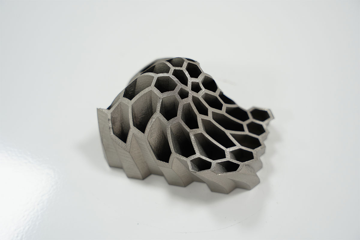
A hollow region can reduce mass or accommodate an internal function, yet it may also trap unmelted powder. The design decision is therefore not just whether to hollow the part, but whether the remaining wall, access openings, and inspection plan make that cavity useful.
That freedom brings responsibilities: provide powder-evacuation routes, avoid inaccessible supports, and assess whether critical internal surfaces need secondary finishing.
Manufacturing access can force engineers to split a functional design into several machinable pieces. LPBF can sometimes bring those features back into fewer parts, potentially reducing joints and handling—but not necessarily total production work.
Part consolidation only creates value if the full process improves. Build time, powder handling, heat treatment, support removal, machining, inspection, and remaining assembly operations all belong in that assessment.
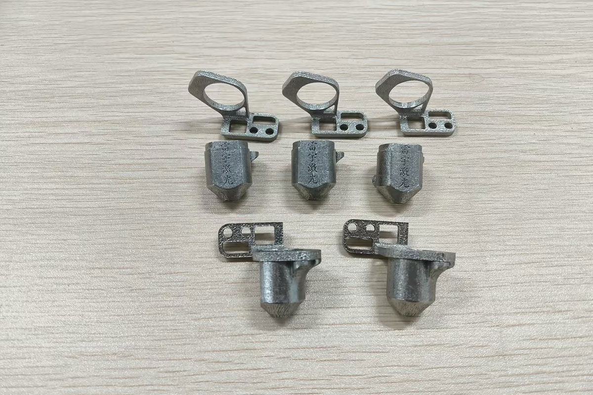
Thunder Laser's internal SLM application materials document a metal cutting-system cone that was redesigned from a conventionally machined, three-piece arrangement to a two-part configuration for additive manufacturing.
This is an example of how a new manufacturing process can prompt a different component architecture. It does not mean that printing is inherently faster or less expensive for every component. Any production-time or cost comparison should use verified, like-for-like assumptions, including batch size and post-processing.
Thunder's SLM materials also show complex hollow and lattice demonstration structures. Together, these samples provide a stronger illustration of design freedom than generic illustrations alone: they connect the concept to geometries the Thunder team has actually explored.
A practical go/no-go test: Before committing to a build, identify the hardest-to-access internal feature, show how powder will leave it, specify which surfaces need machining, and name the inspection method. If any of those steps is unresolved, the design is not production-ready just because it looks printable in CAD.
These checks are especially important when moving from a visually impressive prototype to a working industrial component.
Start with the bottleneck. Is it tool access, assembly complexity, customization, or tooling lead time? SLM is most worth evaluating when one of these constraints is material to the project and the planned geometry can still be cleaned, finished, and inspected.
It may be less attractive for a straightforward geometry that can be machined quickly and economically at the required volume. Many successful workflows combine additive manufacturing with conventional finishing rather than treating them as alternatives.
Before selecting a process, review the alloy, required build envelope, critical dimensions, production quantity, powder-removal access, post-processing, inspection requirements, and acceptable total cost. For a deeper evaluation of equipment and production fit, see our SLM metal 3D printer buyer’s guide.
LPBF expands what engineers can design, but its strongest value appears when geometry is matched to a measurable manufacturing need. Curved channels, lattices, hollow regions, and consolidated assemblies should improve function, workflow, or the economics of an application—not simply demonstrate that a machine can print a complicated shape.
Thunder Laser's SLM series supports qualified metal additive manufacturing workflows, from engineering exploration to selected functional prototypes and small-batch parts. Feasibility depends on the part, alloy, process settings, material selection, and validation requirements.
For a broader introduction to SLM use cases and the manufacturing considerations involved in mold and tooling projects, read our SLM Metal 3D Printers: The 2026 Ultimate Guide. This article focuses specifically on evaluating complex geometry for manufacturability.
Explore Thunder SLM metal 3D printing solutions and share your part requirements with our technical team for an application assessment.
Yes. LPBF can create certain three-dimensional internal passages that are difficult to access with traditional cutting tools. Powder evacuation, feature geometry, and inspection must be planned from the design stage.
They can distribute material differently within a part, potentially enabling lightweighting or tailored mechanical behavior. The benefits depend on design, loading, material, process quality, and validation.
Not universally. SLM is attractive for selected complex and customized parts, while CNC often remains efficient for accessible precision features and many production volumes. Hybrid workflows are common.
No. Supports, thermal effects, minimum features, trapped powder, finishing, and inspection can prevent a digital design from becoming a usable part.
Talk To Our Experts Now!
Please leave your contact information so that we can serve you better.
FIND THE RIGHT LASER FOR YOUR NEXT PROJECT
Explore Thunder Laser solutions designed for different materials, workflows, and production needs.


 Stable & Consistent MachinesUnlimited ApplicationsRobust After-sales SupportFactory Direct Supply


