


Remote-Control Souvenir Medal Dispenser Laser Cutting Project with LaserMaker
 24-07-25
WHAT ARE YOU LOOKING FOR?
Search Across Products, Blog Posts, Support Content, And Resources.

Remote-Control Souvenir Medal Dispenser Laser Cutting Project with LaserMaker
24-07-25

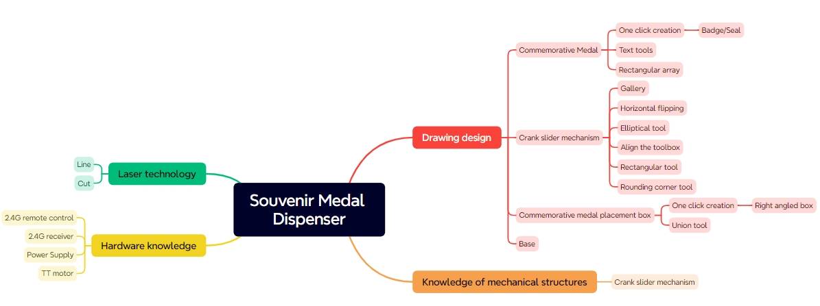
In this STEAM robotics and mechanism project, students design and build a remote-control souvenir medal dispenser using LaserMaker. The lesson connects badge design, laser-cut medal holders, a crank-slider mechanism, TT motor control, receiver wiring, structural assembly, and hands-on testing.
This project helps students understand how a rotating motor can push medals out one by one. Students design the medals, build a crank-slider mechanism, create a medal holder with an entry and exit slot, and assemble everything on a stable base.
| Item | Details |
|---|---|
| Project | Remote-control souvenir medal dispenser |
| Software | LaserMaker |
| Main Skills | Badge/Stamp tool, Rectangle Tool, Ellipse Tool, Text Tool, Rectangular Array, Rounded Corner Tool, Union, alignment, horizontal flip, box creation, outlining, cutting, wiring, and assembly |
| Suggested Material | Basswood plywood, 40 cm × 60 cm × 3 mm |
| Classroom Fit | Robotics and mechanism projects, crank-slider mechanisms, automated dispensing, maker education, laser cutting, and remote-control structures |
Students will design a working souvenir medal dispenser that can store a stack of medals and push them out through an exit slot. They will create laser-cut medals, design a crank-slider mechanism, build a medal holder and base, connect the remote-control circuit, and test the dispensing action.
For teachers: Use this project to connect rotation, translation, linkage mechanisms, automated product dispensing, laser-cut structure design, and iterative testing.
For students: Use the activity to design a functional dispenser while learning how a motor-driven crank-slider mechanism creates push-out motion.
For makerspaces: Use it as an advanced classroom mechanism project that combines laser cutting, badge design, electronics, and mechanical assembly.
Design round souvenir medals with the Badge/Stamp tool and prepare them for outlining and cutting.
Use a disc, connecting rod, slider, and groove to create a crank-slider mechanism.
Design a medal holder with a slider entry, medal exit, fixation holes, and open-top storage structure.
Create a base plate and brackets for supporting the motor, receiver, battery, medal holder, and mechanism.
Assemble the mechanical system, connect the circuit, and test whether medals can be dispensed smoothly.
Design thinking: Turn a visitor-service idea into a functional automated dispenser with a clear medal path and stable structure.
Computational thinking: Use diameter, stroke, hole spacing, arrays, alignment, part clearances, and box dimensions to create accurate laser-cut parts.
Engineering thinking: Consider slider travel, medal diameter, friction, motor speed, groove clearance, fastener placement, base stability, and reliable dispensing.
Students should test powered mechanisms carefully under teacher or lab supervisor guidance. Keep fingers, loose wires, and small parts away from the rotating disc, connecting rod, slider, and dispensing slot during operation.
Souvenir medals are often used in amusement parks, museums, school events, and visitor centers. Handing out medals one by one can be slow, especially when many visitors arrive at the same time. An automatic dispenser can make the process more engaging and efficient.
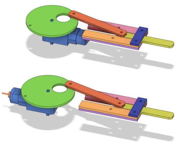
In this project, students explore how a crank-slider mechanism converts the circular motion of a TT motor into linear motion. The slider pushes one medal out of the holder, retracts, and allows the next medal to drop into position.

Before modeling the medal dispenser, students should identify the remote-control components, structural material, fasteners, and small accessories used in the project.
| No. | Name | Quantity |
|---|---|---|
| 1 | 2.4G Remote Control with battery | 1 |
| 2 | 2.4G Receiver | 1 |
| 3 | TT Motor, 1:220 gear ratio | 1 |
| 4 | 18650 Battery with wire | 2 |
| 5 | Basswood Plywood, 40 cm × 60 cm × 3 mm | 1 |
| 6 | M3 flat head screws, M3 nuts, and M3 × 6 single-pass copper standoffs | Several |
| 7 | R3080 nylon rivets | 2 |
| 8 | Cable ties | 2 |

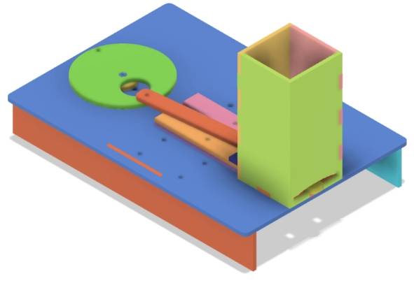
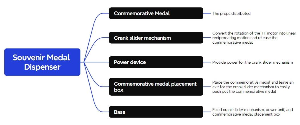
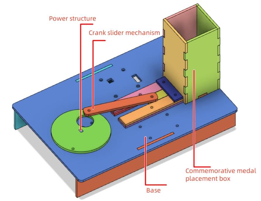
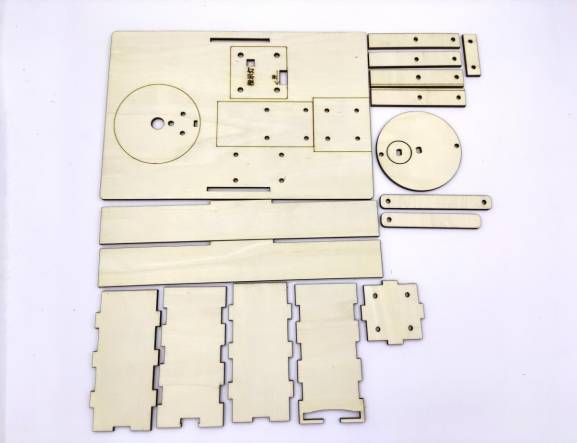
The laser-cut structure is organized into five main part groups: souvenir medals, crank-slider mechanism, power unit, medal holder, and base.
| Part No. | Part Name | Quantity | Function |
|---|---|---|---|
| 1 | Souvenir Medal | 10 | Item to be dispensed |
| 2 | Crank-Slider Mechanism | 1 | Pushes out the souvenir medals |
| 3 | Power Unit | 1 | Provides power to the crank-slider mechanism |
| 4 | Medal Holder | 1 | Stores the souvenir medals |
| 5 | Base | 1 | Secures and stabilizes the components |
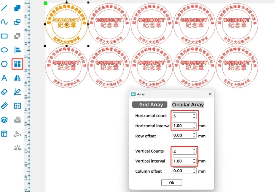
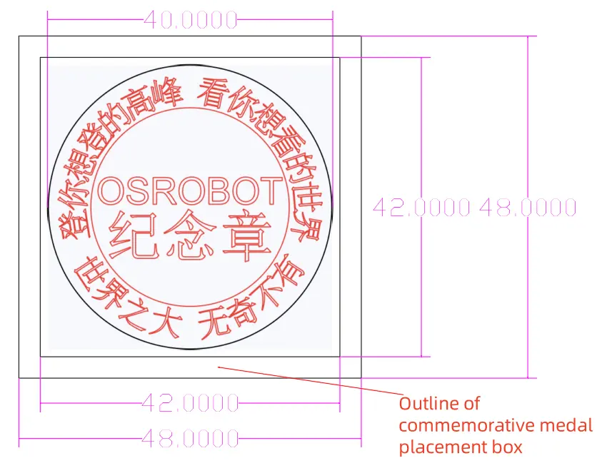
Common souvenir medals are round, so this lesson begins with a circular medal design. Open LaserMaker, choose Creation, then select Badge/Stamp. In the source workflow, the initial badge uses a 60 mm outer diameter and 42 mm inner diameter before being scaled down.
Add circular text around the medal and center text in the middle. The source workflow uses sample text such as “Souvenir Medal” and “OSROBOT.” After the badge is generated, resize the complete medal design to 40 mm by 40 mm.
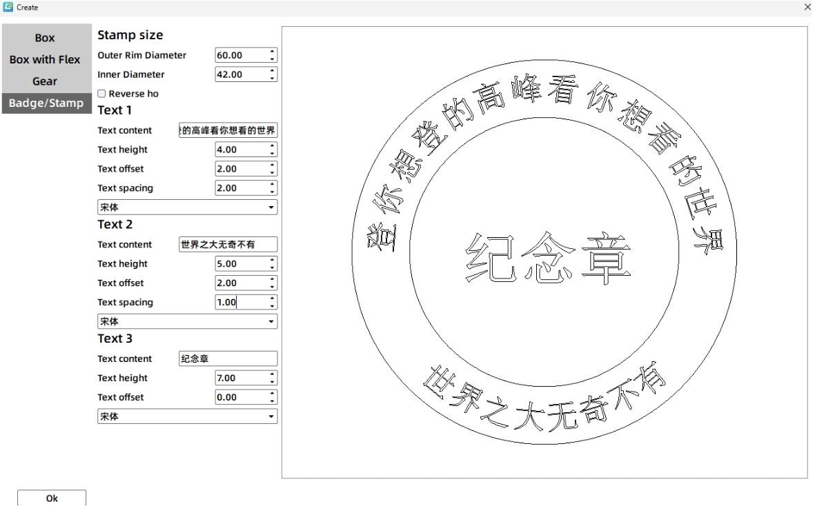

Set the outer medal circle to the black cutting layer so the medal is cut out. Set the inner graphics and text to the red outlining layer so they are marked on the surface without cutting through. Then use Rectangular Array to create 10 medals, arranged as 5 horizontally and 2 vertically with 1 mm spacing.
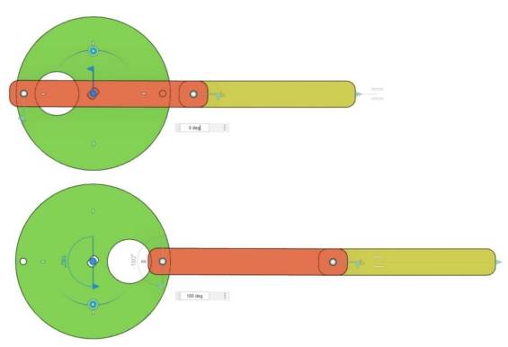
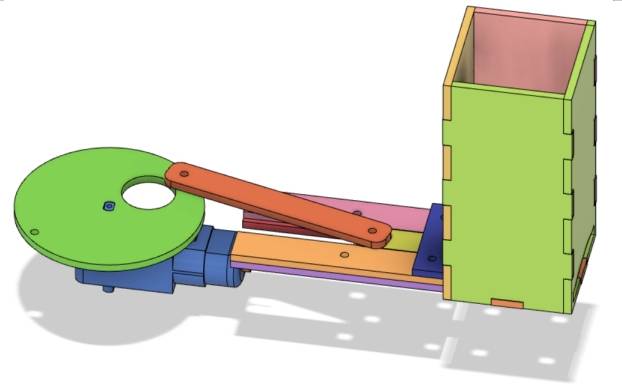
The crank-slider mechanism is powered by a TT motor. The motor drives the disc, the disc drives the connecting rod, and the connecting rod pushes the slider back and forth.
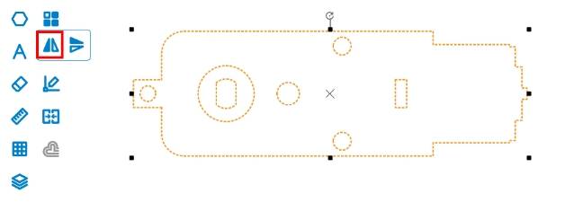
Select the TT Motor graphic from the Open-Source Robot library and drag it onto the canvas. In the source workflow, the motor shaft needs to face left to save space, so the motor graphic is flipped horizontally and grouped before further design work.
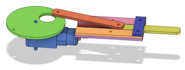
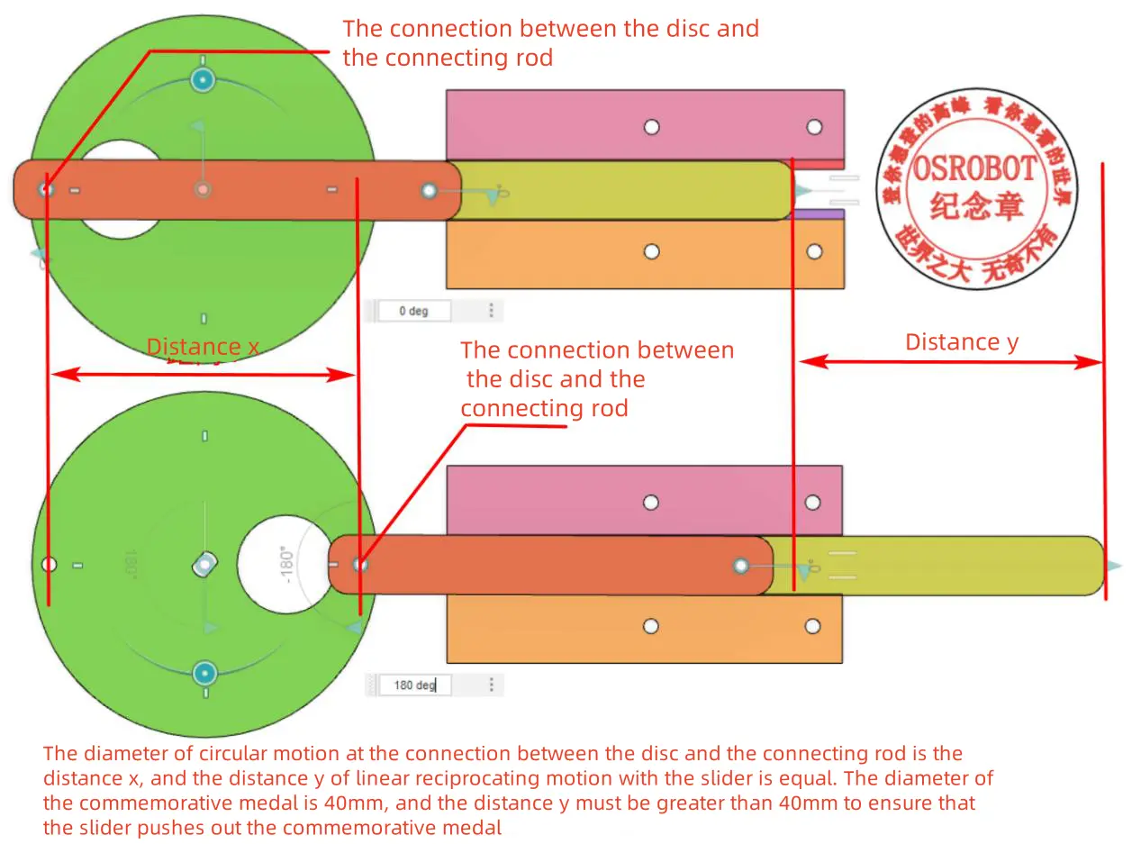
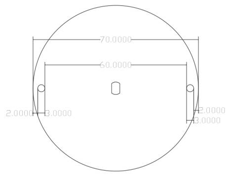
The source workflow uses a disc instead of a long crank to make the mechanism run more smoothly. Because each medal is 40 mm in diameter, the motion diameter at the connecting point should be greater than 40 mm. The source workflow sets the disc diameter to 70 mm.
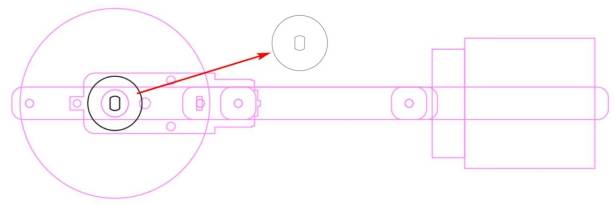
Draw a 70 mm circle for the disc. Draw a 10 mm circle as a positioning reference, center-align it with the disc, and use it to align the disc center with the TT motor shaft position.
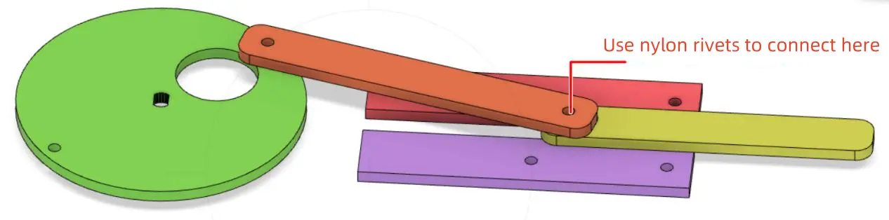
The disc connects to the connecting rod with an R3080 nylon rivet, so the disc needs 3 mm connection holes near the edge. In the source workflow, two 3 mm holes are drawn with 60 mm spacing between the inner walls, then aligned to the center of the disc.
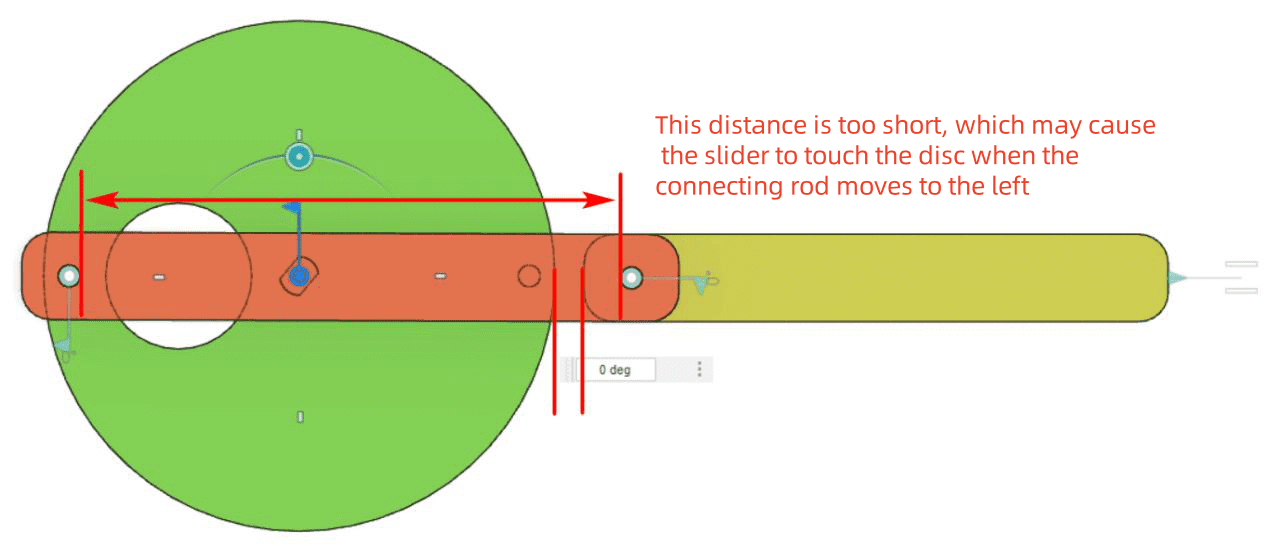
The connecting rod links the disc and slider. To prevent the slider from colliding with the disc, the source workflow sets the connecting rod hole spacing to 74 mm, which is greater than the disc diameter.
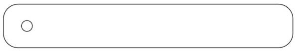
Draw two 3 mm holes with 74 mm spacing. Then draw a 90 mm by 12 mm rounded rectangle with a 4 mm corner radius. Center-align the holes inside the rounded rectangle and group the rod.
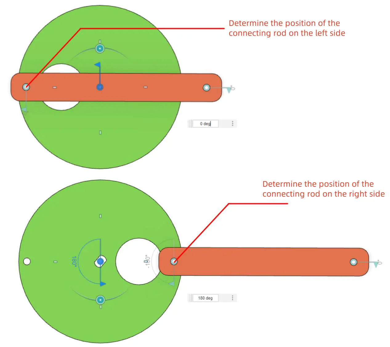
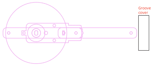
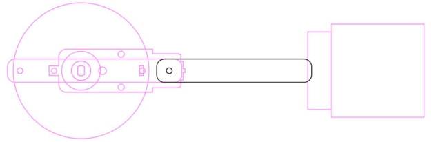
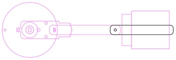
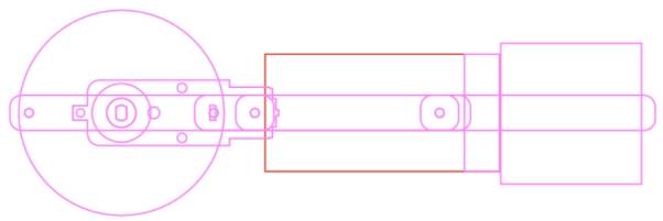
To understand the stroke, align the left hole of the connecting rod with the leftmost and rightmost holes on the disc. These two positions show the movement limits of the slider and help determine the next parts.
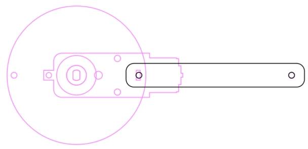
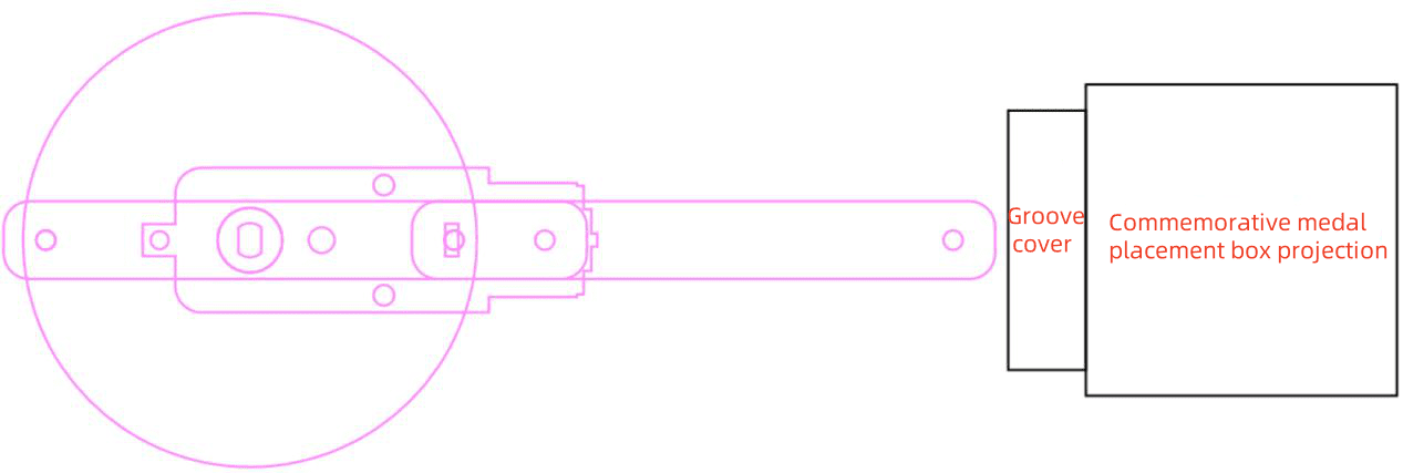
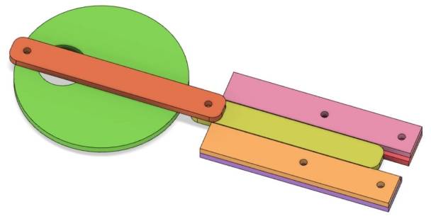
The groove restricts the slider’s path, and the recess cover helps prevent the slider from leaving the groove. The medal holder is placed to the right of the recess cover so the slider can push a medal out of the holder.
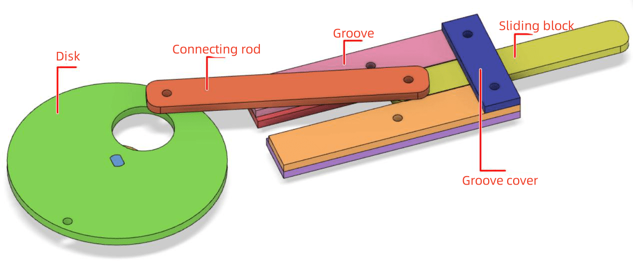
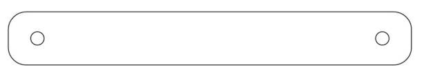
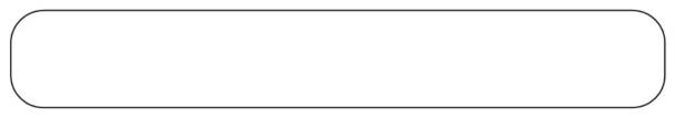
The slider performs the linear pushing action. Draw an 80 mm by 12 mm rounded rectangle with a 4 mm corner radius. Draw a 3 mm hole for connecting the slider to the connecting rod, align it to the left side, then move the hole 5 mm to the right.
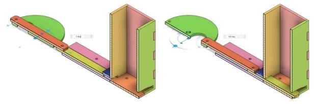
Test the slider position in both motion extremes. When the slider is at the leftmost position, its right end should remain under the recess cover. When it is at the rightmost position, its right end should extend beyond the medal holder enough to push a medal out.
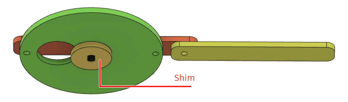
The TT motor is fixed with screws, and the screw heads may interfere with disc rotation. The source workflow adds a gasket under the disc to create clearance and reduce rubbing from the nylon rivet.
Draw a 20 mm circle, align it with the disc center, and use the TT hole position to make the gasket.
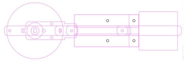
The groove limits the slider’s path. The source workflow uses three layers of basswood for the groove and cover structure. Draw reference shapes, create the first groove layer for rivet clearance, and create the second groove layer to keep the slider moving in a straight line.
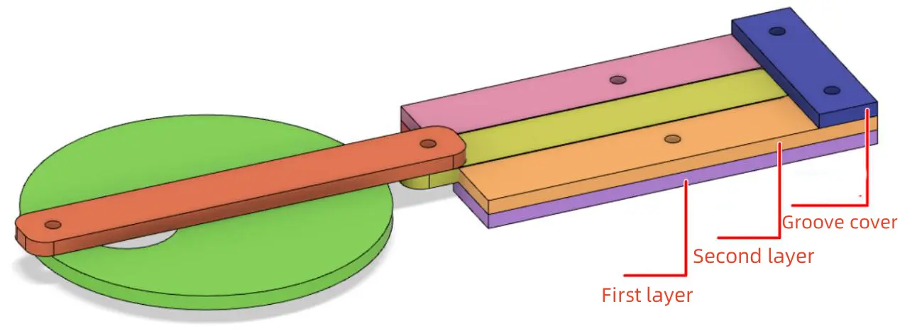
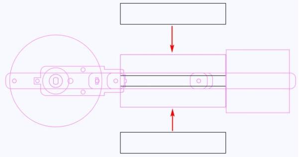
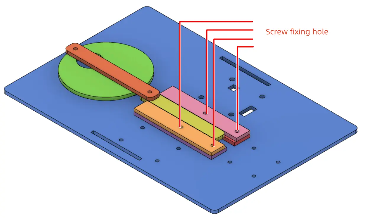
Add 3 mm screw holes to the groove and cover so they can be fixed to the base plate. Place the screw holes as far to the right as practical to reduce interference with the moving connecting rod.
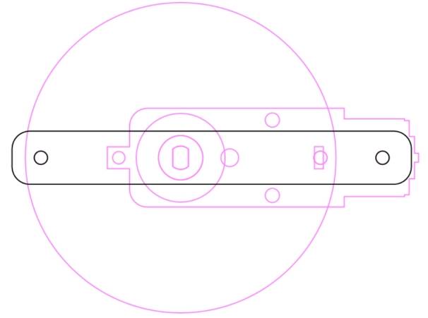
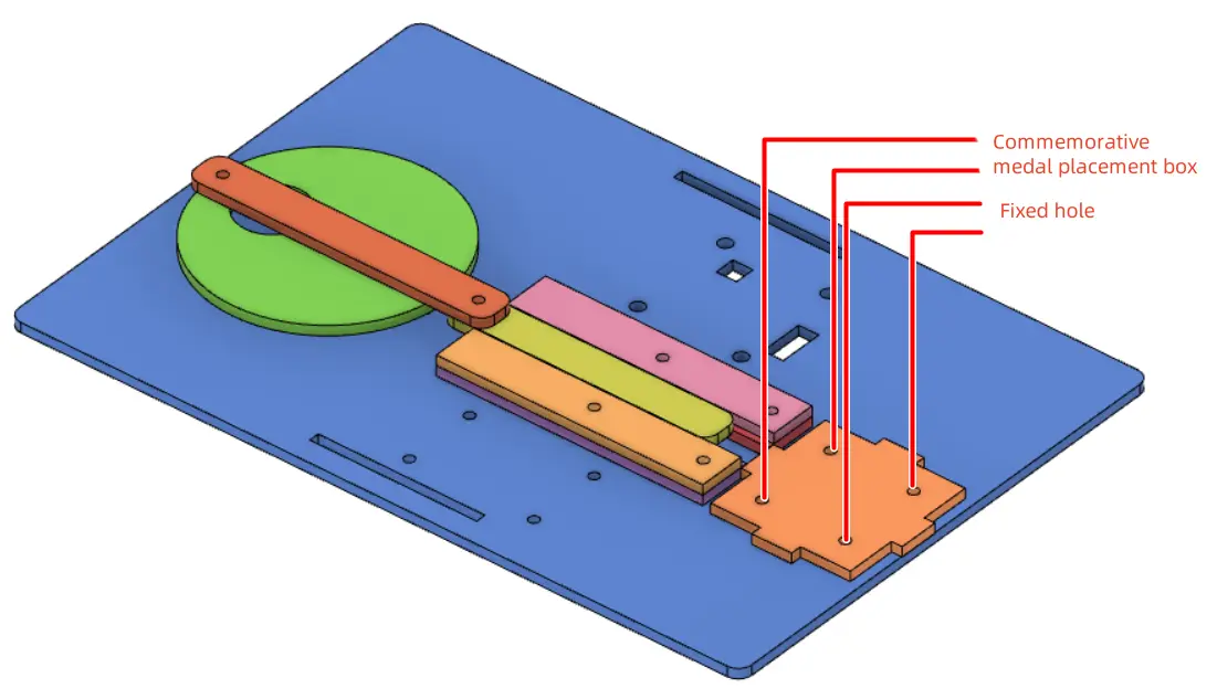
The medal holder stores the medals vertically. Based on the mechanism layout, the source workflow uses a 48 mm by 48 mm bottom projection and creates a 48 mm by 48 mm by 100 mm rectangular box with no top cover. The groove size is 12 mm, the material thickness is 3 mm, and the laser compensation is 0.1 mm.
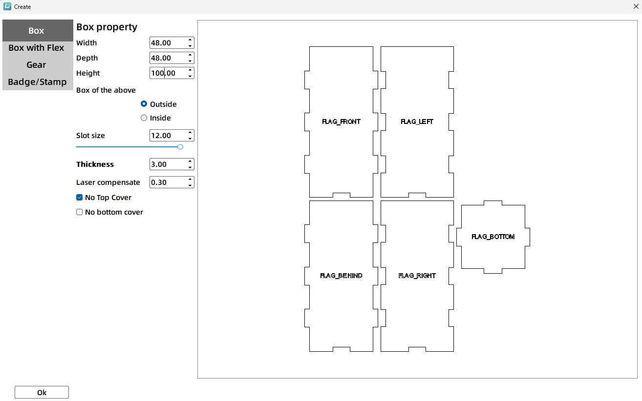
The slider enters the medal holder from one side, pushes the bottom medal out, then retracts so the next medal can fall into position. The slider entry should be slightly larger than the slider. In the source workflow, the entry is 13 mm wide and 3.2 mm high.
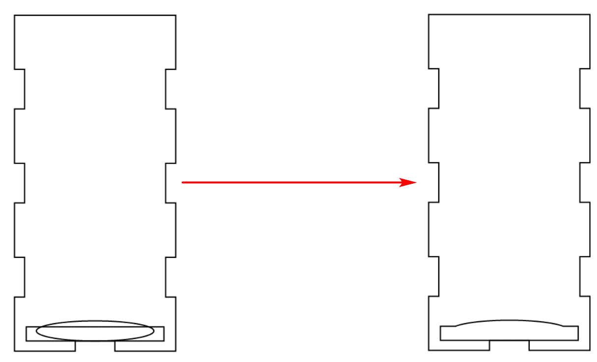
The medal exit should be slightly larger than the 40 mm medal. The source workflow combines a 41 mm by 4.2 mm rectangle with a 30 mm by 5 mm ellipse to create an exit shape with a curved lower section, helping the medal fall out more easily.
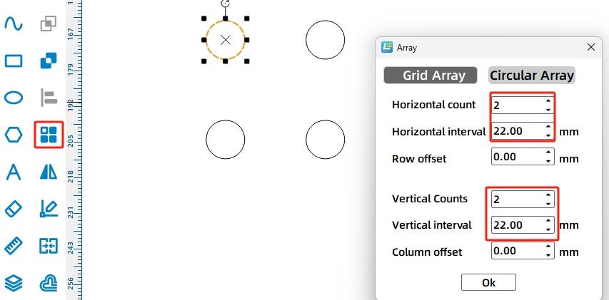
The medal holder is fixed to the base plate with screws and nuts. Draw four 3 mm holes using Rectangular Array, with 2 horizontal copies, 22 mm horizontal spacing, 2 vertical copies, and 22 mm vertical spacing.
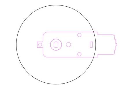
Use a 40 mm circle as a medal reference to check whether the screws will interfere with the medals. In the source workflow, the screw positions do not block the medal path.
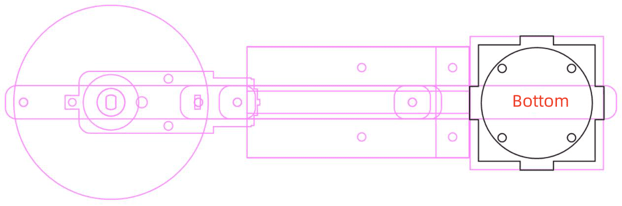
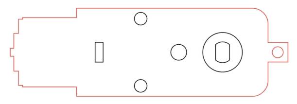
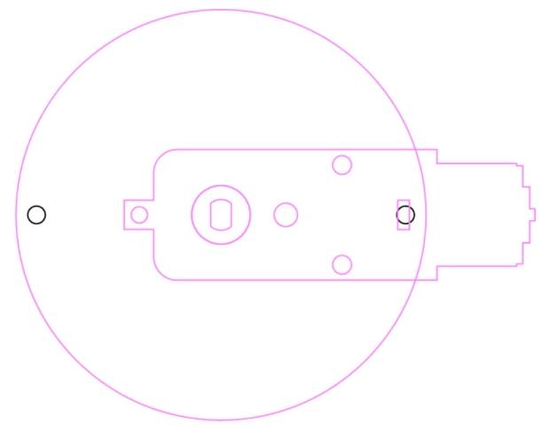
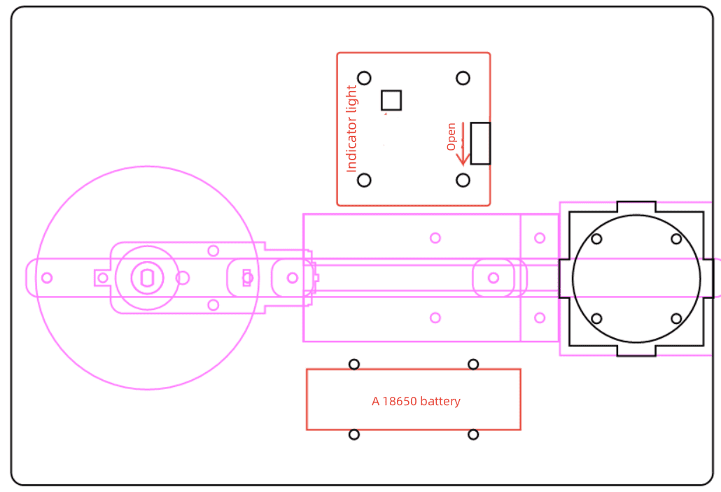
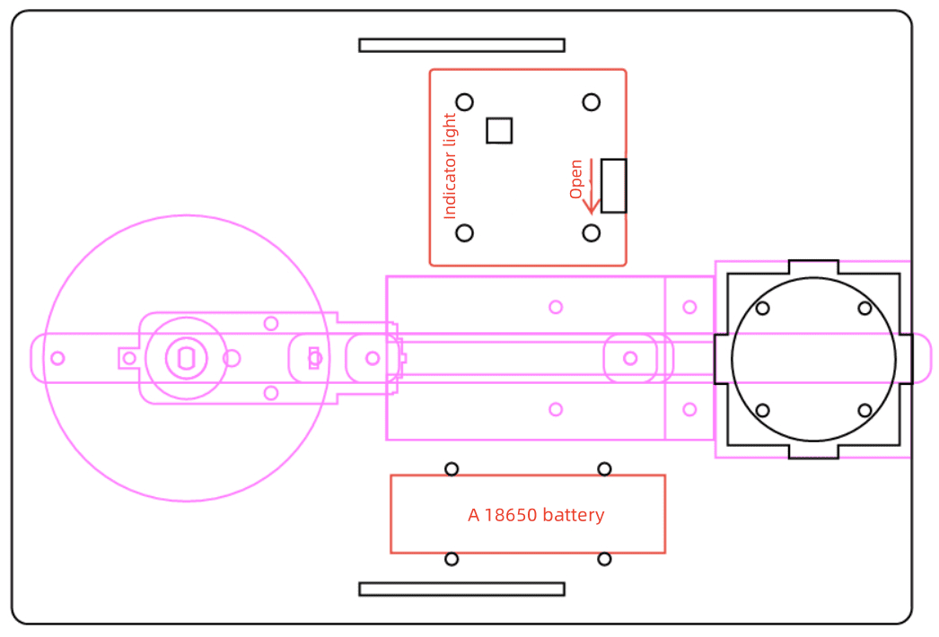
The base plate secures the crank-slider mechanism, medal holder, OSROBOT receiver, battery, and TT motor. In the source workflow, the base plate is 220 mm wide and 150 mm high with a 4 mm rounded corner radius.
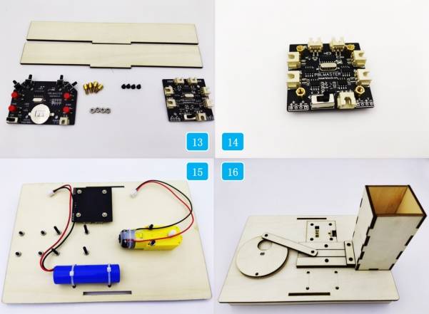
Add the OSROBOT2 control board graphic and 18650 battery strap fixation graphic from the Open Source Robotics section. Place the components in suitable positions, then adjust the base size and layout so the moving mechanism has enough space.
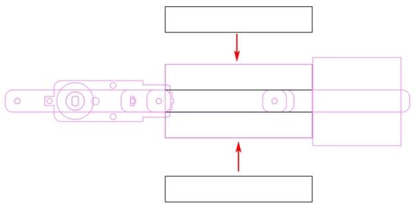
Because the TT motor, receiver board, and batteries are fixed below the base plate, the source workflow uses a double-bracket support structure. Draw two 50 mm by 3 mm mortises on the base plate with 130 mm vertical spacing.
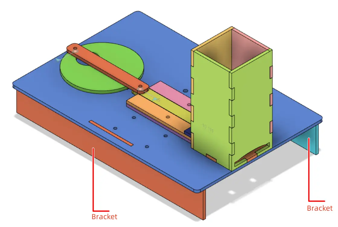
For each bracket, draw a 220 mm by 30 mm rectangle and add a 50.5 mm by 3 mm tenon. The extra 0.5 mm helps account for laser compensation in the source workflow. Align the tenon with the bracket, use Union to merge the shapes, then duplicate the bracket.

After the medal, crank-slider mechanism, groove, medal holder, base plate, and brackets are complete, arrange the parts for laser cutting. Ungroup any grouped design sketches if needed, copy the final production parts, assign the correct layers, and prepare the final layout.
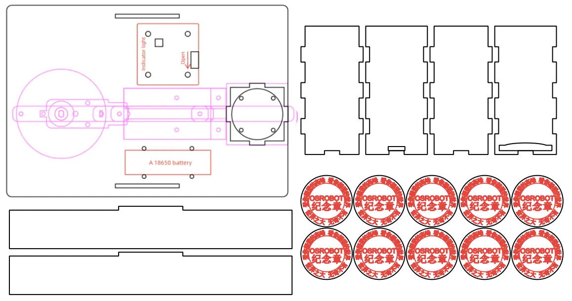
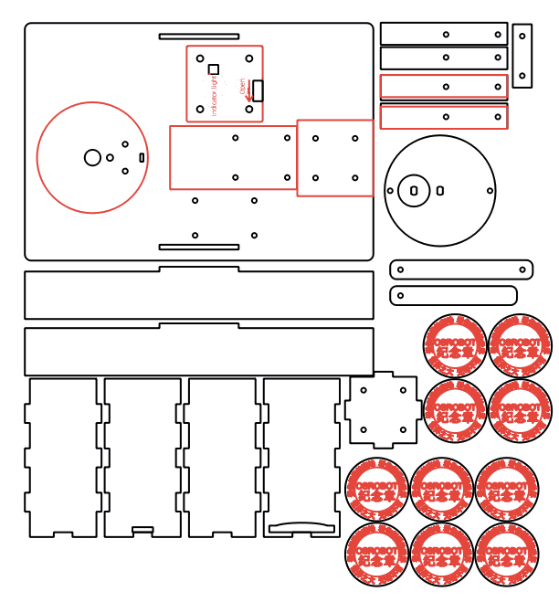
The medal dispenser project uses two main laser processes. Red-layer objects are used for outlining or surface marking, while black-layer objects are cut through the basswood plywood.
Outlining: Double-click the red block in the processing area. Select Basswood Plywood as the material, choose Outlining, and set the cutting depth to 0.10 mm.
Cutting: Double-click the black block in the processing area. Select Basswood Plywood as the material, choose Cutting, and set the cutting depth to 3.00 mm.
Turn on the laser cutting machine and laser switch. When the Start Fabrication button becomes ready, upload the drawing to the laser cutting machine and start cutting from the machine panel.
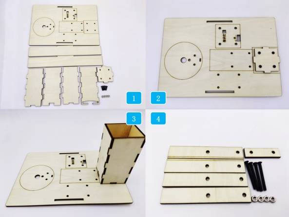
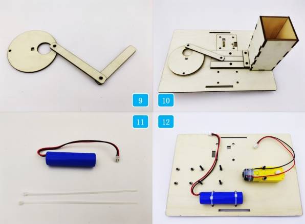
After laser processing, identify all cut parts before assembly. Keep the small rivets, screws, nuts, spacers, and brackets organized so students can assemble the mechanism in the correct order.
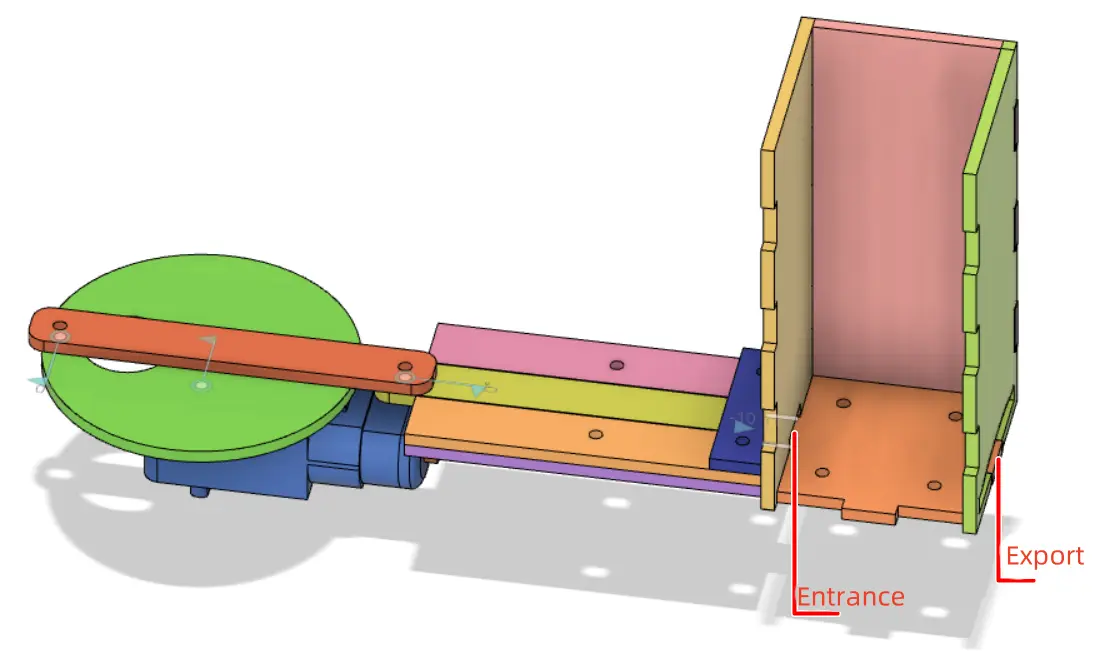
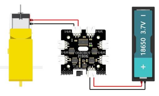
To activate the dispenser, connect the circuit according to the wiring diagram. The TT motor, battery, receiver, and remote-control components work together to drive the crank-slider mechanism.
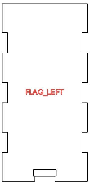
First, locate the base plate and medal holder box parts. Secure the bottom of the medal holder box to the base plate with screws and nuts, then assemble the front, back, left, and right sides of the holder.
Next, locate the groove-related parts and fix them to the base plate. These parts guide the slider and help keep the motion path straight.
Locate the TT motor and crank-slider mechanism components. Fix the TT motor to the base plate with screws and nuts, then install the spacer onto the TT motor shaft.
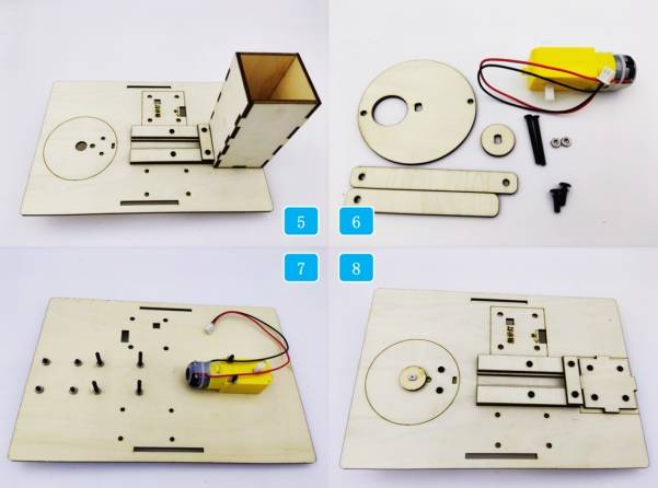
Assemble the connecting rod and slider to the disc using R3080 nylon rivets. Install the crank-slider mechanism onto the TT motor and groove so the slider can move along the guided path.
Secure the battery to the base plate with cable ties. Then install the OSROBOT2 control board using copper standoffs, screws, and nuts. Finally, install the base brackets to lift and stabilize the structure.
After assembly, turn on the control panel, switch the remote to battery mode, pair the remote-control system, and test whether the dispenser can push medals out through the exit slot.
Check whether the disc rotates smoothly without scraping the base plate or groove parts.
Test whether the connecting rod and slider move freely through the full stroke.
Confirm that the medal holder exit is large enough for medals to leave without getting stuck.
Review whether screws, nuts, rivets, and cable ties are secure before running the model.
Observe whether the last medal dispenses reliably, because the source lesson notes that the last medal may be more likely to jam.
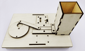
After design, laser processing, wiring, and assembly, students complete a remote-control souvenir medal dispenser. The project gives students practical experience with badge design, mechanical linkage, slider movement, box structures, laser-cut mechanisms, and automated dispensing.
The source lesson notes that the last medal may sometimes get stuck during dispensing. As an extension challenge, students can redesign the medal holder, adjust the exit shape, add a guide ramp, change the slider end shape, or test a spring-assisted follower to improve reliability.
Students can also improve the appearance of the dispenser by adding a themed front panel, clearer signage, decorative surface outlining, or a transparent viewing window while keeping the medal path and moving mechanism functional.
This project is suitable for classroom laser cutters that support cutting and outlining of sheet materials for small robotics and mechanism projects. For schools, makerspaces, and beginner STEAM labs, projects like souvenir medal dispensers, crank-slider models, automated pushers, and remote-control classroom mechanisms can be completed with a classroom laser cutter such as the Thunder Laser Bolt Series.
Teachers can choose the machine and material setup based on classroom space, material thickness, electronic components, moving-part clearance, and learning goals. The same LaserMaker workflow can also be adapted for other CO2 laser machines when students move on to larger automated dispensers or more advanced mechanism projects.
Talk To Our Experts Now!
Please leave your contact information so that we can serve you better.
TAKE THE NEXT STEP WITH THUNDER LASER

 Stable & Consistent MachinesUnlimited ApplicationRobust After-sales SupportFactory Direct Supply


