


Remote-Control Dump Truck Laser Cutting STEAM Project with LaserMaker
 2024-08-08
WHAT ARE YOU LOOKING FOR?
Search Across Products, Blog Posts, Support Content, And Resources.

Remote-Control Dump Truck Laser Cutting STEAM Project with LaserMaker
2024-08-08

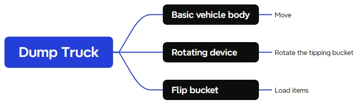
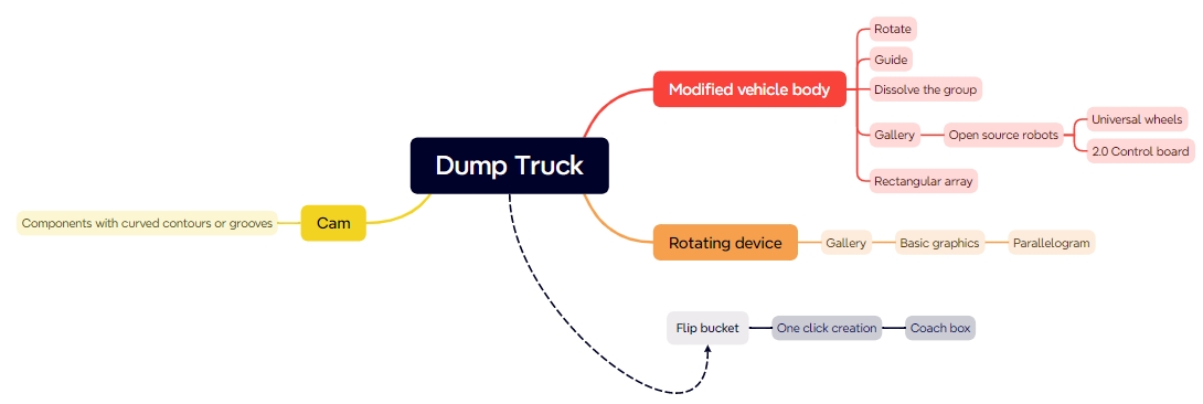
In this STEAM robotics and mechanism project, students upgrade a universal remote-control chassis into a working dump truck using LaserMaker. The lesson connects chassis modification, component layout, TT motor mounting, cam-driven tilting motion, pivot brackets, a dump bed, rubber-band return force, wiring, laser cutting, and hands-on assembly.
This project builds on a basic vehicle body. Students design a dump truck that can carry energy stones, lift the dump bed with a cam mechanism, and return the bed with rubber-band tension after unloading.
| Item | Details |
|---|---|
| Project | Remote-control dump truck with tilting bucket mechanism |
| Software | LaserMaker |
| Main Skills | Opening and modifying an existing chassis file, guidelines, rectangular arrays, alignment, rotating parts, rounded corners, Union, TT motor graphics, cam design, right-angle box creation, laser cutting, wiring, and assembly |
| Suggested Materials | Base vehicle, 2.4G receiver, basswood plywood, dual-axis TT motor, round wooden rod, screws, nuts, rubber bands, and nylon cable ties |
| Classroom Fit | Robotics and mechanism projects, vehicle attachments, cam mechanisms, lifting and unloading systems, remote-control vehicles, maker education, and laser cutting |
Students will modify a universal vehicle chassis, add a dump motor and cam mechanism, design pivot brackets, create a tilting dump bed, laser cut the parts, wire the motors and receiver, and assemble a remote-control dump truck that can transport and unload small objects.
For teachers: Use this lesson to connect vehicle design, mechanical lifting, cam motion, component placement, and iterative testing.
For students: Use the activity to upgrade a basic robot chassis into a task-based vehicle that can carry and unload objects.
For makerspaces: Use it as an advanced add-on project after learners complete a basic remote-control vehicle body.
Modify an existing LaserMaker vehicle chassis file to make room for an additional dump-body mechanism.
Reposition drive motors, receiver board, battery pack, caster wheel, and mounting holes for a new vehicle layout.
Design a dump motor mounting plate, tenons, locking pins, cam, pivot brackets, shaft holes, and matching body mortises.
Create a tilting dump bed using the right-angle box workflow and add support legs, shaft holes, and rubber-band holes.
Assemble the structure, connect the circuit, test the dump action, and identify ways to improve unloading speed and stability.
Design thinking: Turn a basic chassis into a purpose-built dump truck for transporting and unloading energy stones.
Computational thinking: Use measurements, spacing, arrays, alignment references, and copied hole positions to keep parts consistent.
Engineering thinking: Consider motor location, cam size, pivot clearance, shaft alignment, bucket return force, chassis stability, and unloading control.
Students should test powered vehicle mechanisms under teacher or lab supervisor guidance. Keep fingers, loose wires, and small parts away from rotating cams, wheels, the dump bed, and moving shafts during operation.
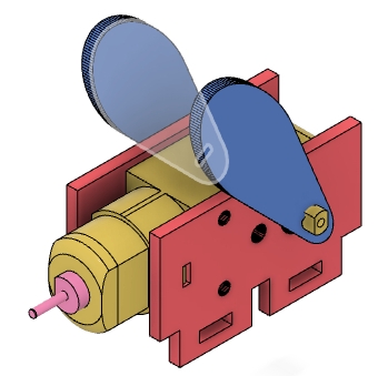
Dump trucks are used to carry and unload materials. In real applications, many dump trucks use hydraulic systems to raise and lower the dump body. In this classroom model, students use an OSROBOT remote-control package, a TT motor, a cam, a pivot shaft, and a rubber-band return system to simulate the basic loading and unloading function.

The model starts from the previously designed universal chassis. Students add a dump body and rearrange the vehicle’s internal layout so the chassis can support the new tilting mechanism.
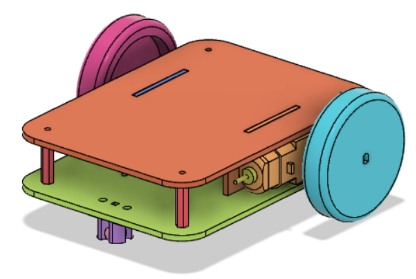
Before modeling the dump truck, students should identify the base vehicle, electronics, sheet material, motor, shaft material, hardware, and elastic return components used in the project.
| No. | Item Name | Quantity |
|---|---|---|
| 1 | Base vehicle | 1 |
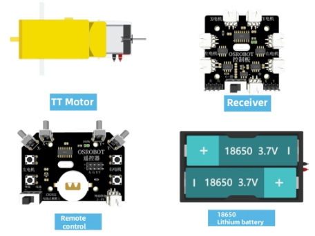
| 2 | 2.4G receiver | 1 |
| 3 | Basswood plywood, 40 cm × 60 cm × 3 mm | 2 |
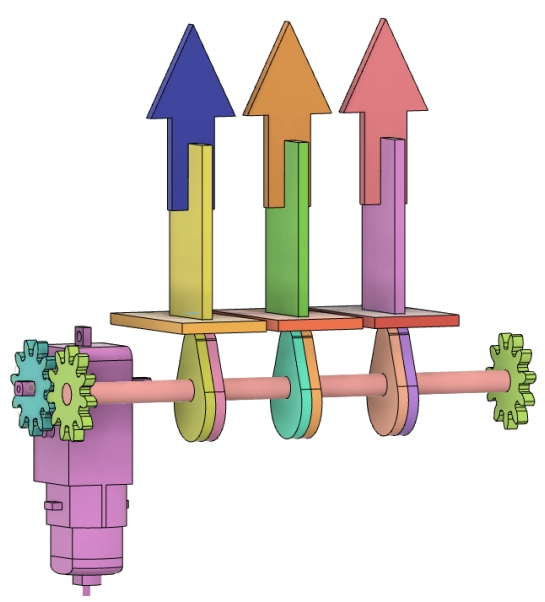
| 4 | Dual-axis TT motor, 1:48 gear ratio | 1 |
| 5 | Round wooden rod | 1 |
| 6 | Screws and nuts | Several |
| 7 | Rubber bands and nylon cable ties | Several |
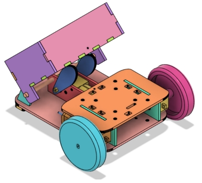
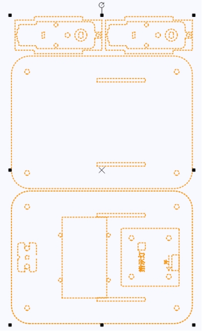
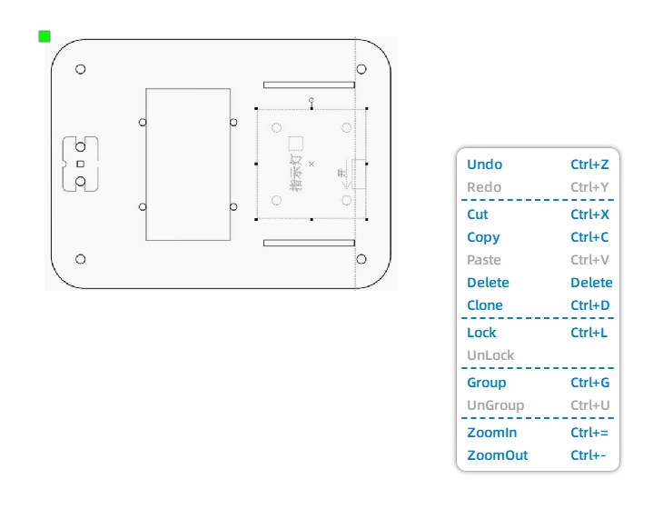
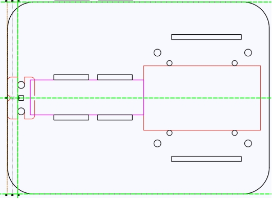
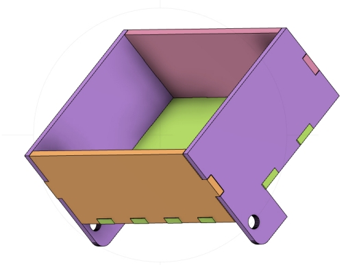
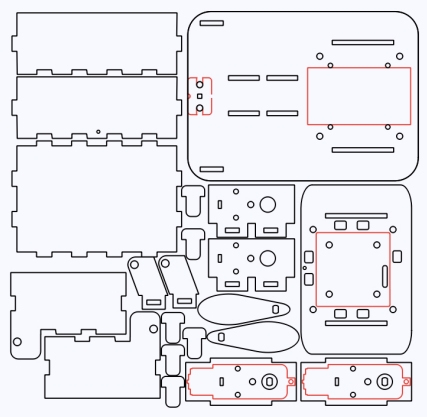
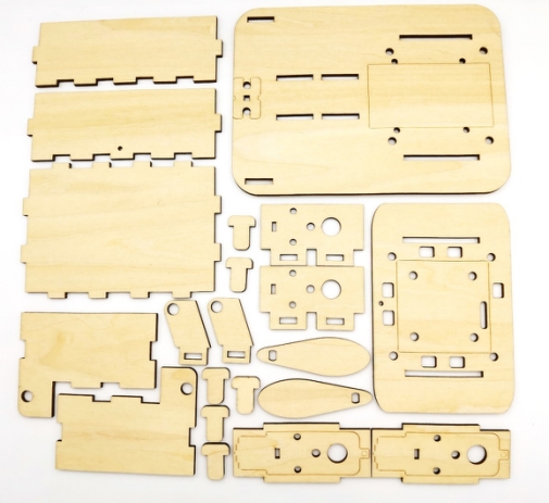
The exterior and mechanism structure is organized into three main groups: vehicle body, pivot bases, and dump bed.
| Part No. | Part Name | Quantity | Function |
|---|---|---|---|
| 1 | Vehicle Body | 1 | Houses motors, batteries, and receiver |
| 2 | Pivot Base | 2 | Supports rotation of the dump bed |
| 3 | Dump Bed | 1 | Carries and unloads small objects |
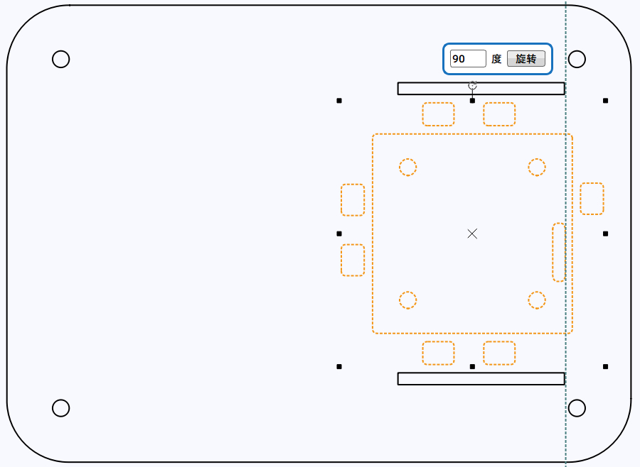
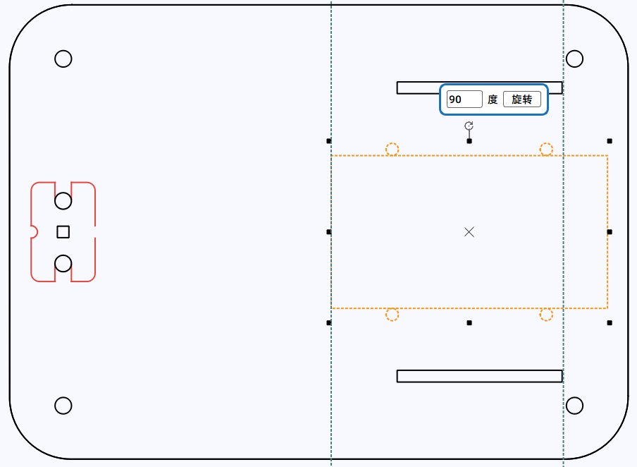
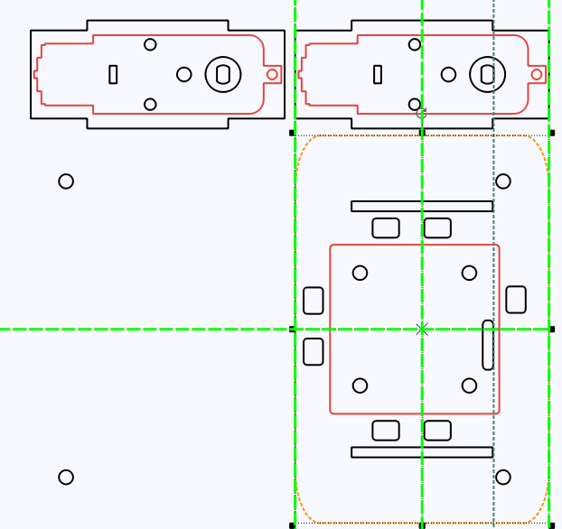
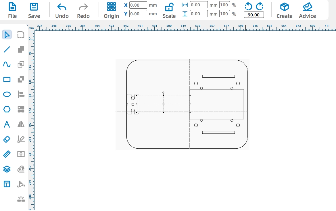
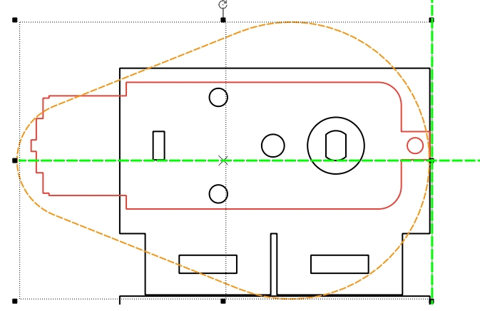
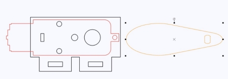
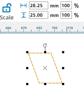
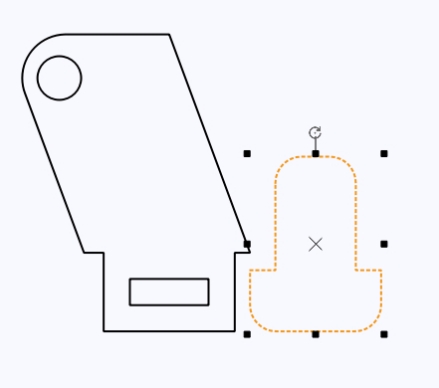
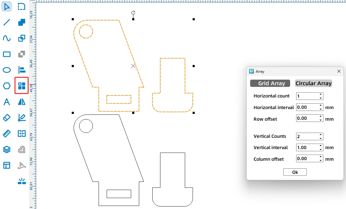
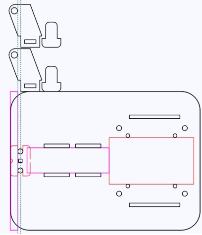
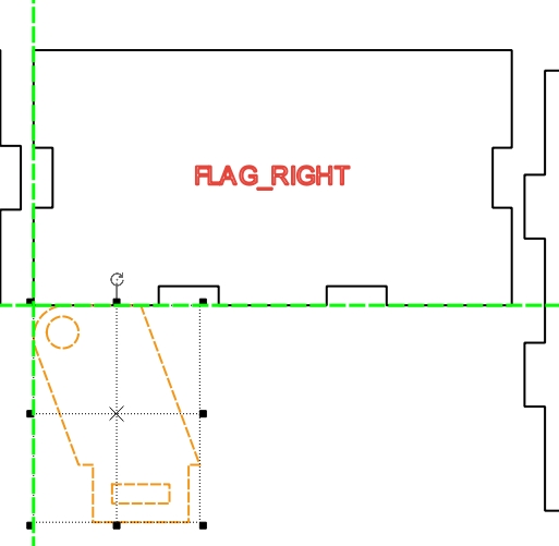
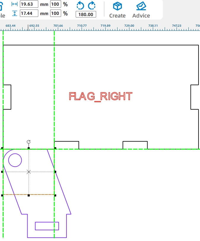
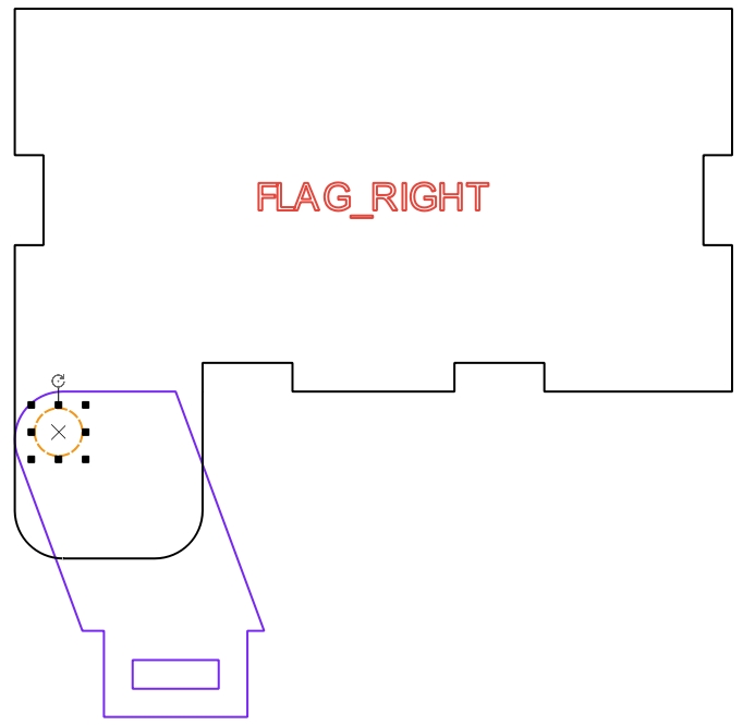
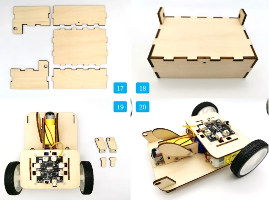
Open the existing CarBody.lcp file in LaserMaker. Rotate the base vehicle drawing by 90 degrees and place it horizontally to make the new design work easier.
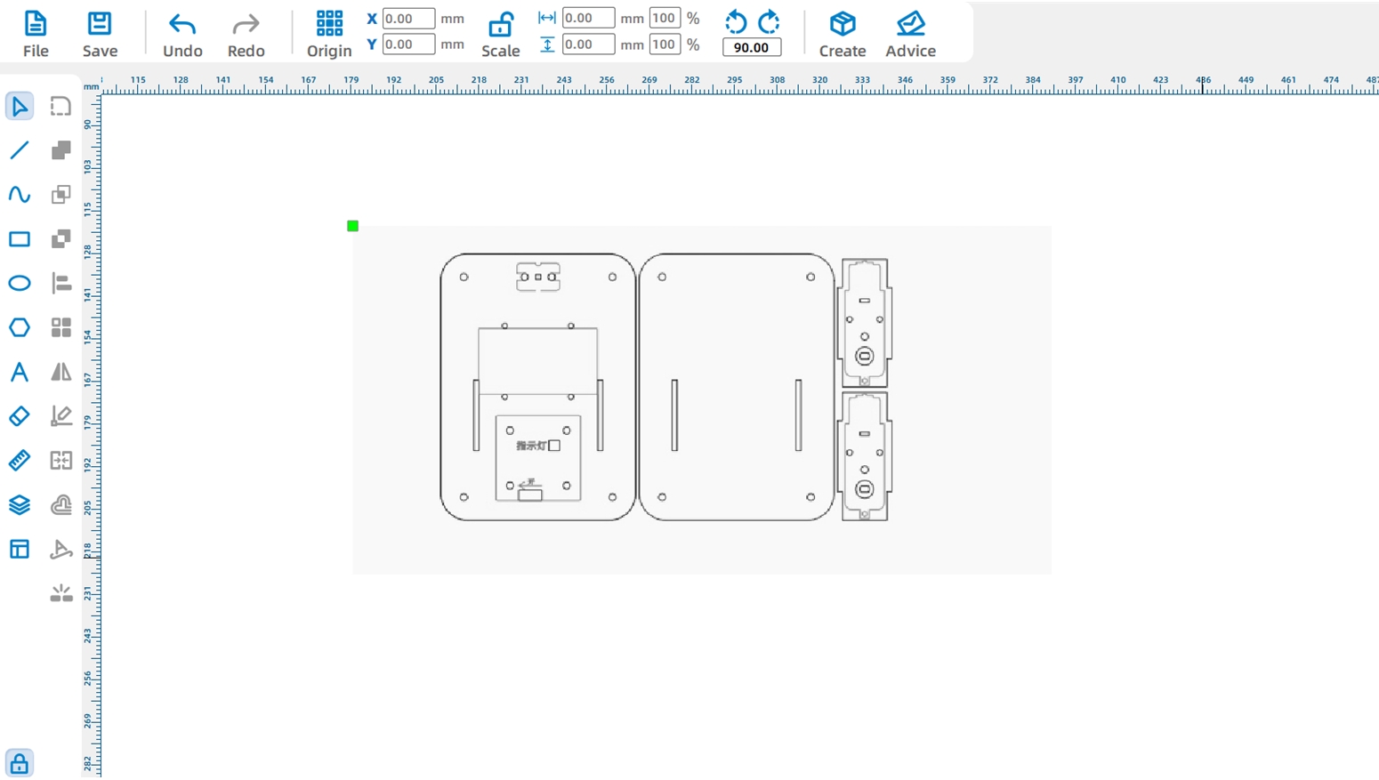
Because the added tilting motor needs to sit on the bottom panel, move the original drive motor mounting positions to create enough space. Use LaserMaker guidelines to align the mortises for the motor mounting plates.
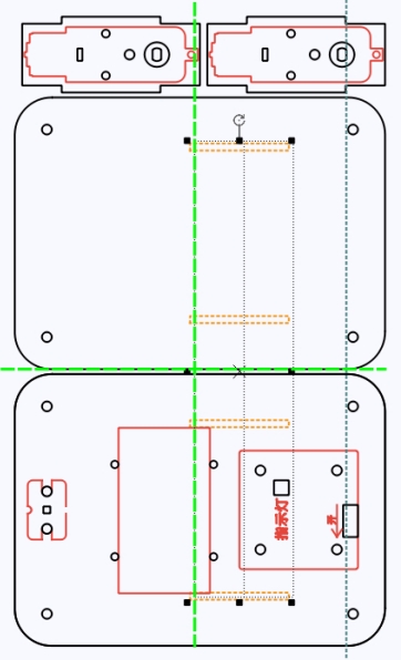
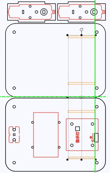
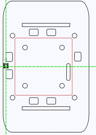
Next, move the receiver board to the top panel for easier operation. Delete the original control board graphic, then add the 2.0 Control Board External graphic from the Open-Source Robot Hardware library. Align it with the motor mounting plate holes and rotate it so the power port faces the rear of the car body.
Move the battery component to the bottom panel. Rotate it into a horizontal position and align it with the motor mounting plate holes.
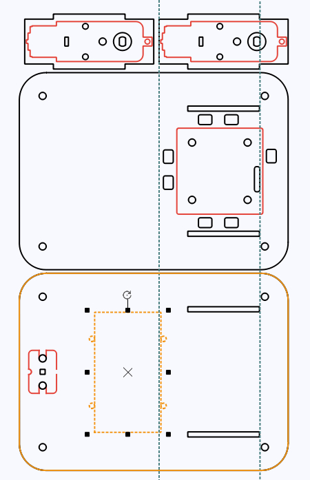
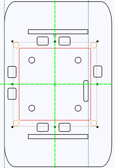
Shorten the top panel to leave space for the tilting motor. After changing the top panel size, delete the original nylon standoff holes and redraw them using the control board as a reference.
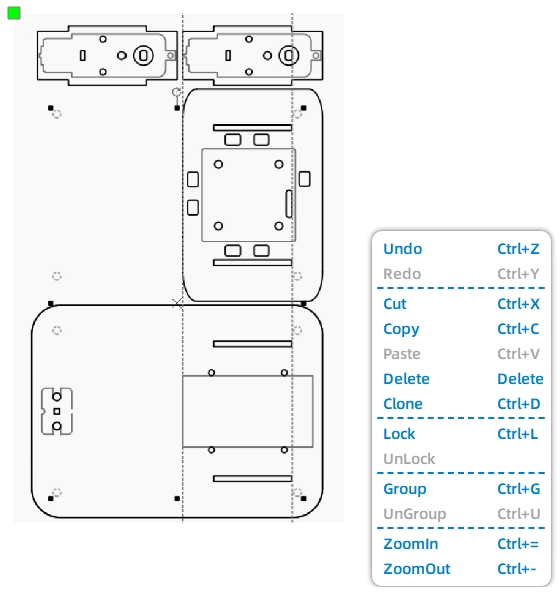
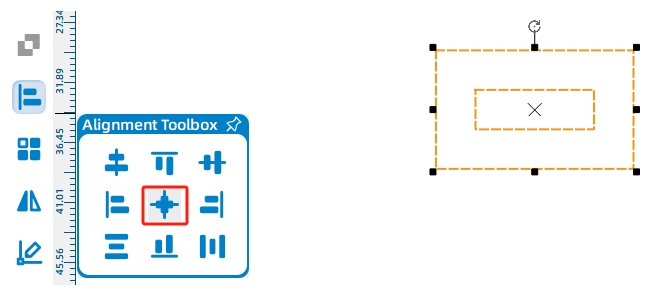
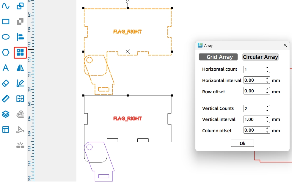
Group the four standoff holes, align them with the control board on the top plate, then copy the matching hole set to the bottom plate using shared mortise positions as a reference.
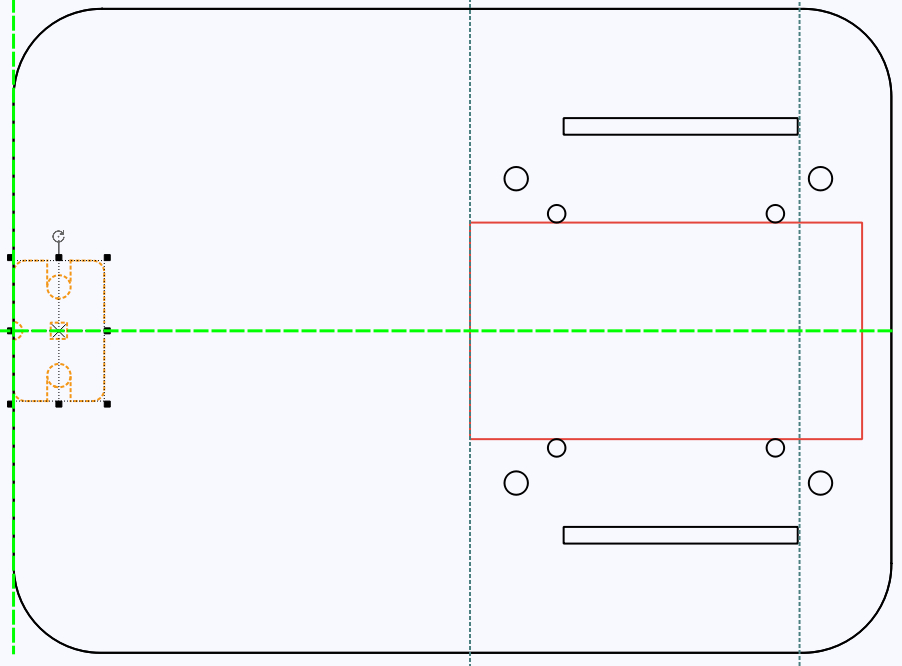
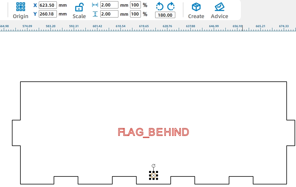
Finally, move the caster wheel graphic to the front end of the bottom panel so the caster wheel screws do not interfere with the dump motor installation.
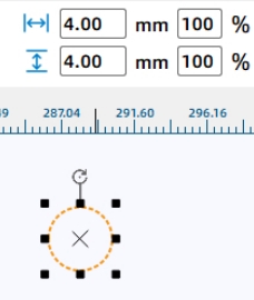
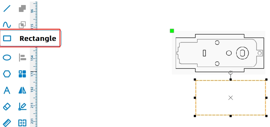
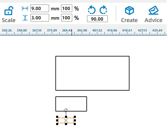
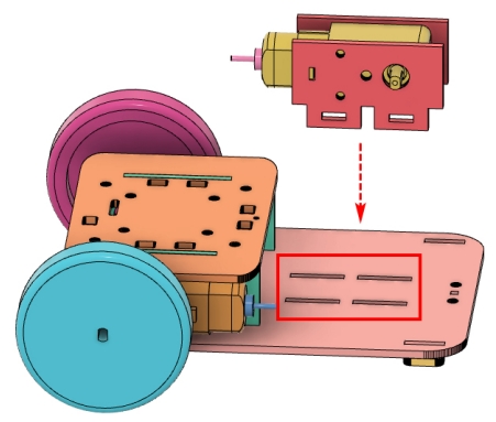
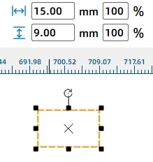
The tilting mechanism uses a motor and cam to lift the dump bed. First, draw a 65 mm by 20 mm motor cross-section reference and place it beside the battery component. Change it to a reference color so students can clearly distinguish it from final cutting lines.
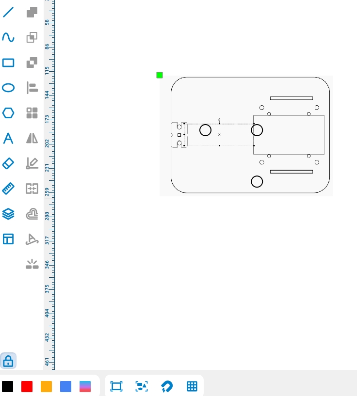
Draw the dump motor mounting plate as a 56 mm by 25 mm rectangle. To keep the vehicle visually consistent, the mounting plate height matches the height of the drive motor mounting plates.
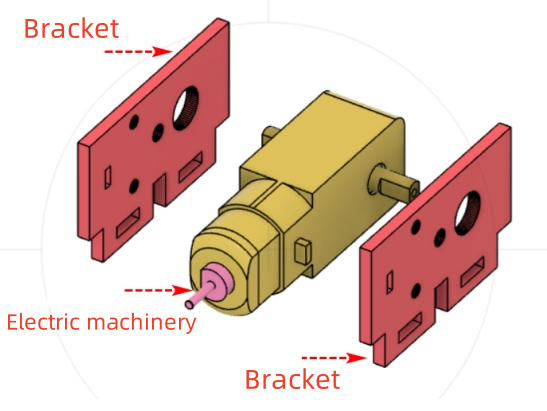
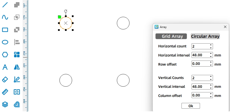
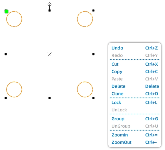
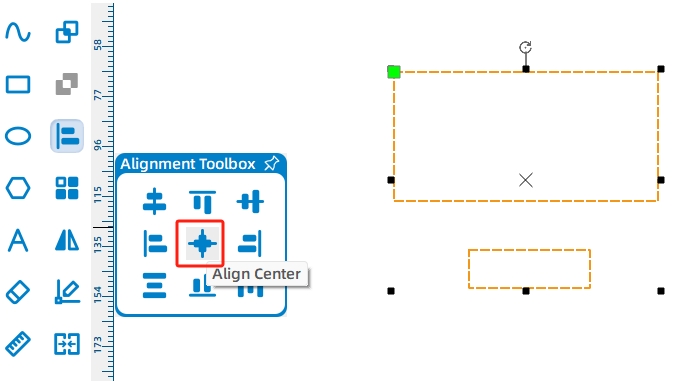
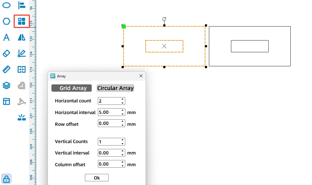
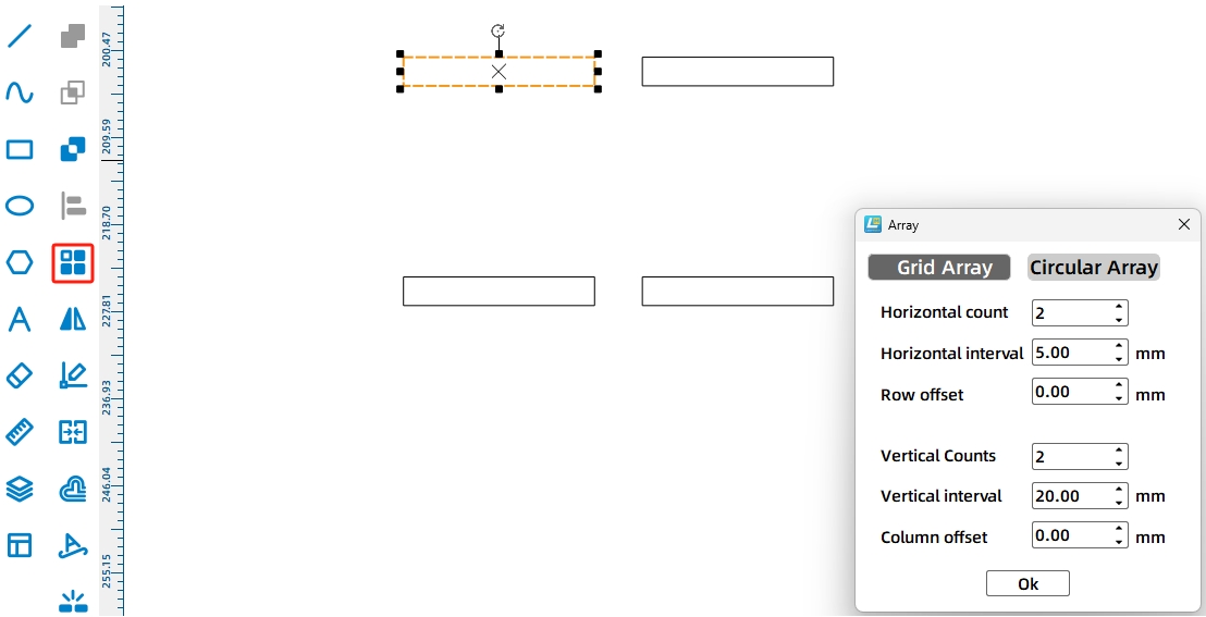
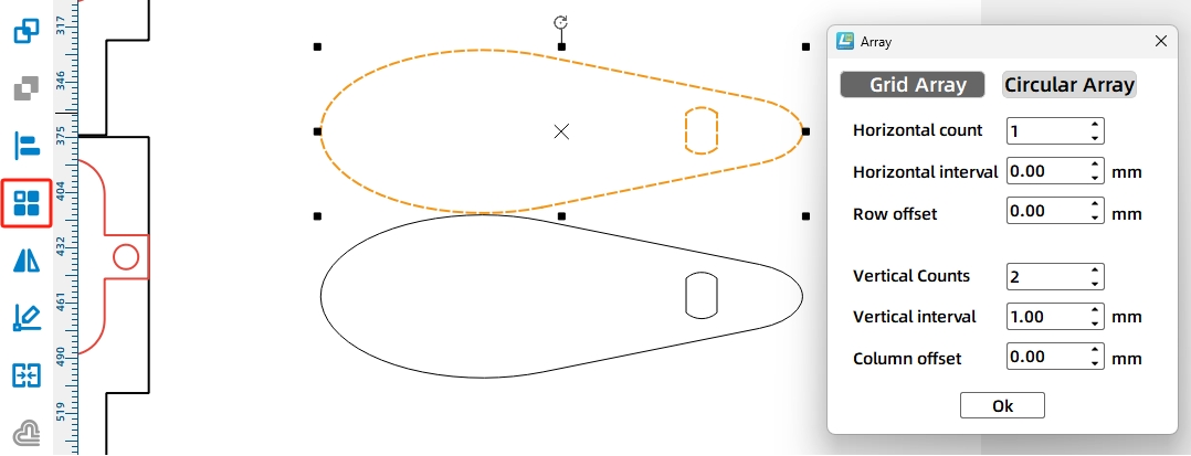
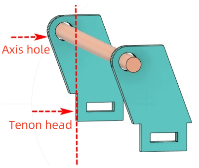
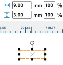
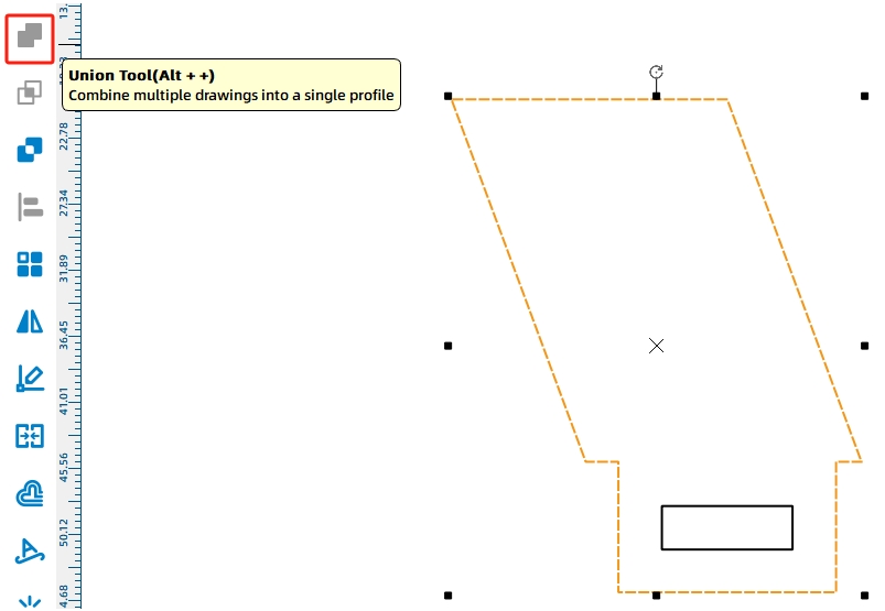
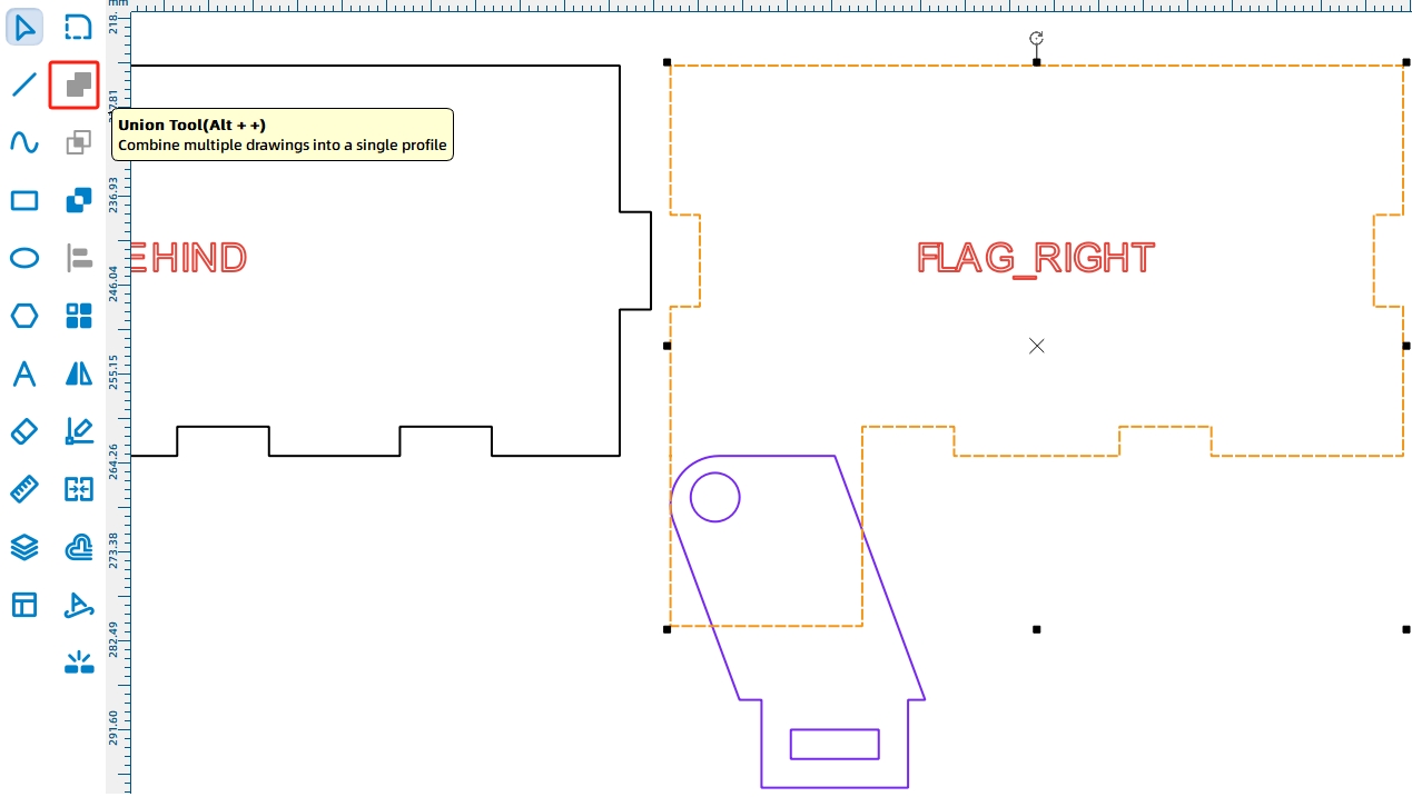
The dump motor mounting plate is installed through holes in the bottom panel and locked with tenon pins. Draw a 20 mm by 9 mm tenon and a 9 mm by 3 mm mortise, align them, then create two tenon features with a rectangular array. Merge the tenons with the mounting plate using Union.
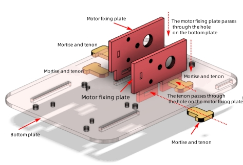
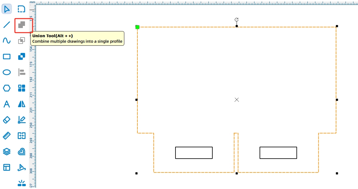
Add the TT Motor graphic from the Open-Source Robot Hardware library to define the motor shaft and mounting holes. Because the dump motor needs reliable support, duplicate the fixed plate so the motor can be held from both sides.
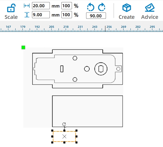
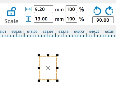
The motor mounting plates are locked with T-shaped tenon pins. To improve fit, the source workflow increases the tenon width by 0.2 mm for laser compensation.
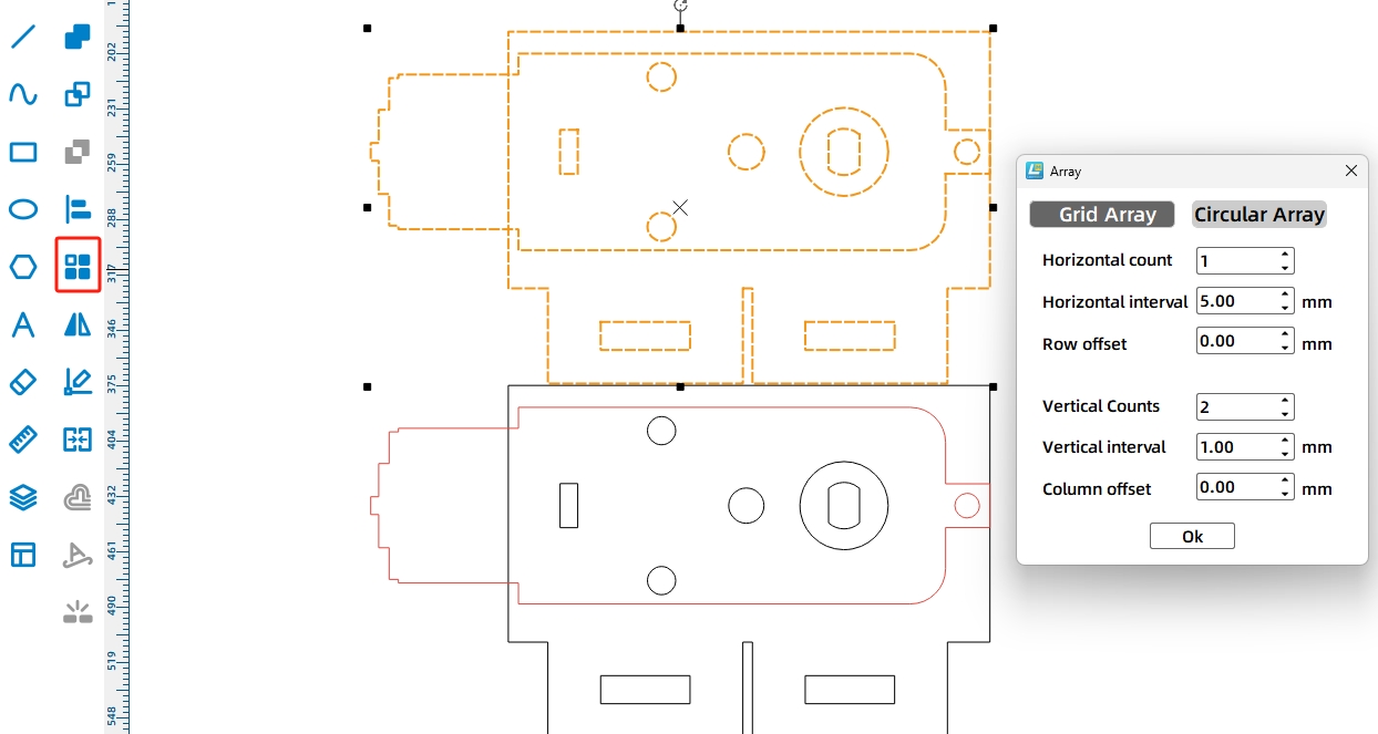
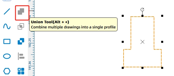
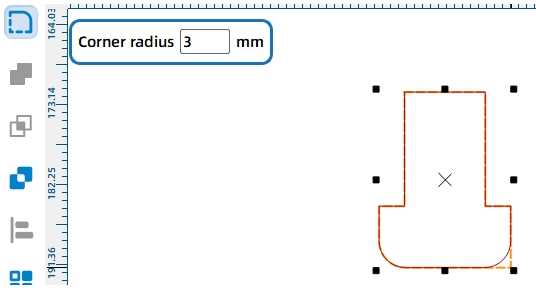
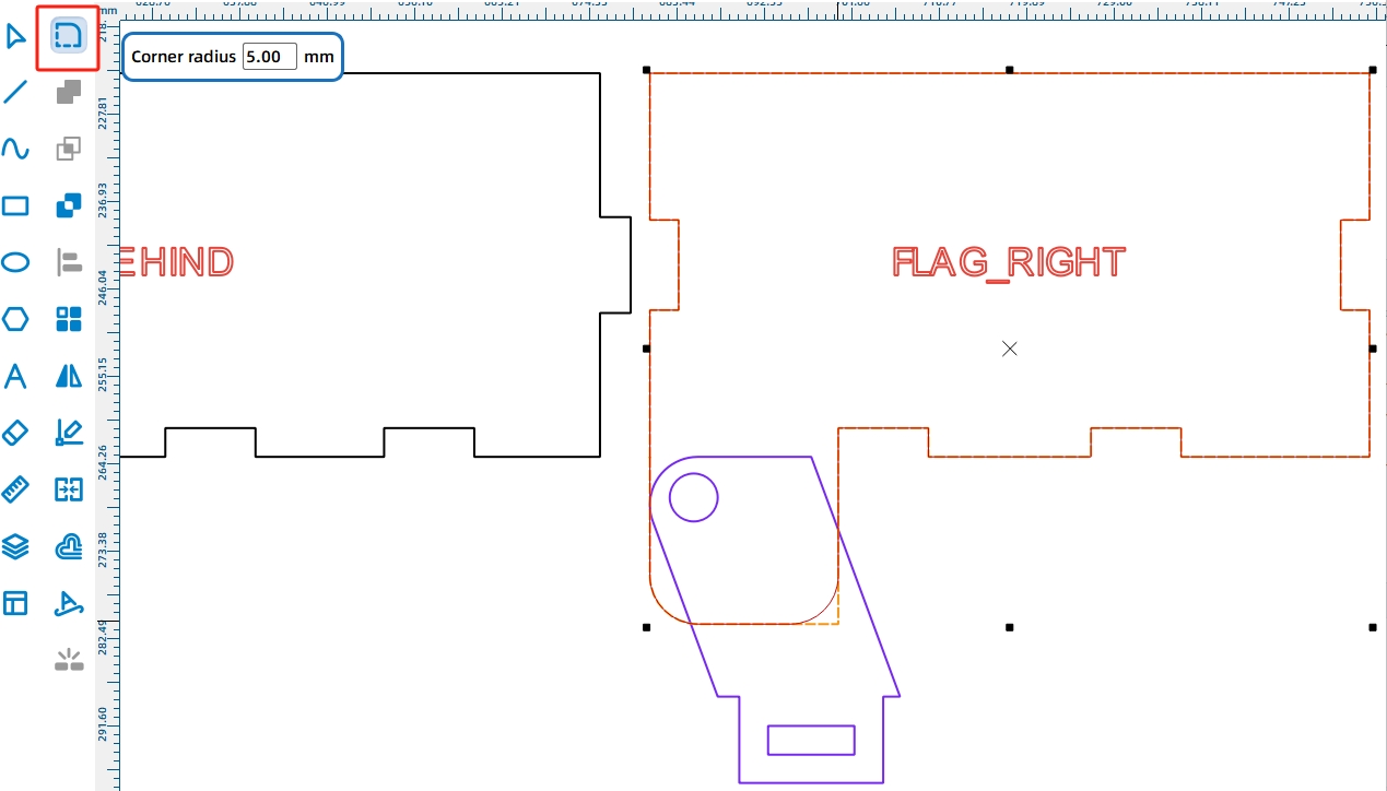
Draw a 9.2 mm by 13 mm rectangle for the tenon and a 15 mm by 6 mm rectangle for the cap. Align the two shapes, merge them with Union, and round the corners with a 3 mm radius. Use Rectangular Array to duplicate the required pins.
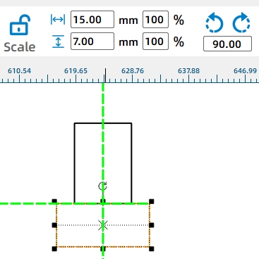
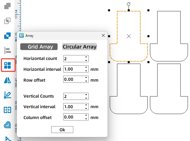
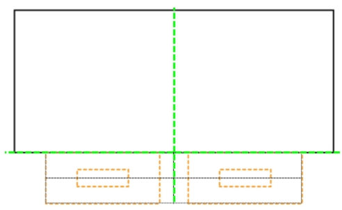
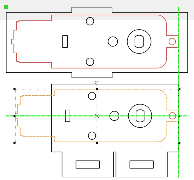
Next, draw the corresponding mounting holes on the vehicle body. Use the mounting plate tenons as a reference. Draw a 20 mm by 3 mm rectangle, then use Rectangular Array with the same tenon spacing to create the required body mortises.
The cam lifts the dump bed. A longer cam can raise the bucket higher, but the source workflow limits the cam size based on the available motor and mounting-plate space. The cam length should not exceed the TT motor length, and the cam height should not exceed the 25 mm mounting plate height.
Select the Cam graphic from Mechanical Parts, place it in the fixed panel, and resize it to 60 mm by 20 mm. Rotate the cam by 180 degrees so the larger arc side contacts the dump bed for smoother lifting.
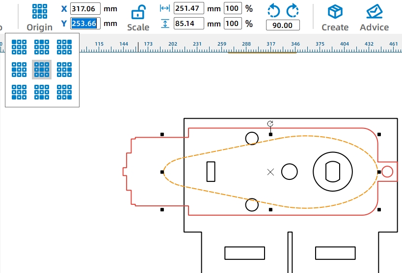
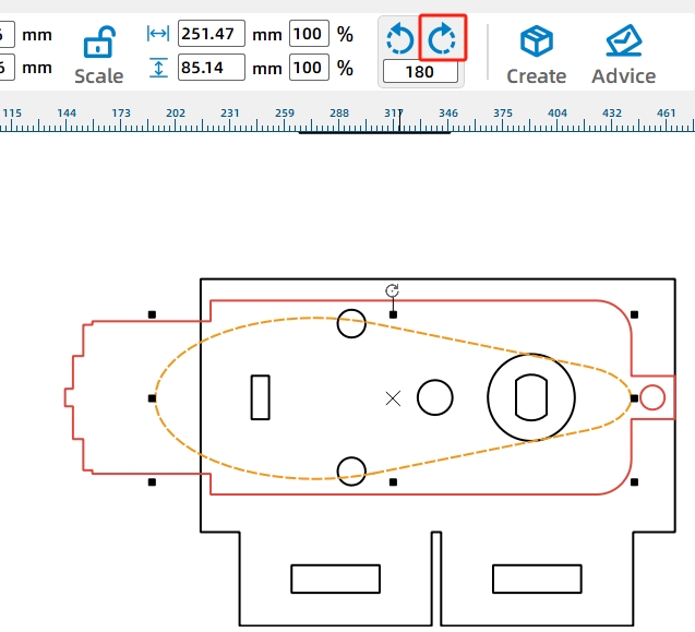
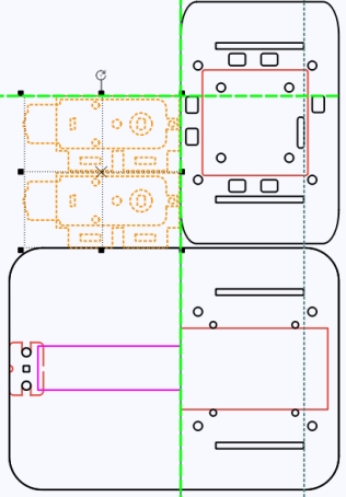
Move the TT motor hole and cam outside the fixed panel, then duplicate the finished cam with the TT motor hole.
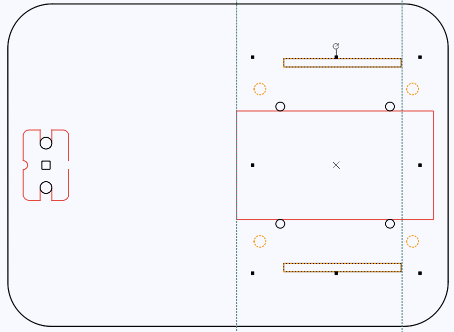
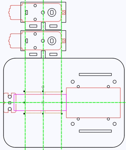
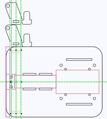
The rotating shaft assembly allows the dump bed to flip. When the dump motor rotates the cam, the cam pushes the dump bed around a round wooden rod. The rod is held by pivot brackets on the vehicle body.
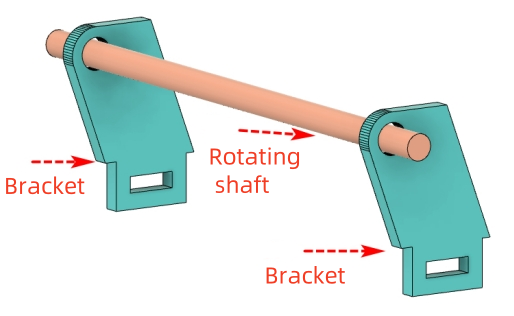
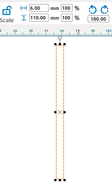
Draw a 6 mm by 110 mm rectangle as a round-rod cross-section reference on the base plate. This helps locate the pivot bracket and shaft hole.
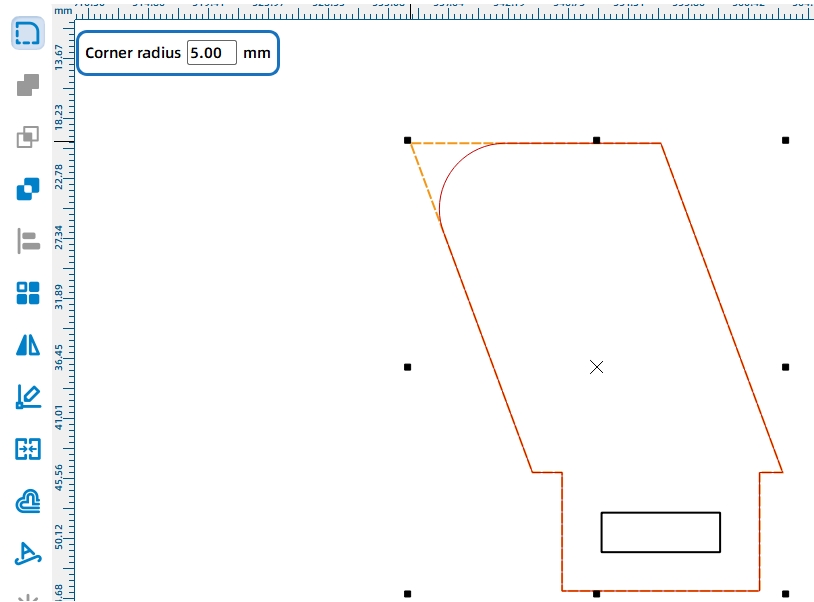
Use a parallelogram as the pivot bracket so the shaft hole can extend outward and reduce friction between the round rod and the dump motor. Flip the parallelogram horizontally, set its height to 25 mm, then add a bottom tenon with a through-mortise.
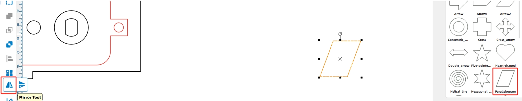
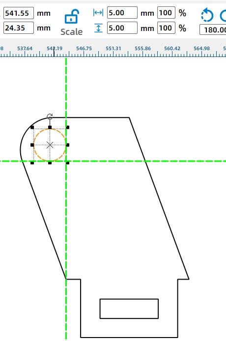
Round the upper corner of the pivot bracket with a 5 mm radius so the dump bed can flip more smoothly. Add a 6 mm shaft hole near the upper-left corner, then duplicate the pivot bracket set for both sides of the vehicle.
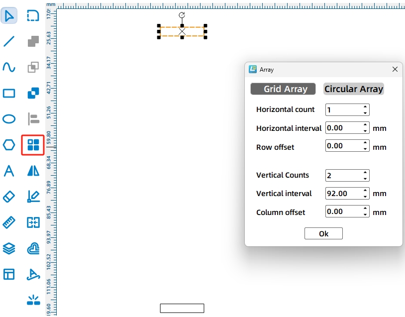
Draw matching 15 mm by 3 mm mortises on the vehicle body for the pivot brackets. The source workflow sets the distance between the two mortises to 92 mm and places each mortise 6 mm from the vehicle edge for stability.
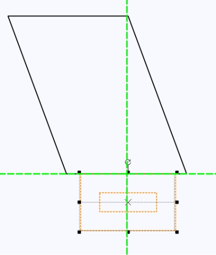
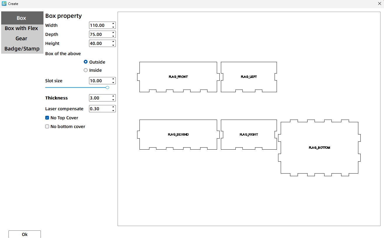
The dump bed needs to fit on the vehicle body and carry a hollow cube-shaped energy stone. The source workflow notes that the base vehicle is 150 mm wide and 110 mm high. After checking the top panel width, the maximum dump-bed base is calculated, and the final dump bed is set to 75 mm wide and 40 mm high for easier unloading.
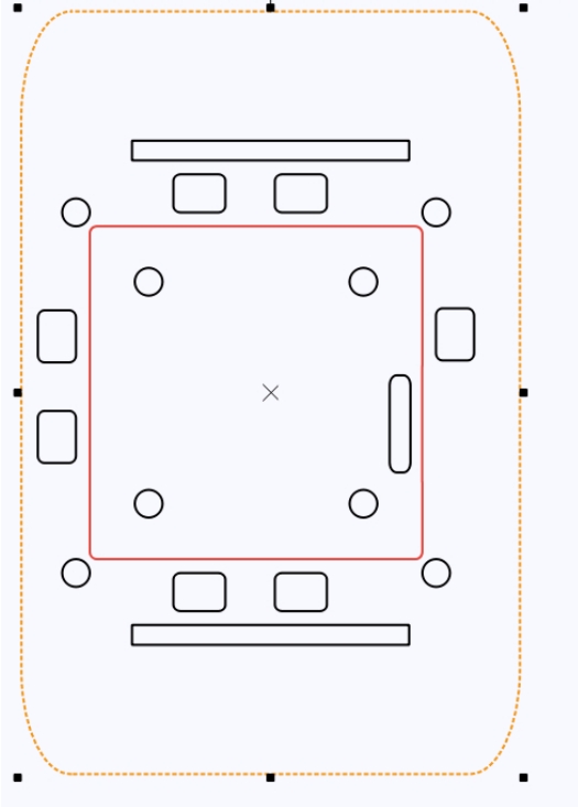
The dump bed connects to the round shaft through support legs on the left and right panels. Copy a pivot bracket as a reference, change it to a reference color, and place it beside the dump bed side panel. Draw the support leg, merge it with the side panel, then round the lower corners.
Apply the shaft hole from the pivot bracket reference to the dump bed support leg. Then duplicate the side panel and shaft hole for the other side of the dump bed.
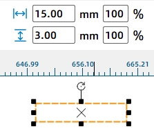
Because the dump bed may not return by gravity alone after being lifted by the cam, the source workflow adds rubber-band holes. Draw 2 mm holes on the dump bed and the vehicle body so the rubber band can pull the dump bed back after unloading.
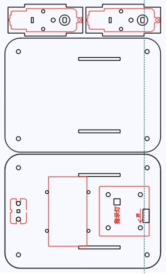
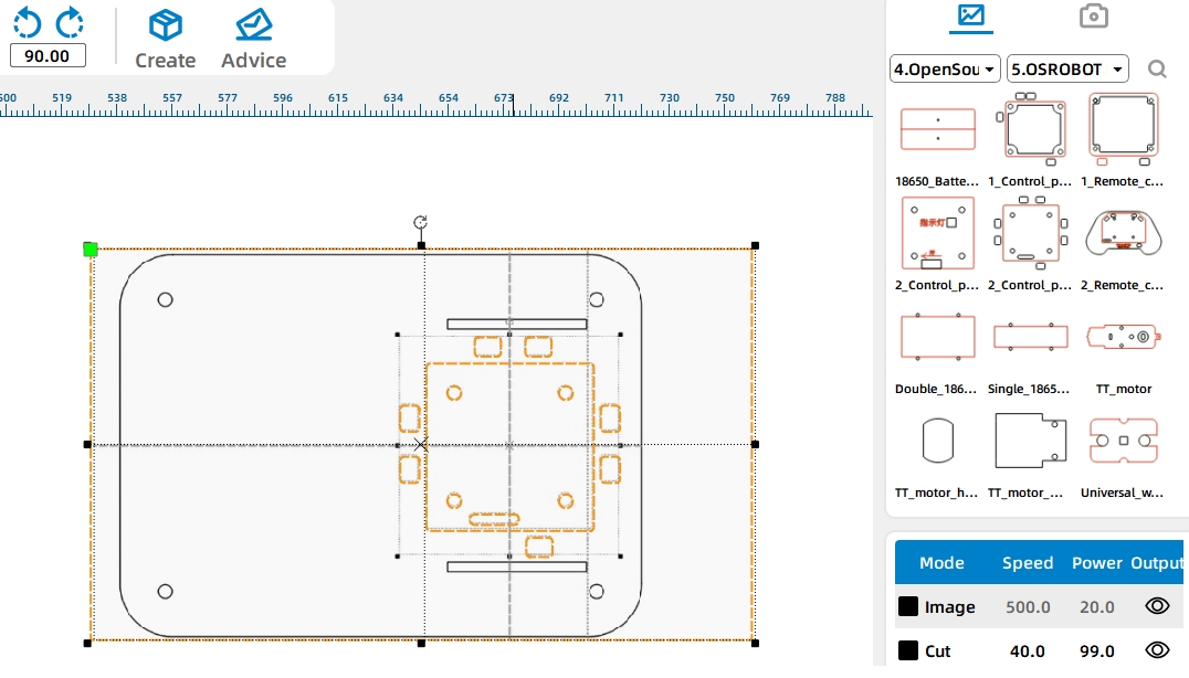
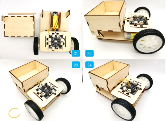
After the design is complete, delete unnecessary auxiliary lines and references. Arrange the final parts to improve plywood usage, then check the marking and cutting parameters for the selected material. When the parameters are confirmed, send the file to the laser cutter and begin processing from the machine panel.
Connect the circuit according to the wiring diagram. Since the dump body should not tilt too quickly, the source workflow uses a TT motor with a 1:220 gear ratio for the third motor.
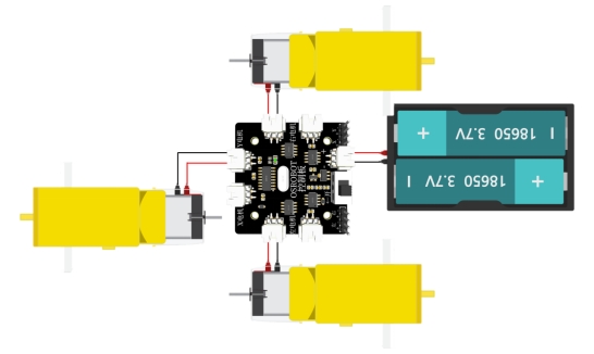
Begin by securing the batteries to the vehicle base with cable ties. Install the driving motors onto their mounting plates, then secure the mounting plates to the vehicle base.
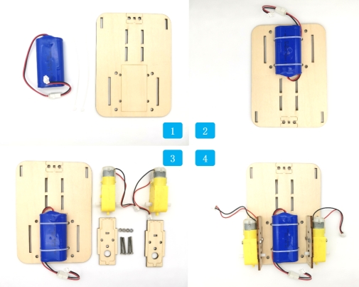
Install the third motor onto its mounting plate and secure it to the vehicle base. Add the hexagonal columns and fix them to the corresponding base plate holes.
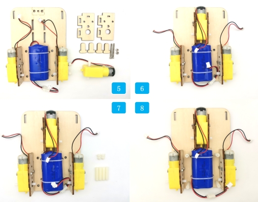
Fix the control board to its mounting plate. Thread the electronic component wires through the top plate, connect them to the control board, and then fix the top and bottom plates of the vehicle body together.
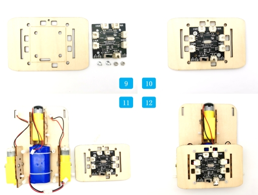
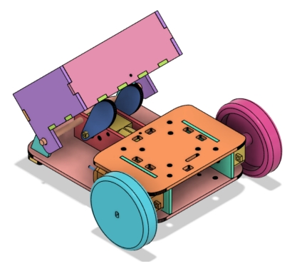
Install the caster wheel at the front of the vehicle and add the tires to the drive motor shafts. Then install the cam onto the third motor shaft and thread the rubber band through the circular hole on the top plate.
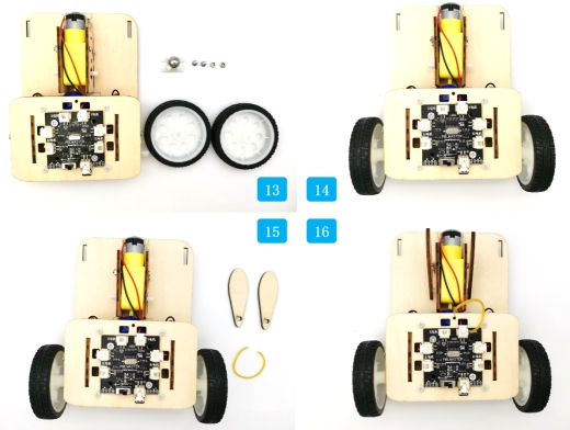
Assemble the front, rear, left, right, and bottom panels of the dump bed. Install the pivot bases at the front end of the vehicle body.
Place the dump bed outside the pivot bases and secure it with the round wooden rod. Attach the rubber band to the dump bed and vehicle body so the bed can return after the cam releases it.
Check whether the driving motors, receiver, battery, and dump motor are securely installed before testing.
Confirm that the cam rotates without hitting the base plate, wires, or dump bed supports.
Test whether the dump bed pivots smoothly on the round wooden rod.
Adjust the rubber band if the dump bed does not return reliably after unloading.
Observe whether the vehicle can carry and unload objects without tipping, dragging wires, or moving too quickly.
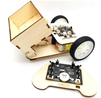
After design, laser processing, wiring, and assembly, students complete a remote-control dump truck. The project gives students practical experience with modifying existing drawings, using references for modeling, applying rectangular arrays, rounding corners, aligning parts, and building a motorized tilting mechanism.
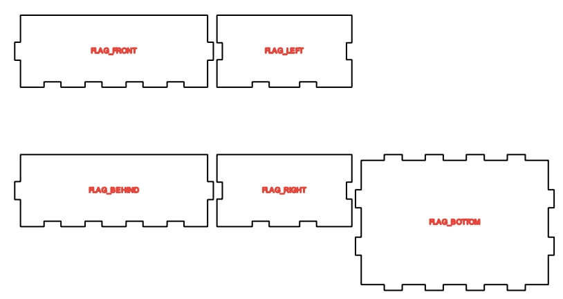
The dump truck uses LaserMaker’s right-angle box function to create the dump bed. As an extension challenge, students can redesign the dump bed shape, improve the unloading angle, or create a more stable bucket for different object sizes.
The source workflow also notes that even with a low-speed motor, the dump bed may unload quickly due to inertia. Students can investigate ways to slow down the action, such as changing cam shape, adjusting rubber-band tension, modifying the pivot position, reducing load mass, or redesigning the linkage.
This project is suitable for classroom laser cutters that support cutting and marking of sheet materials for robotics and mechanism projects. For schools, makerspaces, and beginner STEAM labs, projects like remote-control dump trucks, vehicle attachments, cam-driven mechanisms, and laser-cut robot upgrades can be completed with a classroom laser cutter such as the Thunder Laser Bolt Series.
Teachers can choose the machine and material setup based on classroom space, project size, material thickness, electronic components, moving-part clearance, and learning goals. The same LaserMaker workflow can also be adapted for other CO2 laser machines when students move on to more advanced vehicle mechanisms or competition-style robot tasks.
Talk To Our Experts Now!
Please leave your contact information so that we can serve you better.
TAKE THE NEXT STEP WITH THUNDER LASER

 Stable & Consistent MachinesUnlimited ApplicationRobust After-sales SupportFactory Direct Supply


