


Remote-Control Crane Laser Cutting STEAM Project with LaserMaker
 24-08-09
WHAT ARE YOU LOOKING FOR?
Search Across Products, Blog Posts, Support Content, And Resources.

Remote-Control Crane Laser Cutting STEAM Project with LaserMaker
24-08-09

In this STEAM robotics and mechanism project, students upgrade a basic remote-control vehicle chassis into a working crane using LaserMaker. The lesson connects real-world crane structures, winch design, gear reduction, boom support, hook design, cable routing, laser-cut cross shafts, wiring, and hands-on assembly.
This project builds on previous base-vehicle lessons. Students focus on the lifting structure: a motor-driven winch reels the cable in and out, the boom guides the lifting direction, and the hook raises or lowers the energy stone.
| Item | Details |
|---|---|
| Project | Remote-control crane with winch, boom, and hook |
| Software | LaserMaker |
| Main Skills | Rectangle Tool, Ellipse Tool, Modular Gear, TT Motor graphics, cross-shaft design, Rectangular Array, Union, Difference, alignment, gear transmission, cable routing, laser cutting, wiring, and assembly |
| Suggested Materials | Basic vehicle model, 2.4G receiver, TT motors, lithium battery, basswood plywood, M3 screws and nuts, copper columns, R3080 nylon rivets, and cable ties |
| Classroom Fit | Robotics and mechanism projects, gear transmission, pulleys, winches, lifting systems, remote-control vehicles, maker education, and laser cutting |
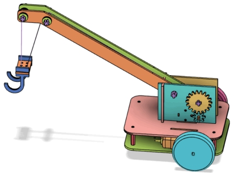
Students will design and build a crane lifting structure that can be mounted onto a basic vehicle chassis. They will create a winch, gear reduction system, boom, hook, cross shafts, sleeves, and support brackets, then laser cut and assemble the parts to test lifting and lowering motion.
For teachers: Use this project to connect real crane systems with gear transmission, winch drums, fixed-pulley ideas, cable motion, and mechanical lifting.
For students: Use the activity to turn a mobile robot chassis into a crane that can lift, carry, and lower small objects.
For makerspaces: Use it as an advanced robotics add-on project after learners complete a basic remote-control vehicle body.
Analyze a crane as a system made from a mobile base, winch, boom, hook, cable, and support structure.
Use a small gear and large gear to reduce the winch speed and make lifting movement easier to control.
Create motor mounting plates, boom support boards, cross shafts, axle sleeves, boom plates, and hook parts in LaserMaker.
Apply alignment, Union, Difference, Rectangular Array, modular gear generation, and cross-hole design to create accurate laser-cut parts.
Assemble the crane, route the lifting rope, connect the motor, and test how the winch changes the hook height.
Design thinking: Turn a lifting challenge into a practical crane attachment that can move energy stones from a low area to a higher energy center.
Computational thinking: Use gear tooth counts, shaft-hole dimensions, spacing, arrays, cable paths, and part alignment to make the mechanism repeatable.
Engineering thinking: Consider lifting speed, hook weight, boom angle, cable direction, axle stability, gear meshing, friction, and balance on the base chassis.
Students should test lifting mechanisms under teacher or lab supervisor guidance. Keep fingers, loose wires, and small parts away from rotating gears, winch drums, shafts, wheels, and the lifting cable during operation.
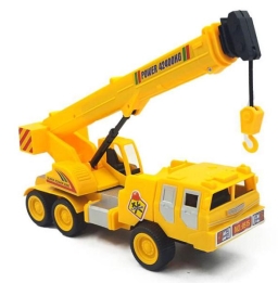
Cranes are used in ports, construction sites, warehouses, and other places where heavy objects need to be lifted, moved, and unloaded. A wheeled crane can move between locations, while a tower crane is often fixed in place on a construction site.
In this project, students focus on the lifting structure. The basic vehicle chassis handles movement, while the crane mechanism handles lifting and lowering. The lifting structure includes a winch, boom, and hook.
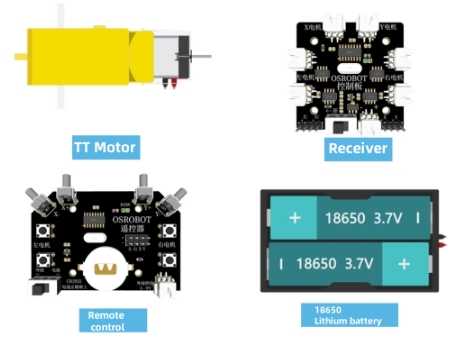
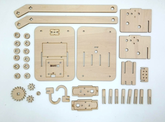
Before modeling the crane, students should identify the vehicle base, electronics, motors, sheet material, fasteners, rivets, and cable-management parts used in the project.
| No. | Name | Quantity |
|---|---|---|
| 1 | Basic vehicle model, for reference | 1 |
| 2 | 2.4G receiver | 1 |
| 3 | TT motor, 1:220 gear ratio | 3 |
| 4 | 7.4V lithium battery | 1 |
| 5 | Basswood plywood board, 40 cm × 60 cm × 3 mm | 1 |
| 6 | M3 flathead screws, nuts, and copper columns | Several |
| 7 | R3080 nylon rivets | 2 |
| 8 | Cable ties | 2 |
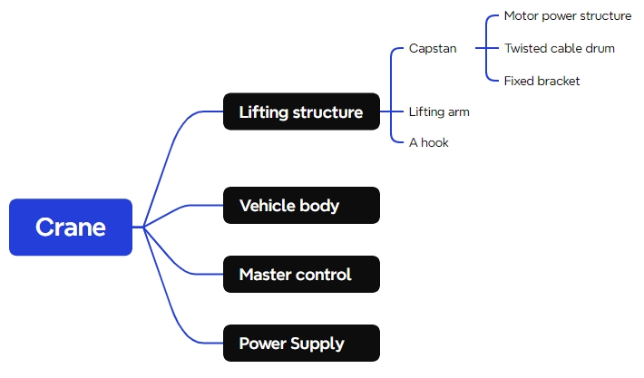
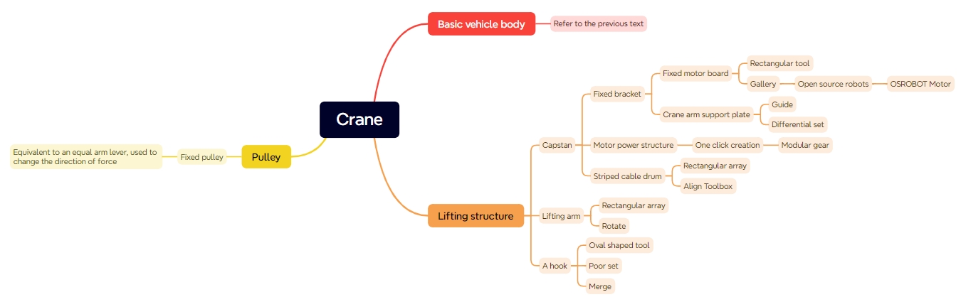
The crane model is organized into four functional groups: winch, boom, hook, and base chassis.
| Part No. | Name | Quantity | Function |
|---|---|---|---|
| 1 | Winch | 1 | Fixes the boom and adjusts the lifting rope length by rotating, allowing the hook to rise or descend. |
| 2 | Boom | 1 | Extends outward to position the hook over the object being lifted. |
| 3 | Hook | 1 | Connects to the object being lifted. |
| 4 | Base Chassis | 1 | Allows the crane to move from one location to another. |
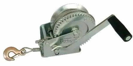
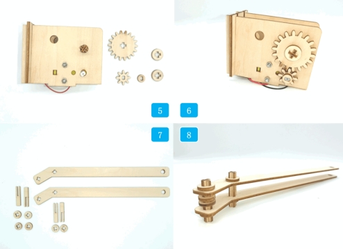
The winch controls the release and retrieval of the lifting rope. In this classroom crane, the winch includes a motor drive structure, cable drum, and fixed bracket. A reduction gear system is added so the lifting rope does not move too quickly.
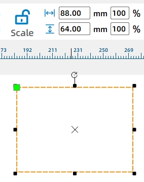
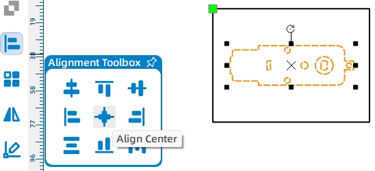
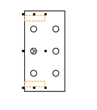
Start with the motor fixing plates. Draw an 88 mm by 64 mm rectangle. Add the TT Motor graphic from the Open-Source Robotics Hardware library, group it, and align it to the center-bottom of the rectangle.
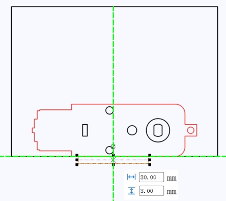
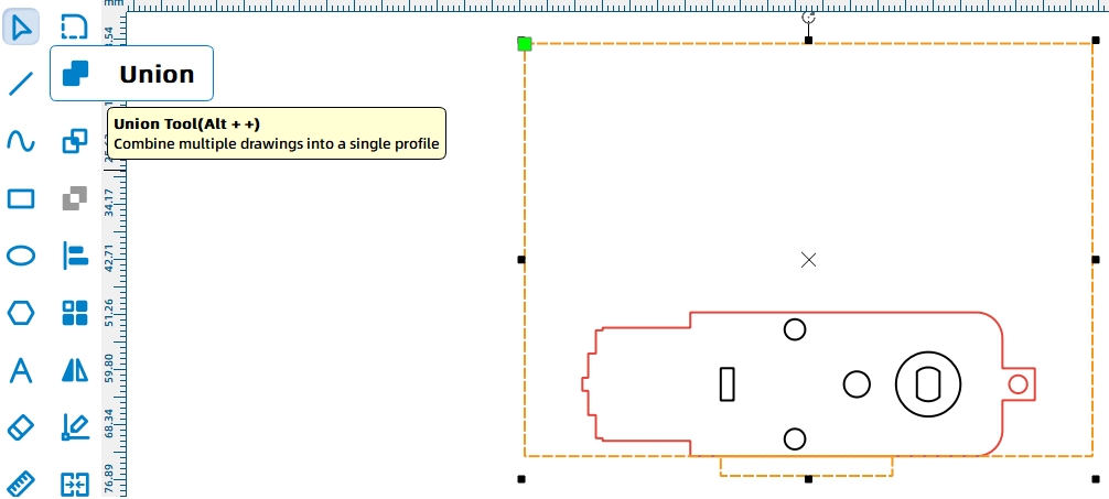
Add a 30 mm by 3 mm tenon at the bottom of the motor fixing plate so it can be installed on the base chassis. Use Union to merge the tenon with the fixing plate.
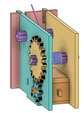
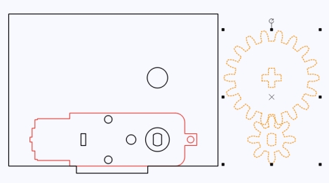
Use LaserMaker’s Modular Gear function to create a small gear and a large gear. In the source workflow, the small gear uses 8 teeth, the large gear uses 18 teeth, and the gear module is set to 2. The small gear connects to the motor shaft, and the large gear connects to the cable drum.
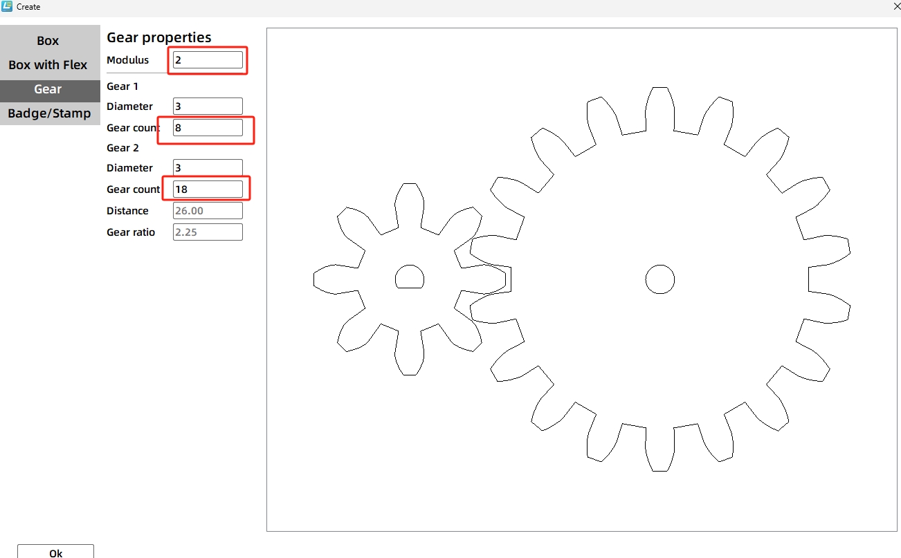
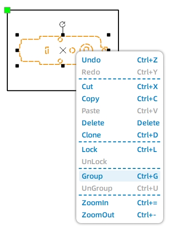
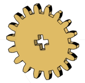
Replace the small gear’s default center hole with a TT motor shaft hole. For the large gear, create a cross-shaped shaft hole by drawing two 2.7 mm by 8 mm rectangles, rotating one by 90 degrees, aligning them, and merging them with Union.
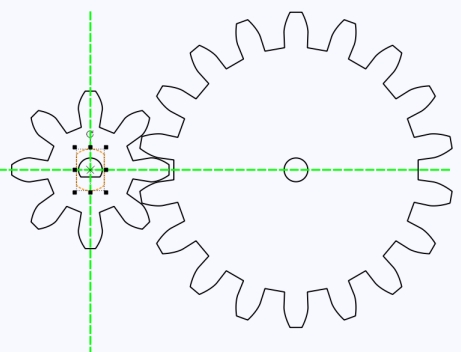
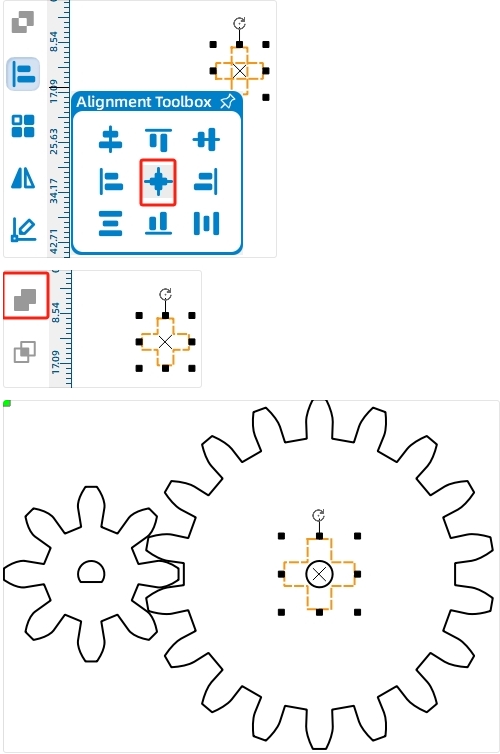
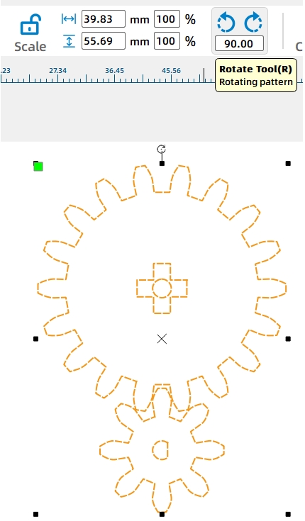
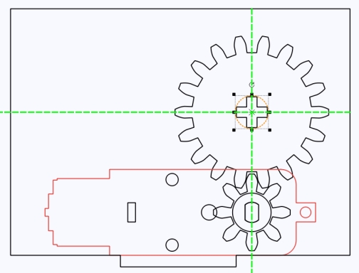
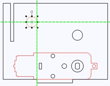
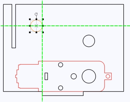
Rotate the gear set so the small gear sits below the large gear. Align the small gear with the TT motor shaft hole on the motor fixing plate. Then draw an 8.6 mm circular clearance hole on the fixing plate around the cross shaft position.
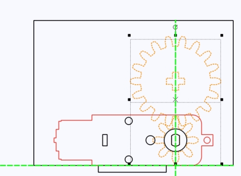
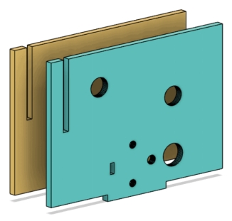
The motor fixing plate also needs to connect with a perpendicular boom support board. Draw a 2.7 mm by 32 mm mortise near the motor side using a guideline for placement, then use Difference to create the slot.
Add an 8.6 mm circular hole to the right of the mortise slot. This hole helps connect the fixing plate to the boom structure. Duplicate the finished fixing plate so the motor can be supported on both sides.
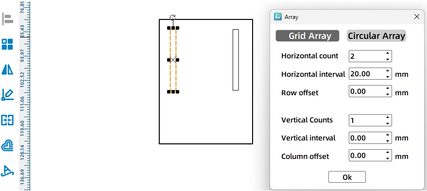
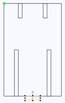
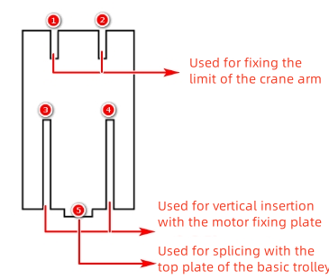
The boom support board is installed vertically between the two motor fixing plates. Draw a 40 mm by 64 mm rectangle. Add two 2.7 mm by 32 mm mortises at the bottom, spaced 20 mm apart, so the board can connect with the motor fixing plates.
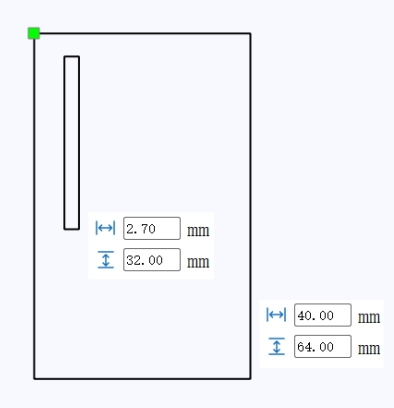
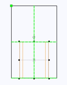
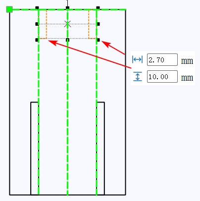
Add two smaller 2.7 mm by 10 mm mortises at the top of the boom support board for the boom connection. Then add a 10 mm by 2.7 mm tenon at the bottom so the support board can be inserted into the base chassis top plate.
The winch drum passes through the motor fixing plates and is driven by the motor. In this lesson, the drum uses cross-axle parts made from interlocking laser-cut boards.
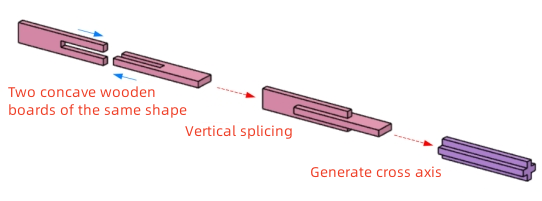
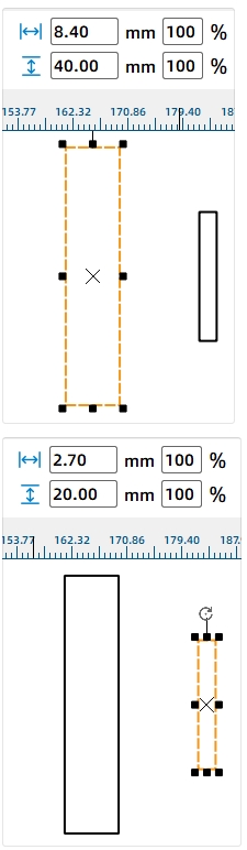
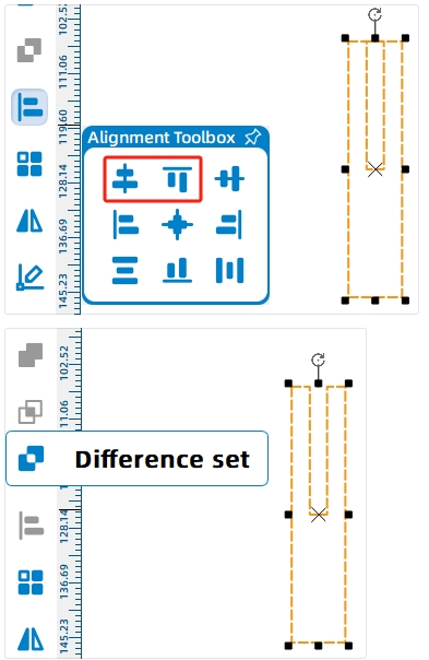
Draw one cross-axle piece as an 8.4 mm by 40 mm rectangle. Add a 2.7 mm by 20 mm slot, align it at the top center, and use Difference to create the interlocking shape. Since the winch drum and boom need four cross shafts in total, create eight matching cross-axle pieces with Rectangular Array.
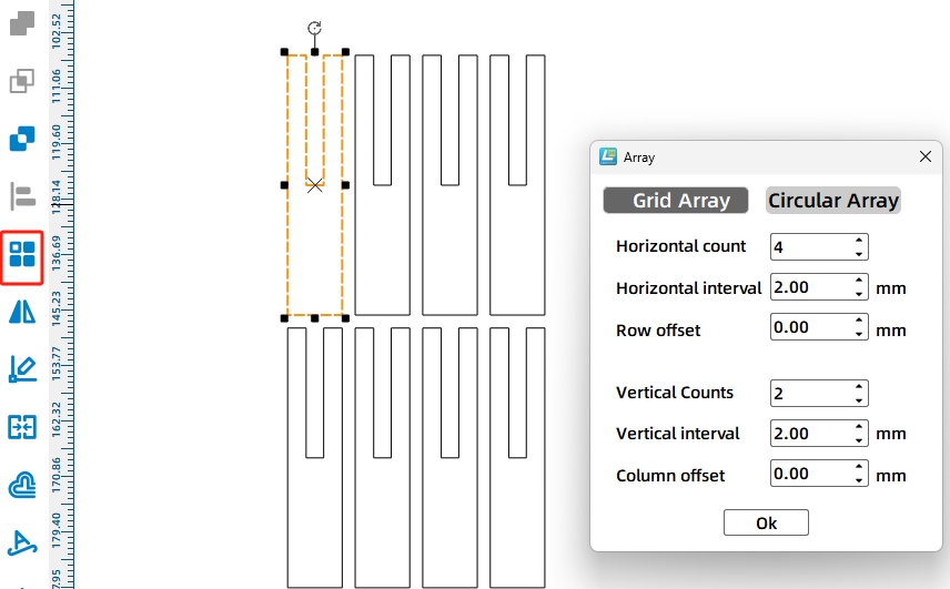
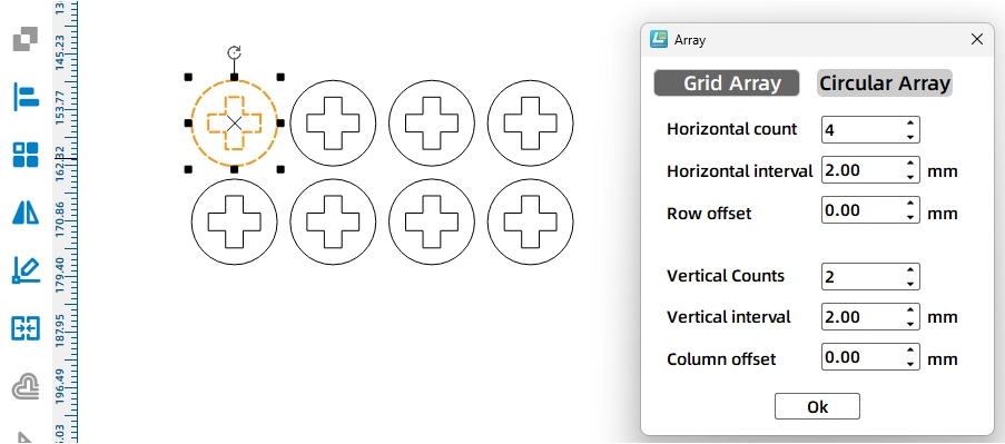
To keep the shafts from loosening or shifting during rotation, draw circular axle sleeves. Create a 15 mm circle and place a cross-shaped shaft hole at its center. Use Rectangular Array to create eight sleeves.

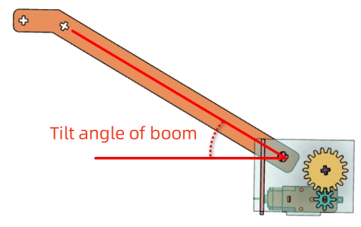
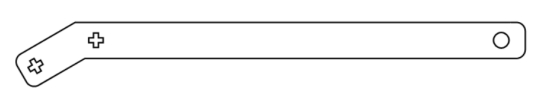
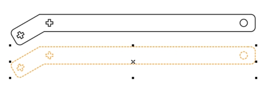
The boom is made from two identical side plates. It includes a long arm and a short arm. The long arm reaches outward, while the short arm connects to the lifting support structure and guides the cable direction.
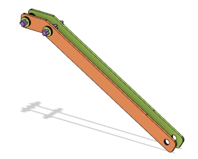
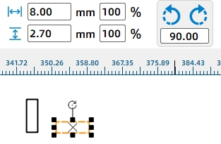
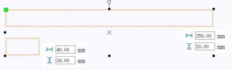
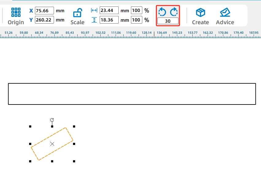
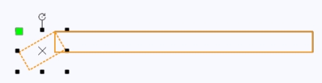
Draw a 250 mm by 20 mm rectangle for the long arm and a 40 mm by 20 mm rectangle for the short arm. Rotate the short arm by -30 degrees, align it with the long arm, and merge the two rectangles with Union.
Add two cross-shaped axle holes at the front end of the boom to redirect the cable. Add an 8 mm circular hole at the rear end to simplify installation. Duplicate the completed boom side plate so the boom has two matching sides.
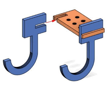
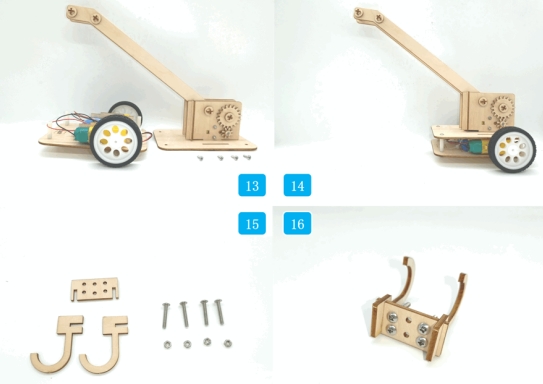
The hook is shaped like a capital J and is assembled from two curved hook plates and one rectangular upper plate. The rectangular plate includes two center holes for the lifting rope and four additional holes where screws and nuts can be added to increase hook weight.
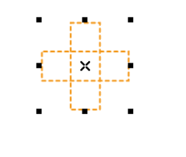
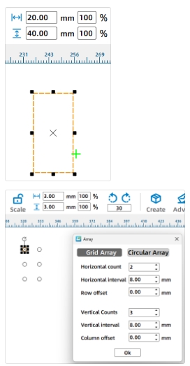
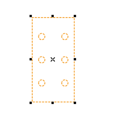
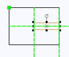
Draw the upper hook plate as a 20 mm by 40 mm rectangle. Add six 3 mm circular holes with Rectangular Array, using 2 horizontal holes, 3 vertical holes, and 8 mm spacing. Center-align the grouped holes inside the rectangle.
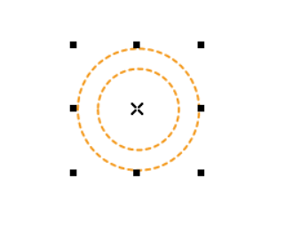
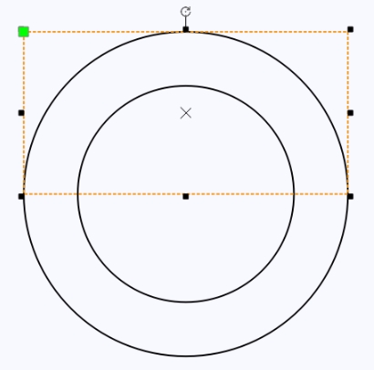
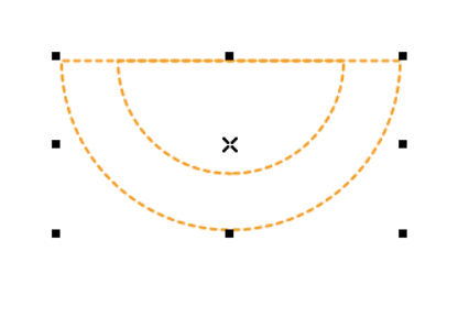
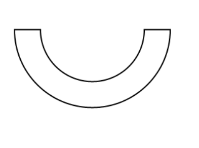
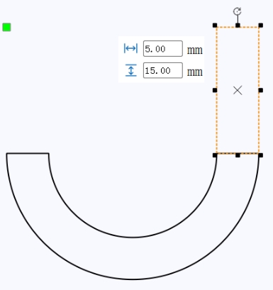
To draw the J-shaped hook plate, create two concentric circles with diameters of 30 mm and 20 mm. Use a rectangle and Difference operations to create a half-ring shape. Add a 5 mm by 15 mm rectangle to form the hook tip.
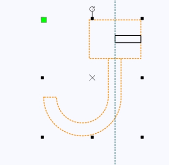
Add the connecting section between the hook and upper plate. Draw a 20 mm by 15 mm rectangle and a 10 mm by 2.7 mm tenon rectangle, align them, and merge the hook shape with the connecting shape using Union. Duplicate the finished J-shaped hook plate.

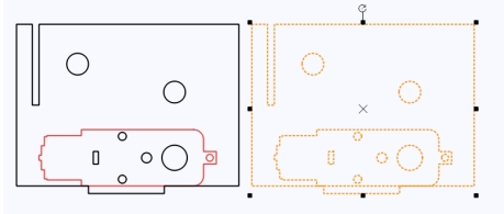
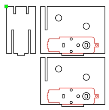
After all crane parts are complete, move each final production part into a clean layout, delete extra construction graphics, assign the correct layers, and prepare the file for laser processing.
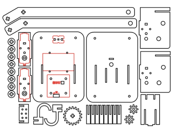
The crane project uses two main laser processes. Red-layer objects are used for outlining or surface marking, while black-layer objects are cut through the basswood plywood.
Outlining: Double-click the red block in the processing area. Select Basswood Plywood as the material, choose Outlining, and set the cutting depth to 0.10.
Cutting: Double-click the black block in the processing area. Select Basswood Plywood as the material, choose Cutting, and set the cutting depth to 3.00.
Turn on the laser cutting machine and laser switch. When the Start Fabrication button becomes ready, upload the drawing to the laser cutting machine and start cutting from the machine panel.
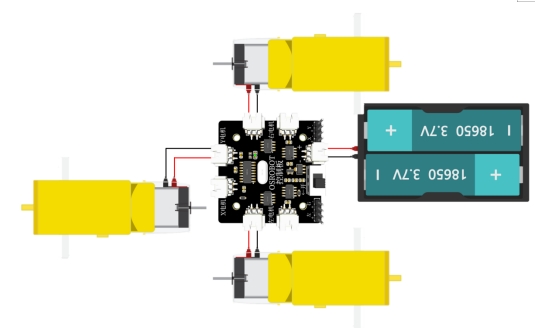
Connect the circuit according to the wiring diagram. The crane lifting motor connects to the receiver so the winch can reel the cable in or out by remote control.
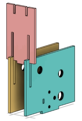
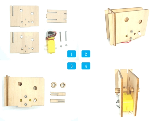
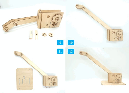
Start with the two motor mounting plates, the boom support plate, motor, screws, and nuts. Install the two motor mounting plates on both sides of the motor, then insert the boom support plate into the front grooves from top to bottom.
Assemble the cross shaft, pass it through the round holes on the motor mounting plates, and add cross-hole sleeves between the plates. Install the large gear on the cross shaft and the small gear on the motor shaft, then secure both ends with circular sleeves.
Next, assemble the boom. The front cross shaft should pass through the boom side plates and include two cross-hole sleeves to help prevent misalignment. Use another cross shaft to connect the boom to the rotating support structure.
Install the lifting structure onto the upper deck panel of the vehicle body. Insert the tenons at the bottom of the rotating support structure into the mortises on the vehicle’s upper deck, and pass the motor wires through the deck holes.
Connect the crane motor wires to the X Motor connector on the receiver board. Then assemble the vehicle upper panel with the chassis and secure it with screws.
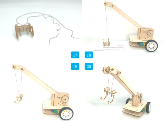
Assemble the hook by connecting the two J-shaped hook plates with the rectangular upper plate through mortise-and-tenon joints. Add screws and nuts to the outer holes to increase hook weight when needed. Use the two center holes for the lifting rope.
Thread the lifting rope through the two center holes of the hook. Route one end through the gap between the two circular sleeves at the front of the boom and clamp it with the sleeves. Route the other end upward through the second front boom shaft and connect it to the circular sleeve on the winch shaft.
Check whether the small gear and large gear mesh smoothly before lifting any object.
Confirm that the cross shafts rotate without loosening, shifting, or rubbing heavily against the support plates.
Test whether the winch can reel the lifting rope in and out without tangling.
Observe whether the boom stays stable when the hook moves up and down.
Adjust hook weight, rope length, and sleeve spacing if the hook drifts too much during lifting.
After design, laser processing, wiring, and assembly, students complete a remote-control crane. The project gives students practical experience with gear transmission, fixed-pulley ideas, winch operation, boom structure, hook counterweight, cable routing, and laser-cut mechanical assembly.
During testing, the source lesson notes that the hook may drift when it is not attached to an object, even after extra weight is added. As an extension challenge, students can design a better hook-stabilizing method, adjust the counterweight, add a guide, change the rope path, or redesign the boom tip to reduce swinging.
Students can also compare different gear ratios, boom angles, hook weights, and cable routing methods to see how each change affects lifting speed, stability, and control.
This project is suitable for classroom laser cutters that support cutting and marking of sheet materials for robotics and mechanism projects. For schools, makerspaces, and beginner STEAM labs, projects like remote-control cranes, winch models, gear transmission systems, and laser-cut robot attachments can be completed with a classroom laser cutter such as the Thunder Laser Bolt Series.
Teachers can choose the machine and material setup based on classroom space, project size, material thickness, electronic components, moving-part clearance, and learning goals. The same LaserMaker workflow can also be adapted for other CO2 laser machines when students move on to more advanced lifting mechanisms or competition-style robot tasks.
Talk To Our Experts Now!
Please leave your contact information so that we can serve you better.
TAKE THE NEXT STEP WITH THUNDER LASER

 Stable & Consistent MachinesUnlimited ApplicationRobust After-sales SupportFactory Direct Supply


