


Remote-Control Paddlewheel Boat Laser Cutting Project with LaserMaker
 24-07-25
WHAT ARE YOU LOOKING FOR?
Search Across Products, Blog Posts, Support Content, And Resources.

Remote-Control Paddlewheel Boat Laser Cutting Project with LaserMaker
24-07-25

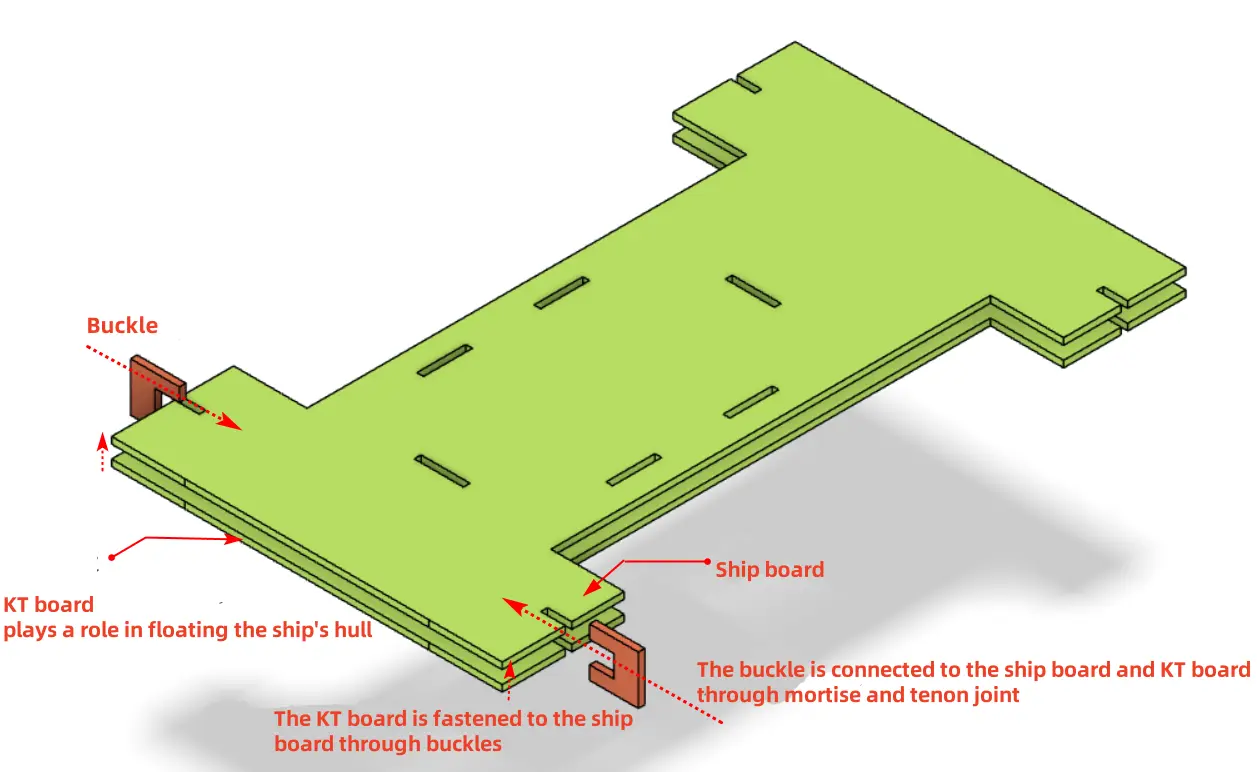
In this STEAM robotics and mechanism project, students design and build a remote-control paddlewheel boat using LaserMaker. The lesson connects paddlewheel propulsion, vertical gear transmission, floating structure design, mortise-and-tenon assembly, laser-cut paddlewheels, remote-control components, wiring, and hands-on testing.
This project helps students understand how a boat can move without a propeller. Students explore how a TT motor can drive a vertical gear set, how the gear set turns a paddlewheel shaft, and how paddle blades push water to move the model forward.
| Item | Details |
|---|---|
| Project | Remote-control paddlewheel boat / water cruise model |
| Software | LaserMaker |
| Main Skills | Modular Gear tool, Rectangular Box creation, Rectangle Tool, Ellipse Tool, Difference, Union, alignment guides, Circular Array, Rectangular Array, mortise-and-tenon design, laser cutting, wiring, and assembly |
| Suggested Materials | Basswood board, KT board, bamboo stick, 2.4G remote-control components, TT motor, 18650 batteries, screws, nuts, and nylon standoffs |
| Classroom Fit | Robotics and mechanism projects, gear transmission, water-themed engineering activities, maker education, laser cutting, remote-control structures, and buoyancy discussions |
Students will design a paddlewheel boat with a cabin, hull, paddlewheel system, gear transmission, shaft sleeves, and floating support. They will create the parts in LaserMaker, laser cut the structure, assemble the mechanical and electronic components, and test whether the paddlewheels can move the model on water.
For teachers: Use this project to connect gear transmission, waterproofing considerations, buoyancy, propulsion, alignment, and digital fabrication.
For students: Use the activity to build a small powered boat while learning how rotating paddle blades can push water and create motion.
For makerspaces: Use it as an advanced remote-control mechanism project that combines laser-cut structures, gears, paddlewheels, wiring, and water testing.
Analyze how a paddlewheel boat differs from a propeller-driven boat.
Use a vertical gear transmission to keep the motor farther from the water surface while still driving the paddlewheel shaft.
Create a cabin, hull, deck, paddlewheel disks, paddle blades, clips, and shaft sleeves in LaserMaker.
Apply Union, Difference, alignment guides, gear generation, circular arrays, and rectangular arrays to build accurate laser-cut parts.
Assemble the mechanical structure, connect the remote-control circuit, and test the paddlewheel boat carefully on water.
Design thinking: Turn a real paddlewheel boat into a classroom-scale model with a cabin, hull, paddlewheels, and floating support.
Computational thinking: Use gear parameters, centerline alignment, shaft-hole positions, array settings, and part dimensions to create a precise digital model.
Engineering thinking: Consider motor height, gear meshing, shaft alignment, paddlewheel clearance, buoyancy, friction, joint fit, and stable movement on water.
Students should test the boat only under teacher or lab supervisor guidance. Keep electronic components as dry as possible, check wiring before launch, and remove the model from water immediately if the structure becomes unstable or the electronics are exposed.
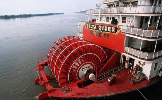
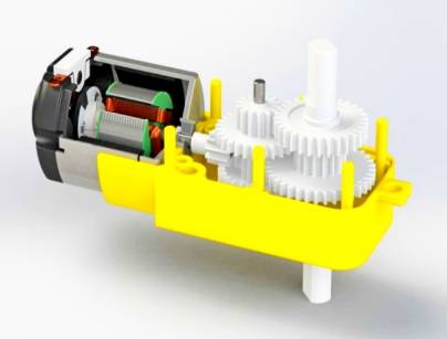
A paddlewheel boat moves differently from a conventional propeller-driven boat. Instead of using a propeller, it has paddlewheel devices with paddle blades on the sides of the hull. When the motor drives the paddlewheels, the blades stir the water and push the boat forward.
In this lesson, students study a real paddlewheel boat and then create a remote-control water cruise model. Because the model operates near water, the design uses a vertical gear transmission to keep the motor farther from the water surface while still transferring motion to the paddlewheel shaft.

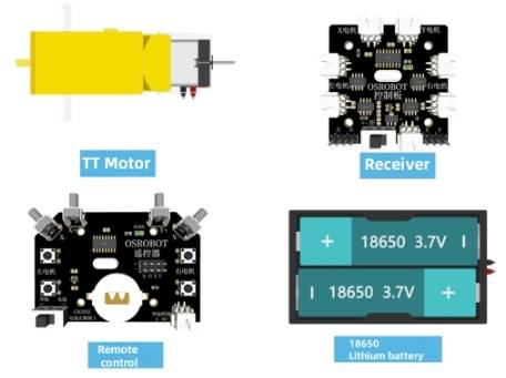
Before modeling the paddlewheel boat, students should identify the remote-control components, structural materials, floating support material, shaft material, and hardware used in the project.
| Number | Name | Quantity |
|---|---|---|
| 1 | 2.4G Remote Control | 1 |
| 2 | 2.4G Receiver | 1 |
| 3 | TT Motor | 1 |
| 4 | 18650 Battery | 2 |
| 5 | 18650 Battery Holder | 1 |
| 6 | Basswood Board, 40 cm × 60 cm × 3 mm | 1 |
| 7 | M3/M4 Screws, Nuts, and Nylon Standoffs | Several |
| 8 | KT Board, 40 cm × 60 cm × 3 mm | 1 |
| 9 | Bamboo Stick, 4 mm diameter, about 200 mm long | 1 |
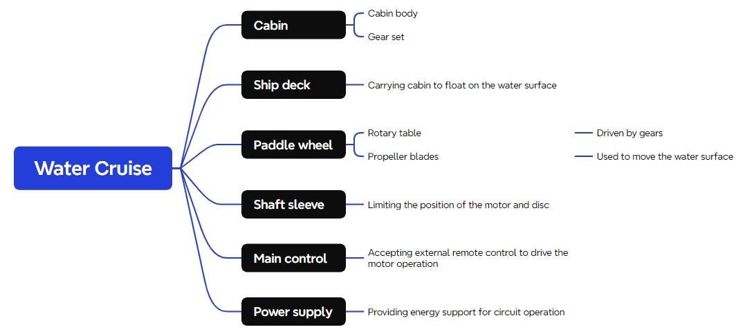
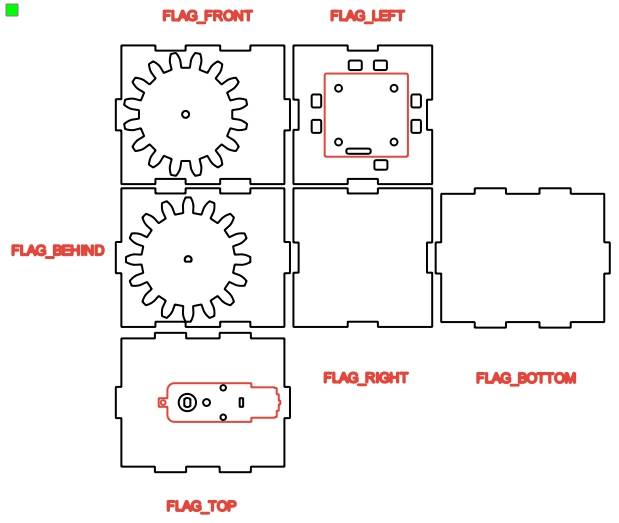
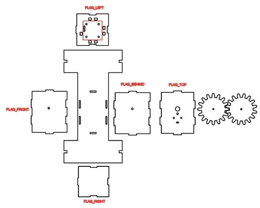
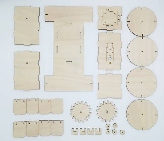
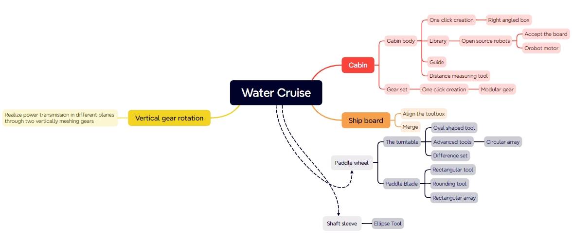
The laser-cut structure is divided into four main groups: the cabin, hull, paddlewheel, and shaft sleeves.
| Part No. | Part Name | Quantity | Function |
|---|---|---|---|
| 1 | Cabin | 1 | Houses the gear assembly, motor, and receiver board |
| 2 | Hull | 1 | Supports the cabin and floats on the water |
| 3 | Paddlewheel | 1 set | Driven by the gear assembly to propel the boat through paddle rotation |
| 4 | Shaft Sleeve | 10 | Limits and positions the gear shaft and paddlewheel shaft |
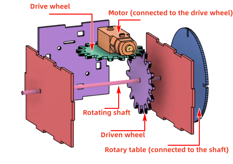
The cabin contains the gear assembly, motor, and receiver board. To avoid a mismatch between the gear system and the cabin dimensions, students should design the gear assembly first, then adjust the cabin around it.
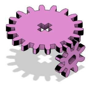
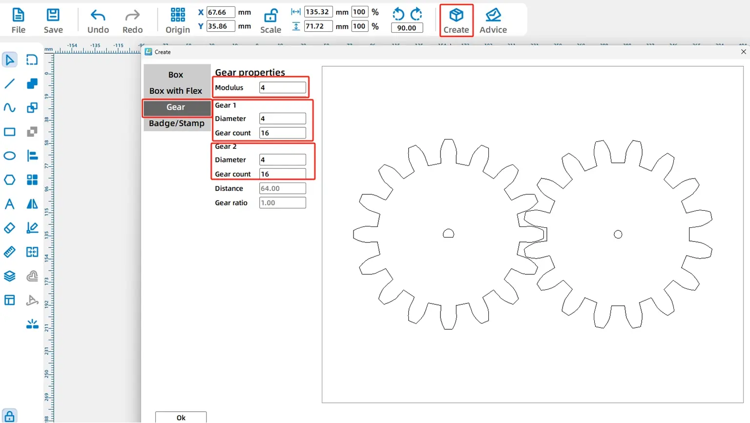
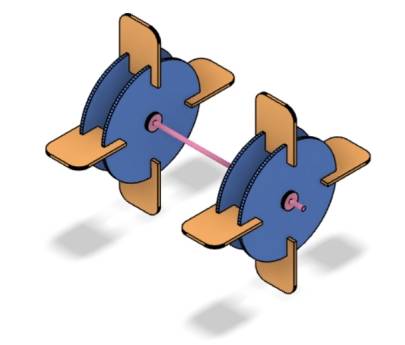
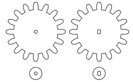
In this model, one gear is mounted on the TT motor shaft as the driver gear. Another gear is mounted on the paddlewheel transmission shaft as the driven gear. The two gears mesh vertically so the motor can transfer motion to the paddlewheel shaft.
Use the Modular Gear tool in LaserMaker. In the source workflow, the module is set to 4, the shaft diameter is set to 4 mm, and the tooth count is set to 16. After confirming the settings, two gears of the same size are generated.
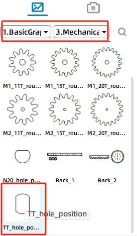
One gear connects to the TT motor, so the default center hole needs to be replaced. Delete the N20 shaft hole in the left gear, then choose the TT Hole graphic from Mechanical Parts and place it at the gear center.
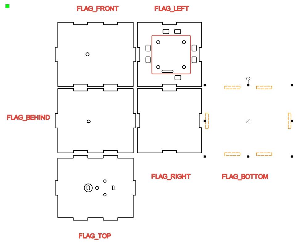
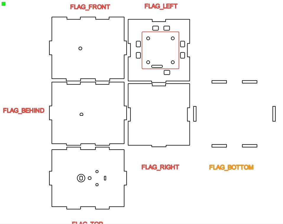
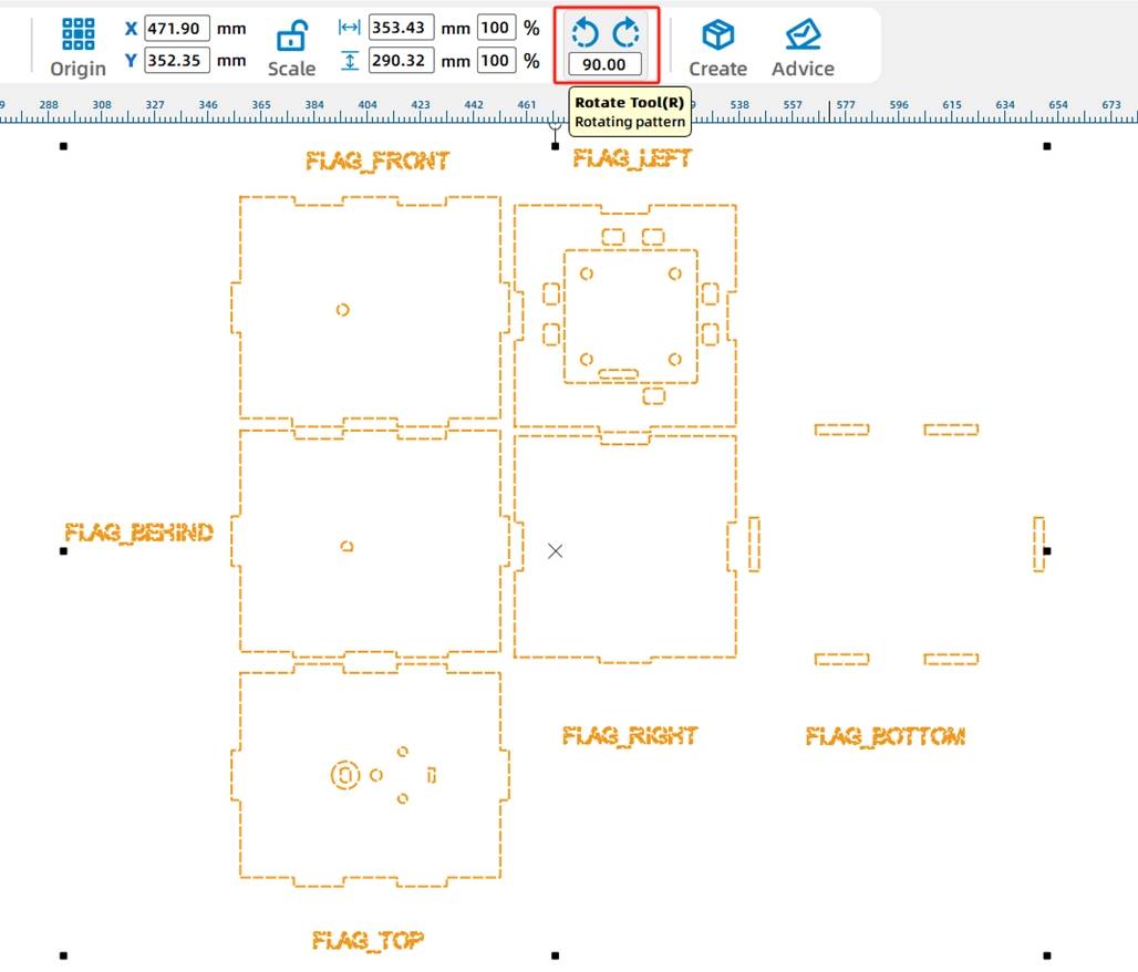
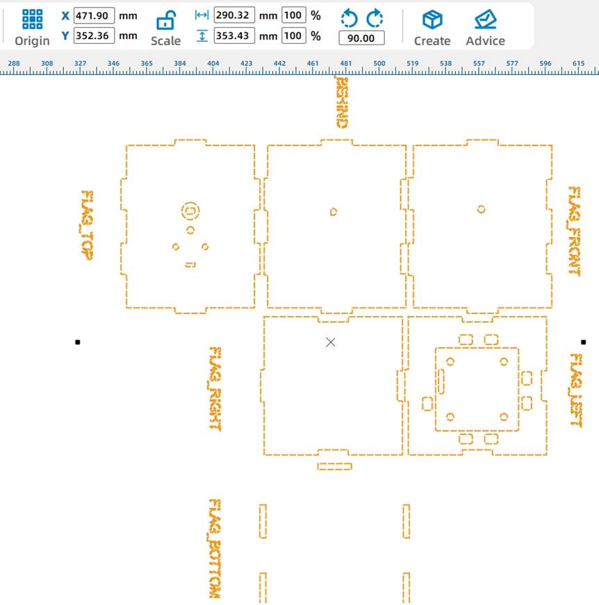
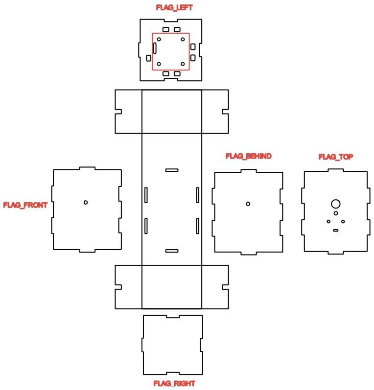
The cabin is a box structure that holds the transmission mechanism and circuit board. Use the Rectangular Box tool in LaserMaker. In the source workflow, the box length, width, and height are set to 100 mm, 80 mm, and 80 mm, and the groove size is set to 20 mm.
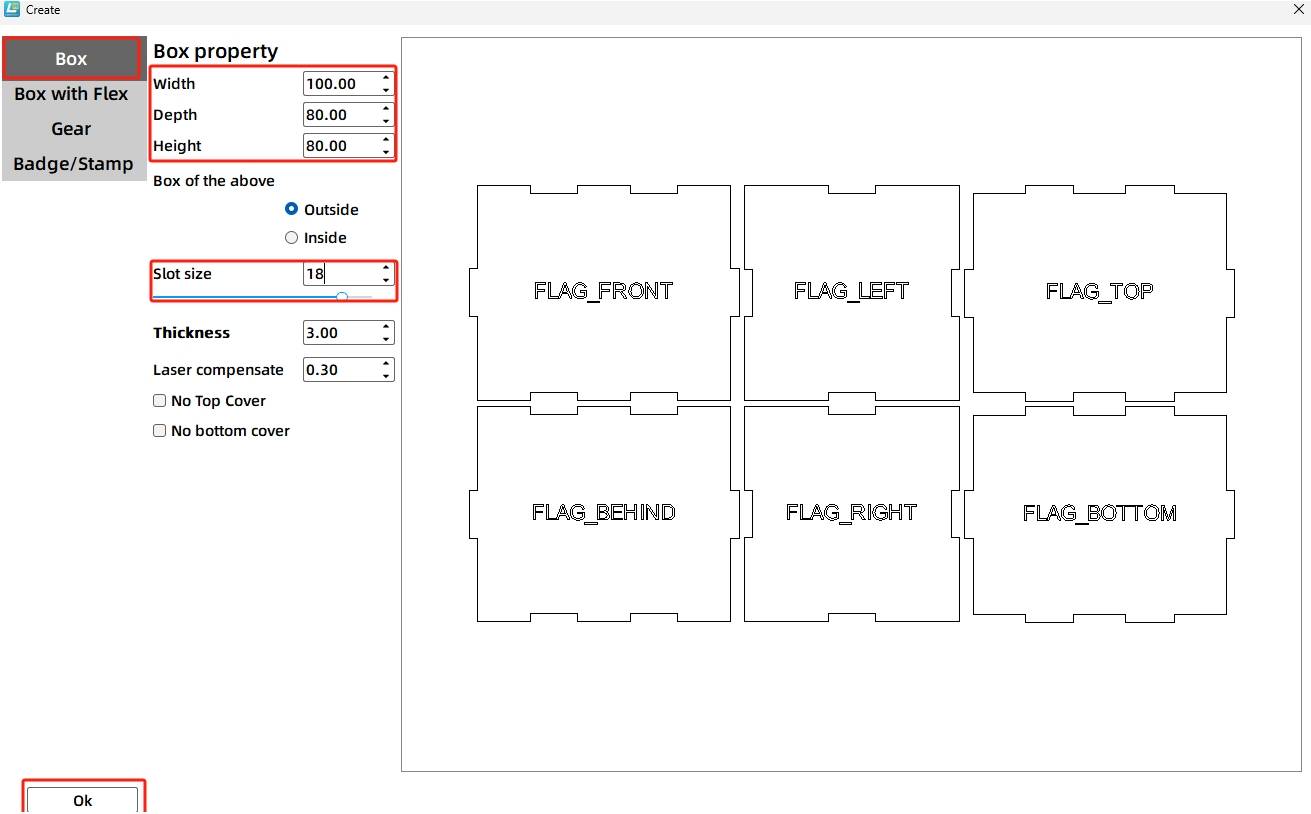
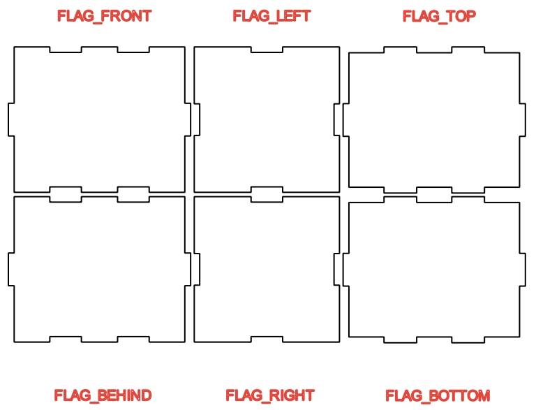
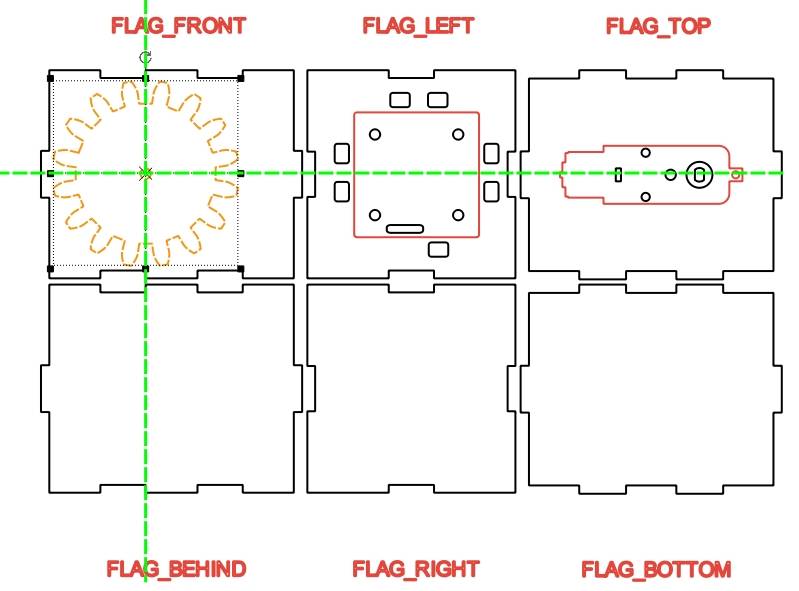
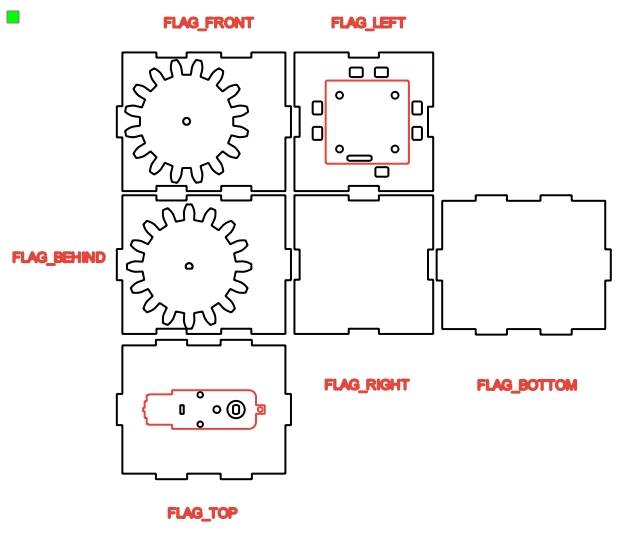
After generating the box, move the prompt labels onto the correct six faces. Then add the 2.0 Control Board graphic to the center of the left panel, and add the TT Motor graphic to the top panel.
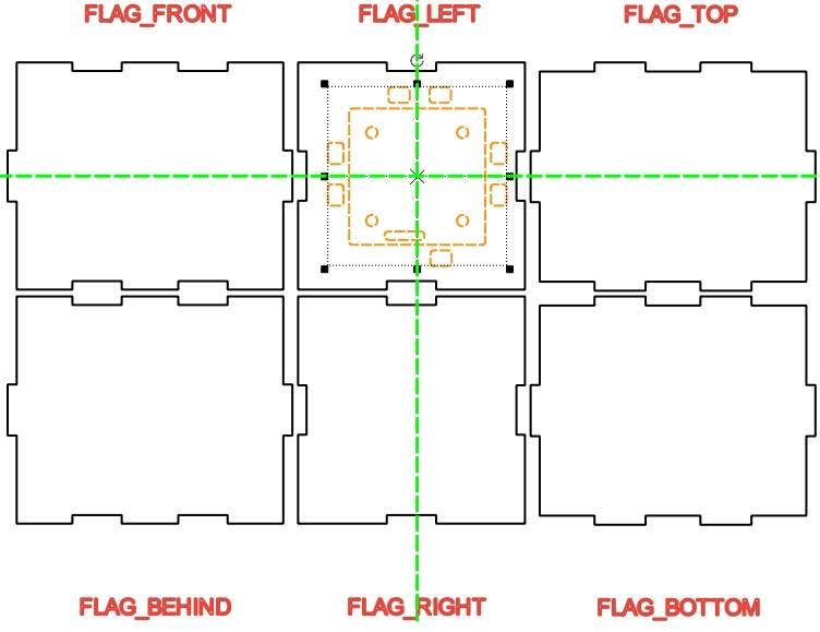
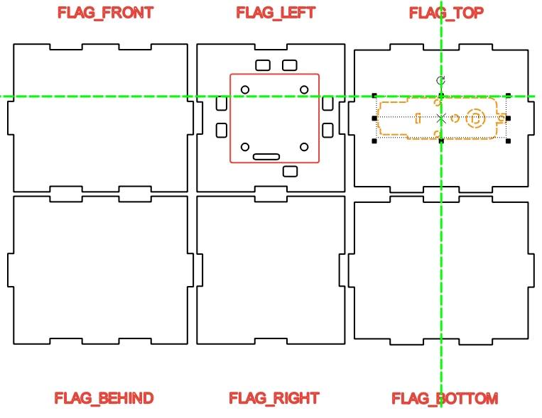
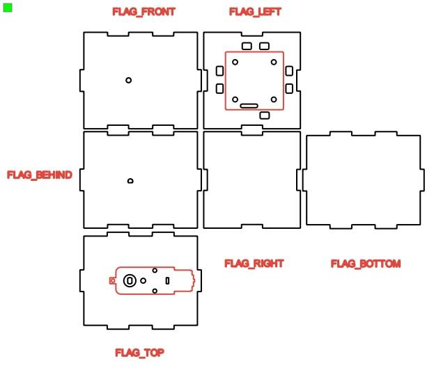
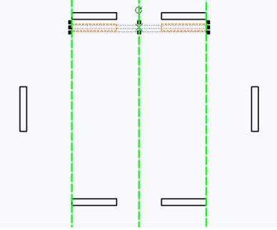
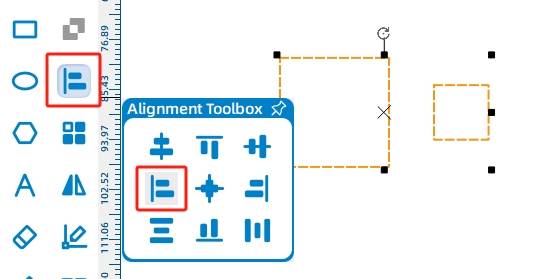
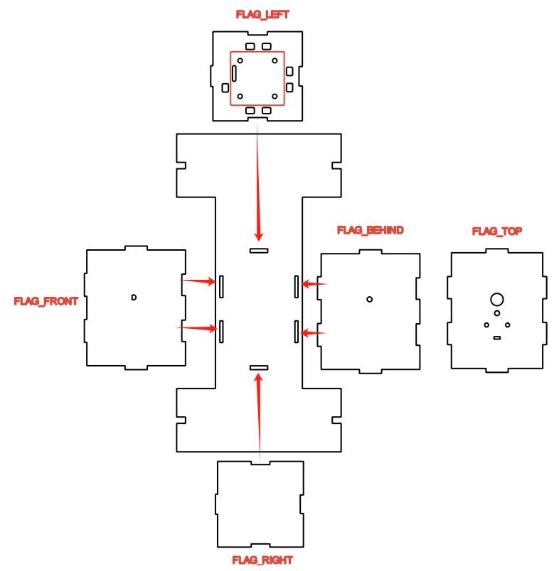
The gear assembly requires accurate alignment. The motor shaft hole, the front panel shaft hole, and the rear panel shaft hole must line up so the gears can mesh correctly and the paddlewheel shaft can pass through the cabin.
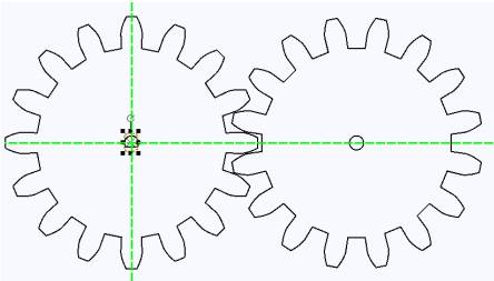
Move the completed gear graphics onto the front and rear panels as alignment references. Adjust their positions so the shaft holes are aligned. The gear outlines can be used as temporary guides, then removed later.
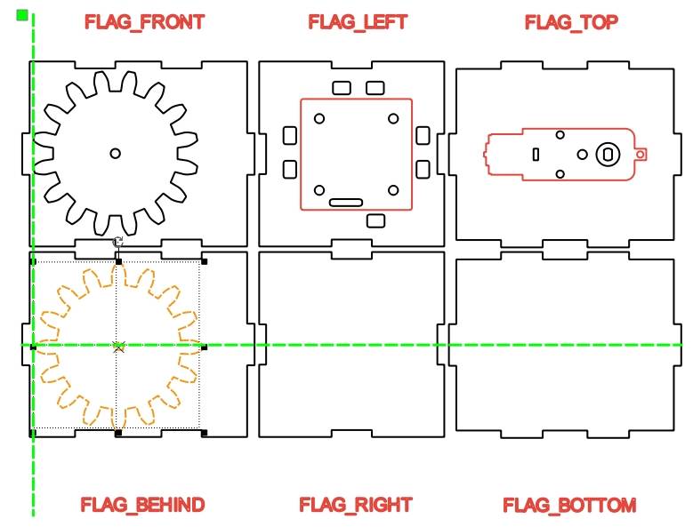
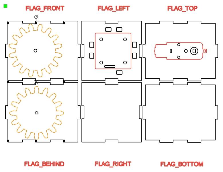
Move and flip the TT motor graphic as needed so its shaft hole aligns with the gear centers. Use vertical guide lines to check that the TT motor shaft hole and the front and rear panel shaft holes are on the same axis.
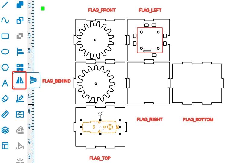
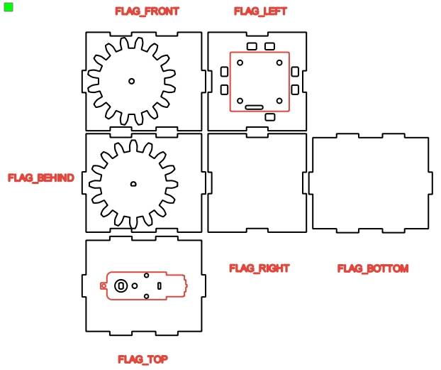
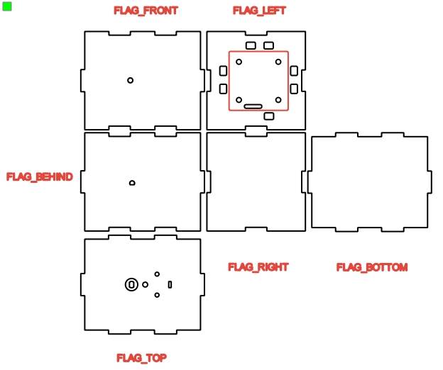
After alignment is complete, delete the temporary gear outlines and keep only the shaft holes. Ungroup the TT motor graphic and delete unnecessary motor outlines while preserving the required mounting and shaft-hole information.
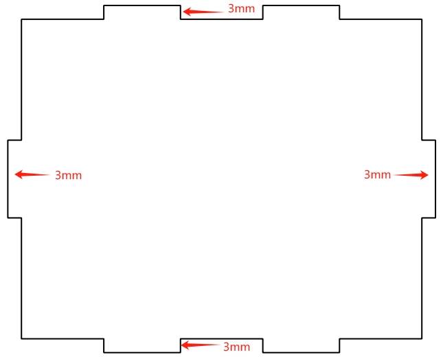
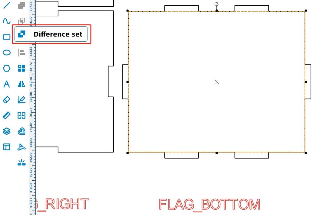
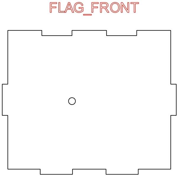
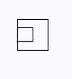
The cabin is installed on the deck with mortise-and-tenon joints. The bottom panel is modified so only the mortise interface remains. In the source workflow, the bottom panel is measured as 106.4 mm by 86.4 mm.
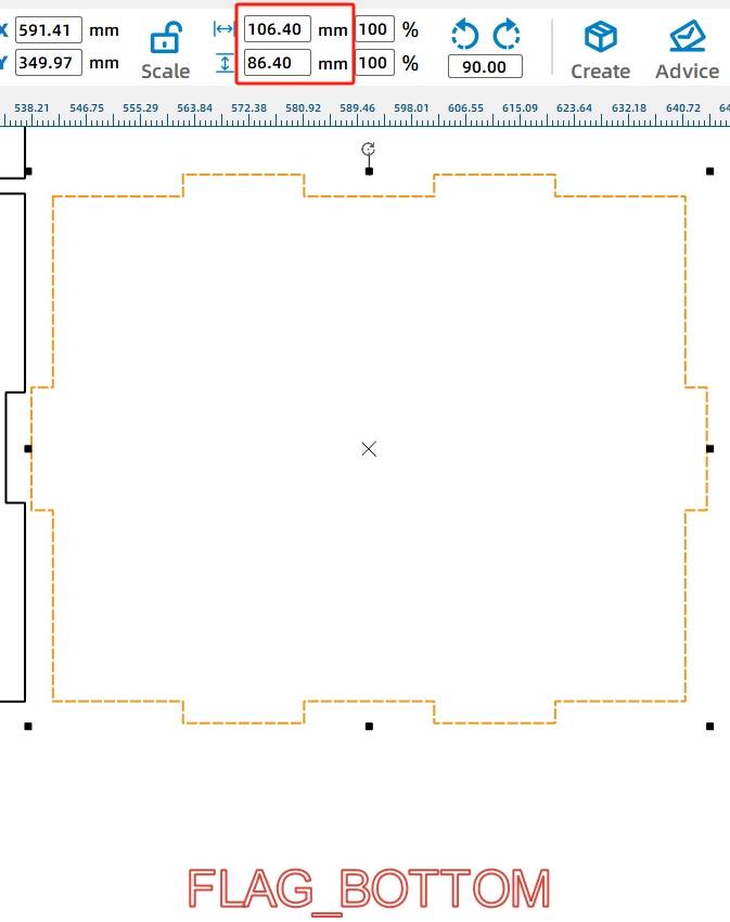
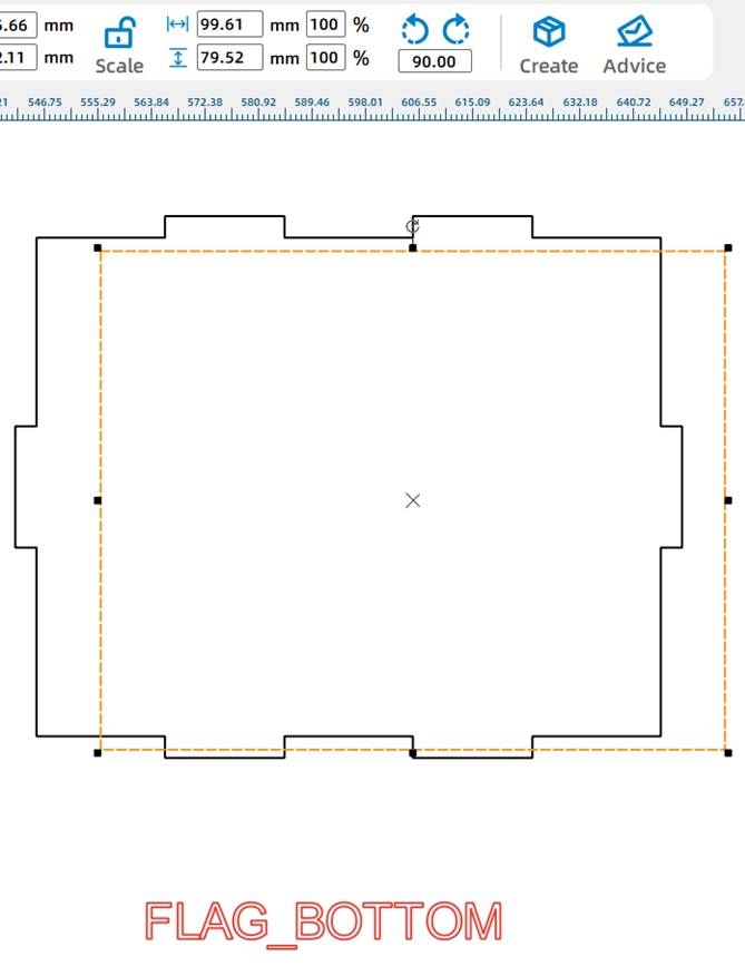
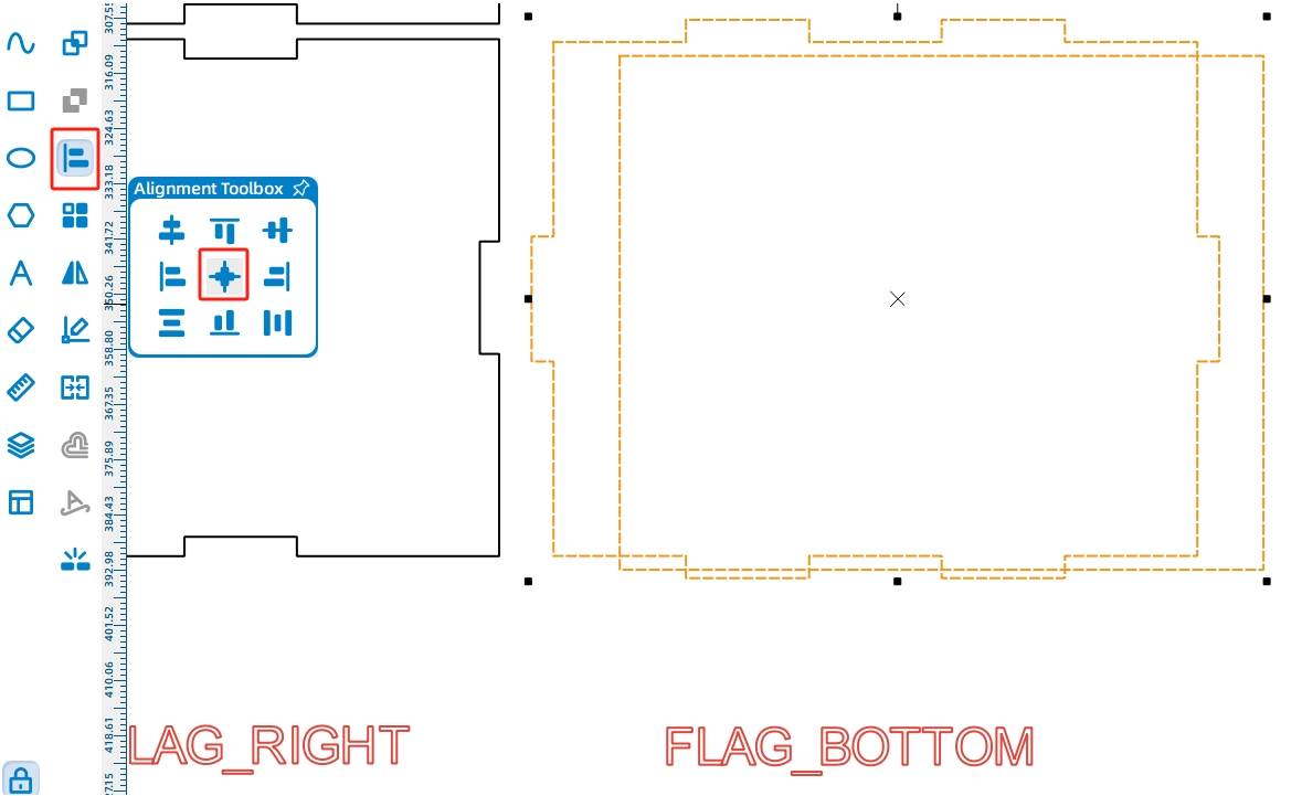
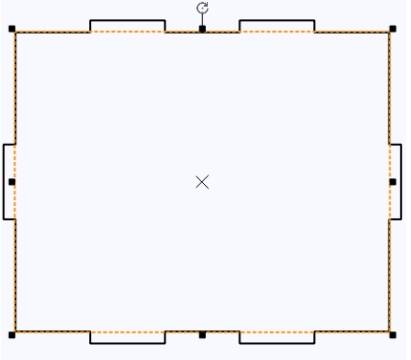
Because the panel has 3 mm tenons on the horizontal and vertical sides, subtracting 6 mm from the width and height gives the internal rectangle size. Draw a rectangle with a width of 99.61 mm and a height of 79.52 mm, align it to the center of the bottom panel, and use Difference to create the mortise structure.
For a tighter fit, the matching tenons can be adjusted manually. The source workflow notes that for a 20 mm by 3 mm mortise, a 20.6 mm by 3 mm tenon can help improve the fit when laser compensation is considered.
Fit Tip: When students design mortise-and-tenon features manually, they should test the fit on scrap material first. Laser kerf and material behavior can affect how tight or loose the final joint feels.
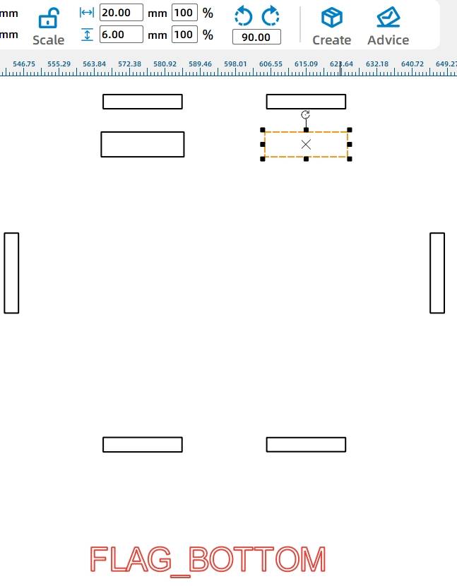
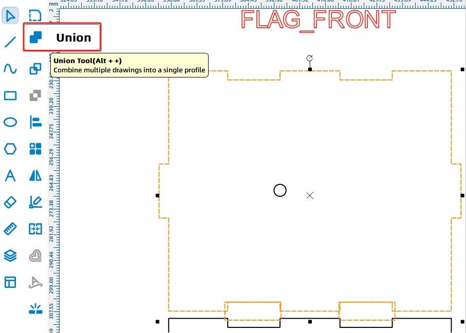
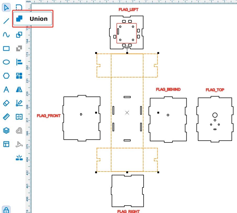
Copy two horizontal mortises, resize them to 20.6 mm wide and 6 mm high, align them with the panel edge, and use Union to turn the original mortise area into tenons. Repeat the process for the rear, left, right, and lower panel joints.
-.jpg)

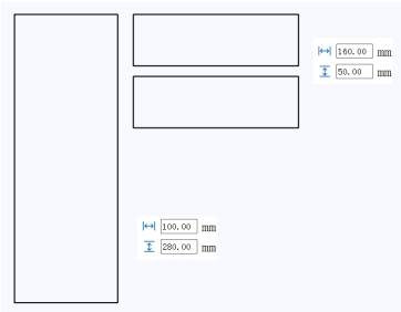
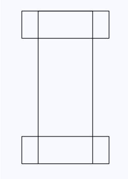
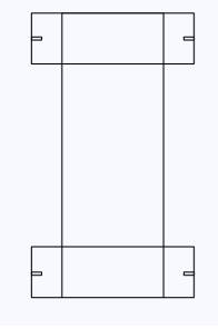
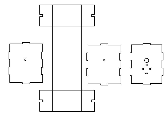
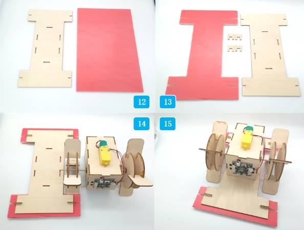
The gunwale supports the cabin above and connects to the KT board below so the boat can float. Because the paddlewheels are placed on both sides, the gunwale is designed as an “I” shape with wider ends and a narrower middle.
Use the Rectangle Tool to draw one large rectangle that is 100 mm wide and 280 mm high, then draw two smaller rectangles that are 160 mm wide and 50 mm high. Align the smaller rectangles at the top and bottom of the larger rectangle.
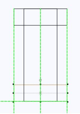
To attach the KT board without drilling through it with screws, the design uses a clip system. Matching mortises are placed in the gunwale and KT board, then U-shaped clips connect them together.
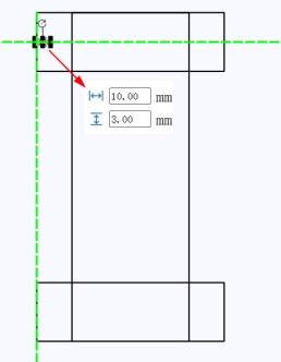
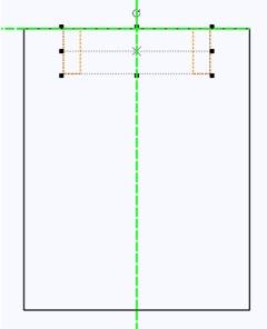
Draw four 10 mm by 3 mm mortise rectangles on the I-shaped gunwale. Use symmetrical placement and guide lines to keep the holes aligned, then use Difference to create the mortises.
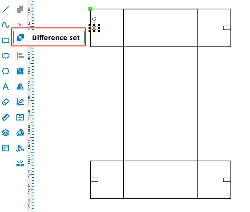
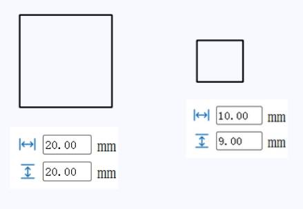
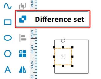
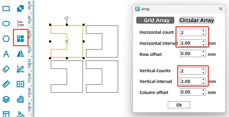
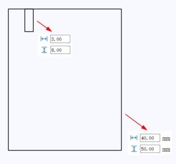
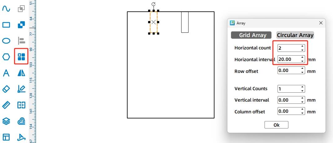
Next, draw the U-shaped clips. Start with a 20 mm by 20 mm rectangle and place a 10 mm by 9 mm rectangle on the left side. Align the rectangles, then use Difference to create the clip shape. Use Rectangular Array to generate four identical clips.
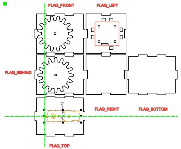
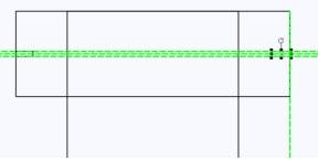
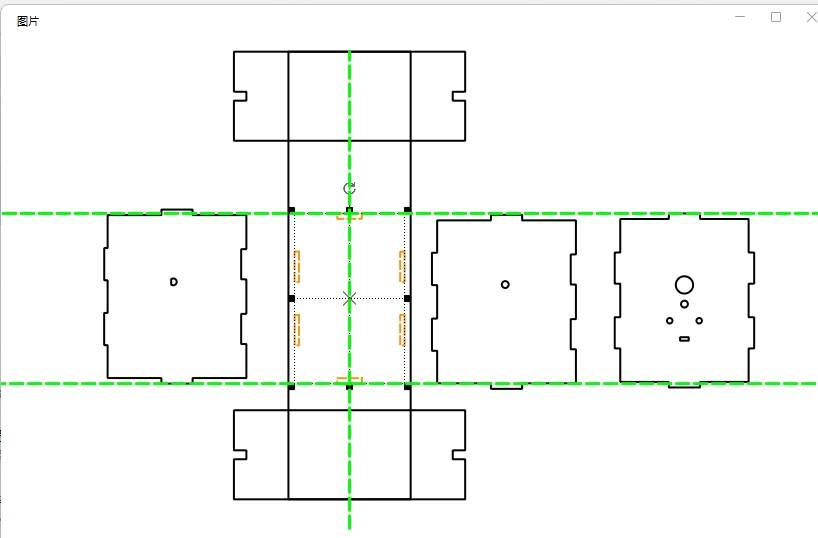
Use guide lines to find the center of the boat. Rotate the cabin graphic 90 degrees and place it near the deck so the cabin tenons, deck mortises, and paddlewheel shaft holes can be aligned around the centerline.
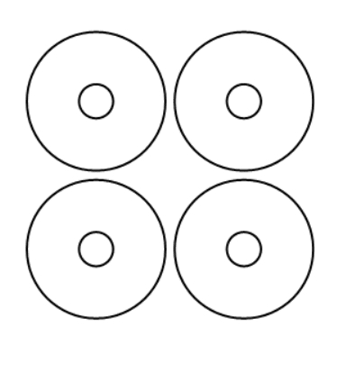
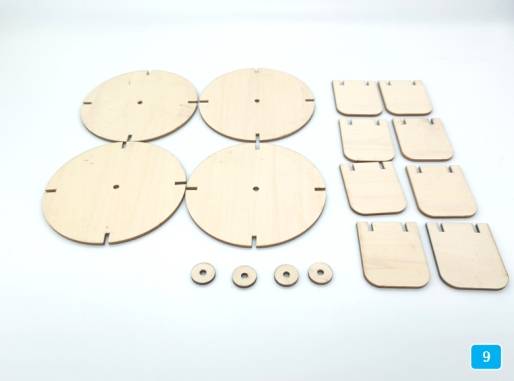
The paddlewheel is the propulsion device of the model. Each side of the boat has a paddlewheel. To make the structure stronger, each paddlewheel uses two rotating disks and four paddle blades connected with mortise-and-tenon joints.
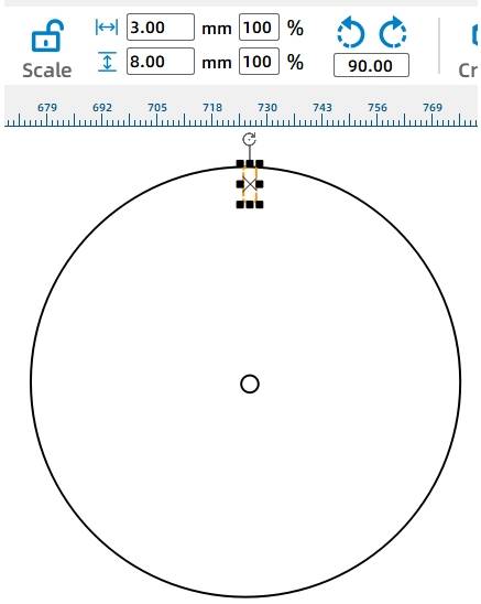
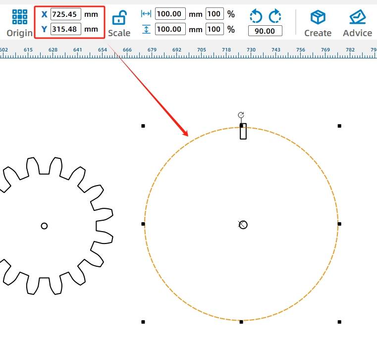
Place the two gears near one side of the deck to check shaft alignment. Then draw a 100 mm circle with a 4 mm center hole for the rotating disk, and align it with the cabin and deck shaft centerline.
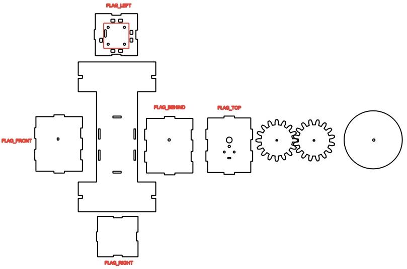
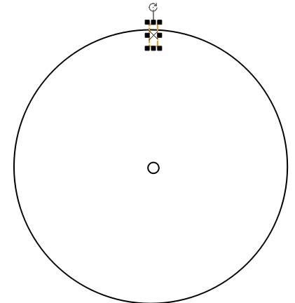
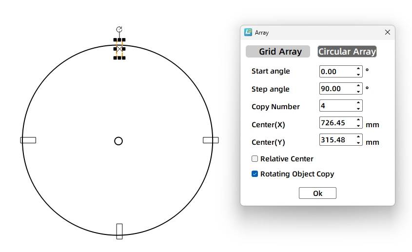
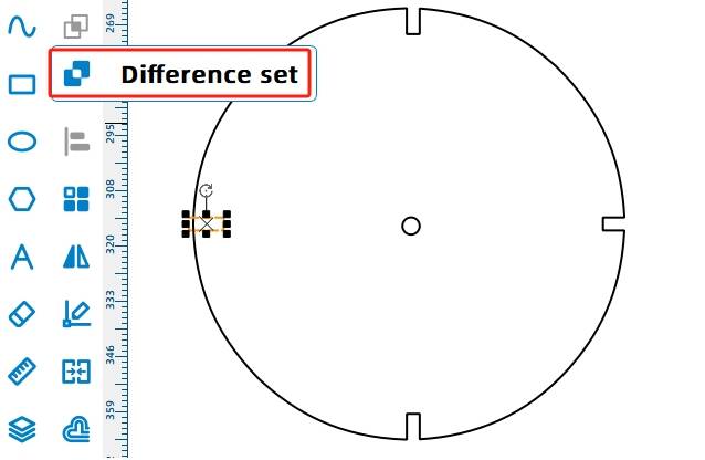
Draw a 3 mm by 8 mm rectangle above the circle to create one paddle-blade mortise. Adjust it so it intersects the disk outline, then use Circular Array to create four mortises around the disk with a 90-degree step angle. Use Difference to cut the mortises.
The paddle blades are attached orthogonally to the rotating disks. When the TT motor drives the disks, the blades stir the water and help move the boat forward or backward.
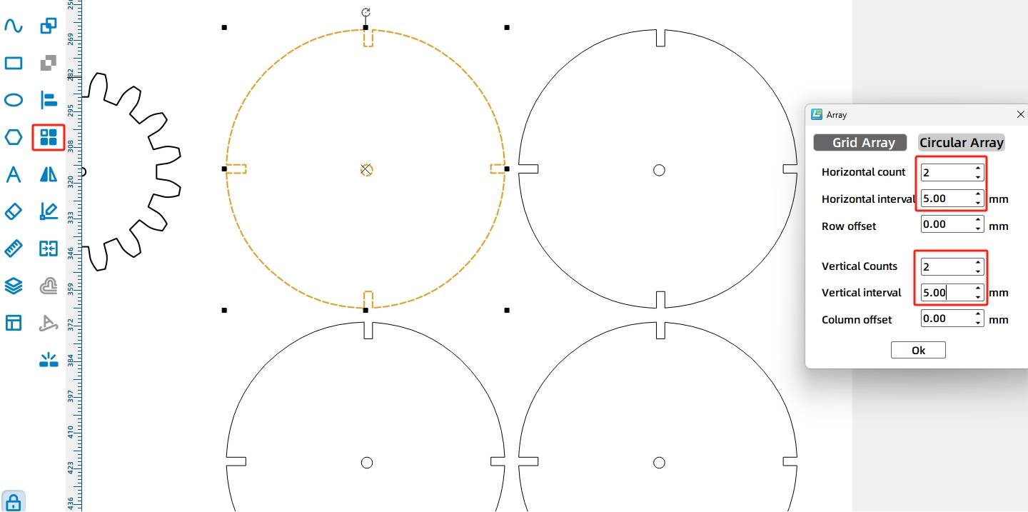
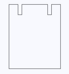
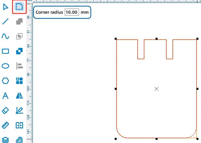
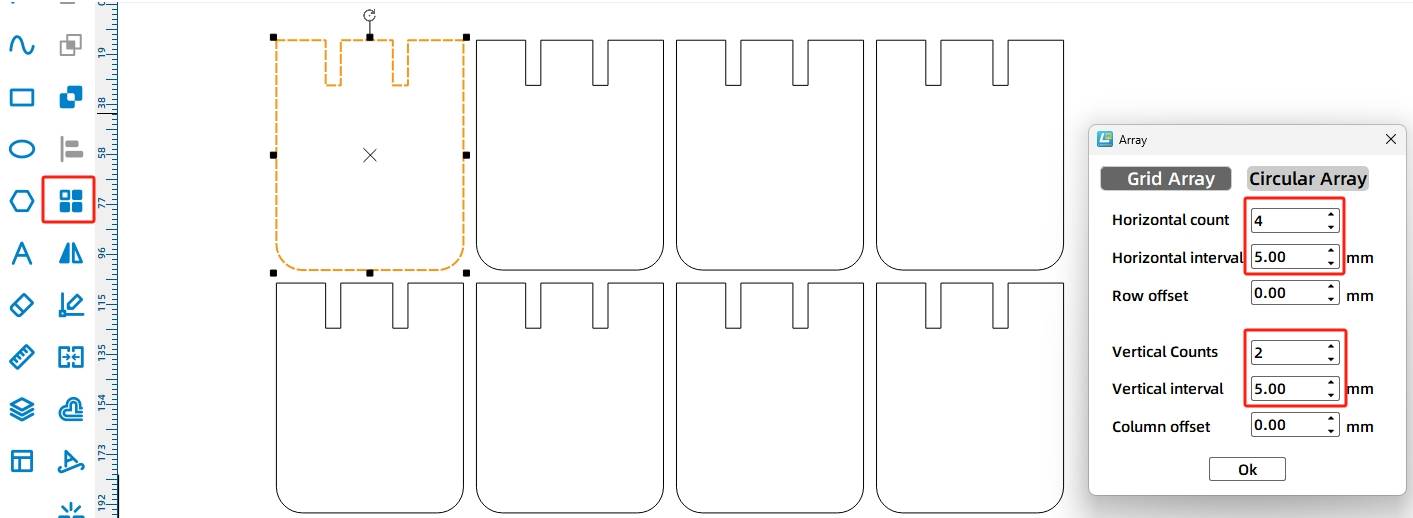
Draw one paddle blade as a 40 mm by 50 mm rectangle. Add two 3 mm by 8 mm mortise rectangles, use Difference to create the slots, and round the two lower corners with a 10 mm radius. Then use Rectangular Array to create eight paddle blades.
Shaft sleeves help keep the rotating disks and gears in position. For the paddlewheel shaft, the source workflow uses an outer diameter of 15 mm and an inner diameter of 3.7 mm for a tighter fit around the 4 mm bamboo stick.
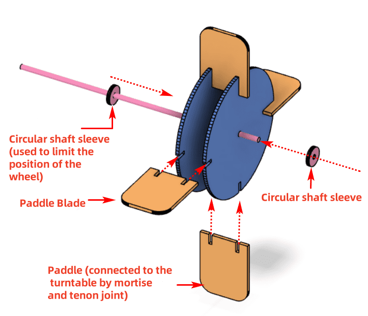
Draw ring-shaped shaft sleeves for the paddlewheel, and draw additional shaft sleeves for the two gears. The gear-related sleeves keep the same 15 mm outer diameter, while the center holes match either the TT motor shaft hole or the 3.7 mm round shaft hole.
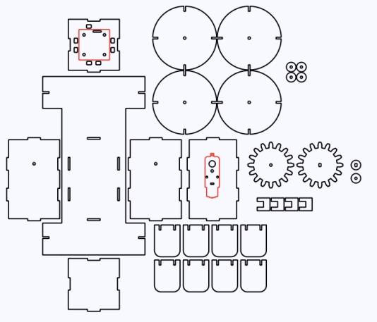
After completing the drawings, check the speed and power settings for tracing and cutting. Use Simulate Fabrication to review the process sequence before sending the file to the laser cutter.
After the water cruise model is assembled, connect the circuit according to the wiring diagram. The remote control, receiver, battery holder, batteries, and TT motor work together to power the paddlewheel system.
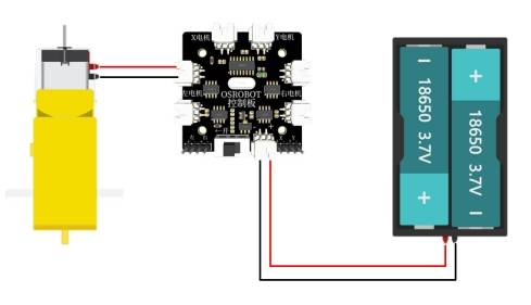
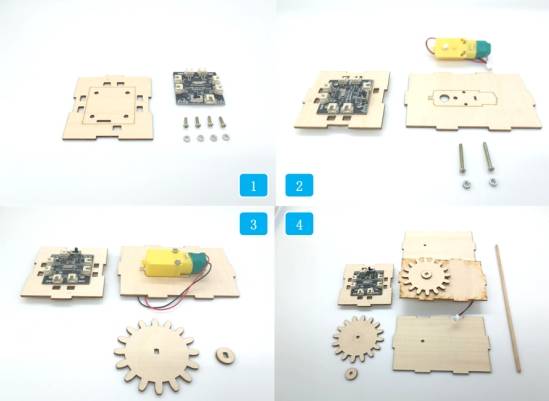
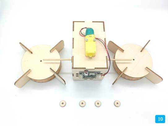
Start by mounting the receiver board and TT motor onto the hull with M3 screws and nuts. Install the TT-compatible gear and matching shaft sleeve onto the TT motor shaft.
Next, install the round-hole gear, gear sleeve, 4 mm bamboo stick, and the two perforated cabin side panels. Pass the stick through the panel, gear, gear sleeve, and opposite panel in sequence.
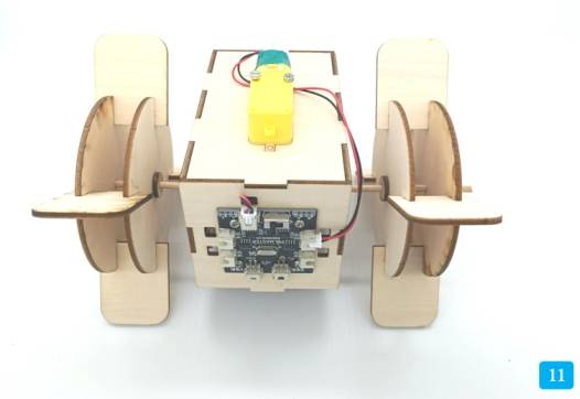
Connect the panel with the receiver board and TT motor to the shaft structure. Add the paddlewheel shaft sleeves and the remaining hull panel. Pass the battery through the preset panel hole from inside the hull, then connect the TT motor and power wires to the receiver board interfaces.
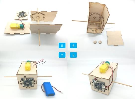
Assemble the paddlewheels by inserting four paddle blades into the notches of two rotating disks. Repeat the process for the second paddlewheel. Place the paddlewheel clips and paddlewheels onto the exposed bamboo stick on both sides of the hull. Adjust the shaft sleeves to optimize paddlewheel alignment.
Finally, prepare the deck parts and KT board. Place the deck on the KT board and mark the notch positions and side openings. Cut away the excess KT board material, then use the deck clips to connect the deck and KT board. Attach the deck assembly to the completed hull section with the mortise-and-tenon joints.
Check whether the vertical gear transmission turns smoothly before launching the model.
Confirm that the paddlewheels do not rub against the deck, hull, or shaft sleeves.
Test whether the KT board provides enough buoyancy for the assembled structure.
Inspect the battery, receiver, and motor positions to reduce water exposure during testing.
Observe whether the paddle blades push water effectively and whether the boat moves in the intended direction.
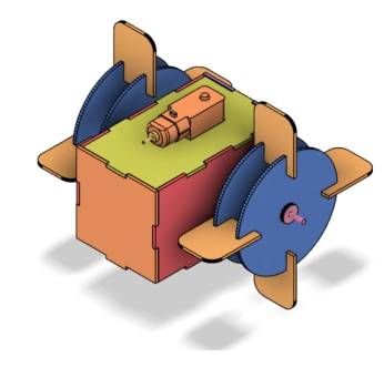
After design, laser cutting, wiring, assembly, and water testing, students complete a remote-control paddlewheel boat model. The project gives students hands-on experience with vertical gear transmission, paddlewheel propulsion, buoyancy support, shaft alignment, mortise-and-tenon construction, and digital fabrication.
In this project, the paddlewheel boat uses paddlewheels on both sides and a motor-driven transmission system. As an extension challenge, students can test a different propulsion layout, such as using a single paddlewheel at the stern of the boat.
Students can also compare how paddle size, paddle number, shaft alignment, gear fit, and floating material affect the movement and stability of the model.
This project is suitable for classroom laser cutters that support cutting of sheet materials for small robotics and mechanism projects. For schools, makerspaces, and beginner STEAM labs, projects like paddlewheel boats, gear transmission models, remote-control structures, and water-themed engineering activities can be completed with a classroom laser cutter such as the Thunder Laser Bolt Series.
Teachers can choose the machine and material setup based on classroom space, project size, material thickness, electronic components, and testing environment. The same LaserMaker workflow can also be adapted for other CO2 laser machines when students move on to larger boats or more advanced mechanism projects.
Talk To Our Experts Now!
Please leave your contact information so that we can serve you better.
TAKE THE NEXT STEP WITH THUNDER LASER

 Stable & Consistent MachinesUnlimited ApplicationRobust After-sales SupportFactory Direct Supply


