


Remote-Control Lucky Roulette Laser Cutting Project with LaserMaker
 24-07-09
WHAT ARE YOU LOOKING FOR?
Search Across Products, Blog Posts, Support Content, And Resources.

Remote-Control Lucky Roulette Laser Cutting Project with LaserMaker
24-07-09

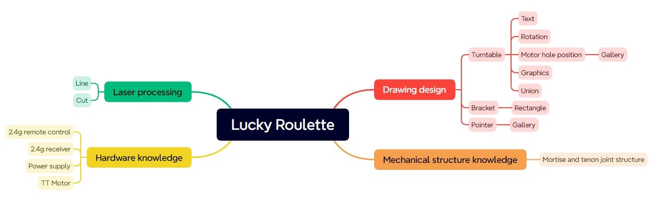
In this STEAM robotics and mechanism project, students design and build a remote-control lucky roulette using LaserMaker. The lesson connects laser-cut structure design, motor mounting, pointer rotation, text tracing, mortise-and-tenon supports, wireless control components, wiring, and final assembly.
This project helps students move beyond a static laser-cut object and build a simple powered game device. Students learn how a rotating disk, pointer, TT motor, receiver, batteries, and laser-cut stand work together to create an interactive roulette game.
| Item | Details |
|---|---|
| Project | Remote-control lucky roulette |
| Software | LaserMaker |
| Main Skills | Ellipse Tool, Rectangle Tool, Rounded Corner Tool, Text Tool, Library Panel graphics, TT Motor mounting, Union Tool, grouping, rotation, tracing, cutting, wiring, and assembly |
| Suggested Material | Basswood panel, 40 cm × 60 cm × 3 mm |
| Classroom Fit | Robotics and mechanism projects, game design, maker education, laser cutting, motorized structures, and beginner remote-control activities |
Students will design a lucky roulette with a rotating disk, pointer, motor mount, and support stands. They will create the laser-cut parts in LaserMaker, set tracing and cutting parameters, assemble the structure, wire the control components, and test whether the pointer spins successfully.
For teachers: Use this project to connect digital drawing, mechanical structure, motor control, wiring, and game-based learning.
For students: Use the activity to design a working roulette game that can randomly select a game item, prize, or classroom challenge.
For makerspaces: Use it as an introductory powered maker project that combines laser cutting with basic electronic control.
Draw a circular roulette disk, pointer, and stand parts with LaserMaker drawing tools.
Use the Library Panel to place TT Motor and mechanical hole graphics accurately.
Use Union, grouping, rotation, grid, guide lines, and alignment tools to prepare the model.
Set tracing and cutting processes for text, motor holes, pointer parts, and structural outlines.
Assemble a powered roulette with a TT motor, 2.4G remote control, receiver, batteries, and support hardware.
Design thinking: Turn a familiar game object into a laser-cut interactive device with clear text, a stable stand, and a readable pointer.
Computational thinking: Use dimensions, alignment guides, rotation angles, layer colors, and processing settings to organize the drawing.
Engineering thinking: Consider motor placement, pointer length, disk stability, mortise-and-tenon fit, wiring layout, and reliable spinning behavior.
Students should create school-appropriate roulette options, avoid unsafe game prompts, and test powered components only under teacher or lab supervisor guidance. Battery-powered projects should be assembled carefully and checked before use.
A lucky roulette is a game device with a disk divided into different sections. When the pointer spins and stops, it points to one section and helps the player choose a prize, activity, or challenge.
In this project, students design a powered roulette for a game-selection scenario. The roulette uses a TT motor and remote-control components so the pointer can spin automatically instead of being turned by hand.

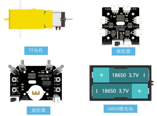
Before drawing the structure, students should review the required materials and understand how each component supports the final powered roulette.
| Number | Name | Quantity |
|---|---|---|
| 1 | 2.4G Remote Control | 1 |
| 2 | 2.4G Receiver | 1 |
| 3 | TT Motor | 1 |
| 4 | 18650 Battery | 2 |
| 5 | 18650 Battery Box | 1 |
| 6 | Basswood Panel, 40 cm × 60 cm × 3 mm | 1 |
| 7 | M3/M4 Screws, Nuts, and Nylon Standoffs | Several |
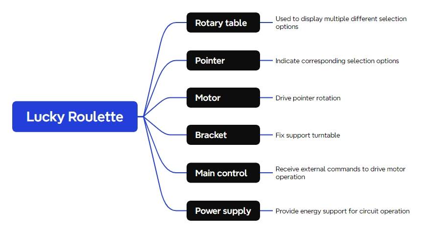
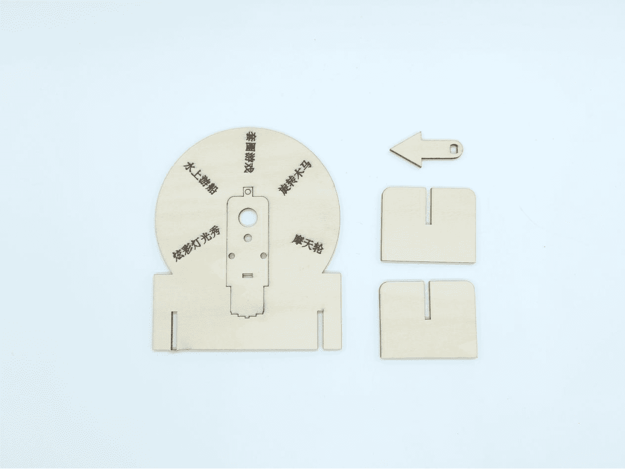
The laser-cut structure is organized into three main parts: the rotating disk, the pointer, and the stand.
| Part Number | Part Name | Quantity | Function |
|---|---|---|---|
| 1 | Rotating Disk | 1 | Display selection text and fix the motor |
| 2 | Pointer | 1 | Point to the selected section |
| 3 | Stand | 2 | Support and fix the rotating disk |
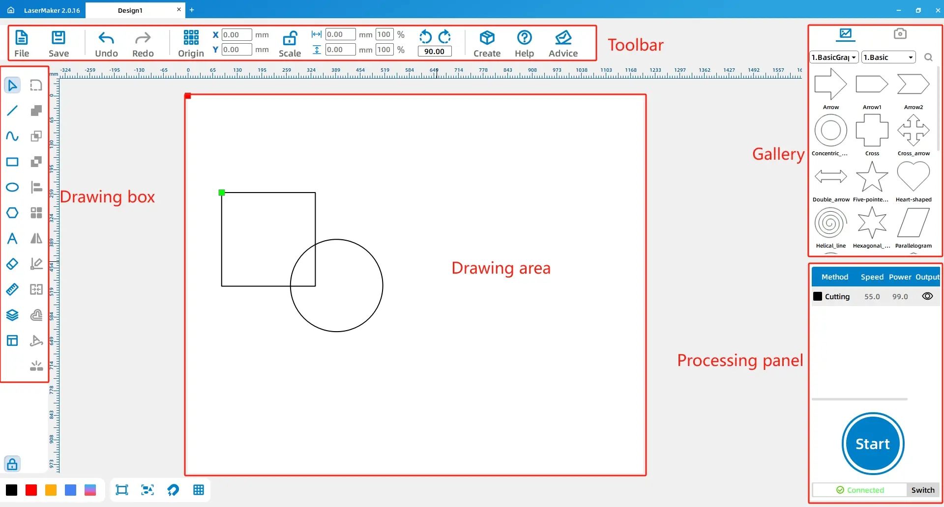
Open LaserMaker and review the main work areas, including the toolbar, drawing box, library panel, drawing area, layer palette, and processing panel. These areas will be used throughout the project.
Select the Ellipse Tool and draw a 100 mm diameter circle. The roulette disk is based on a circular shape, which makes the selection wheel easy to understand and visually familiar.
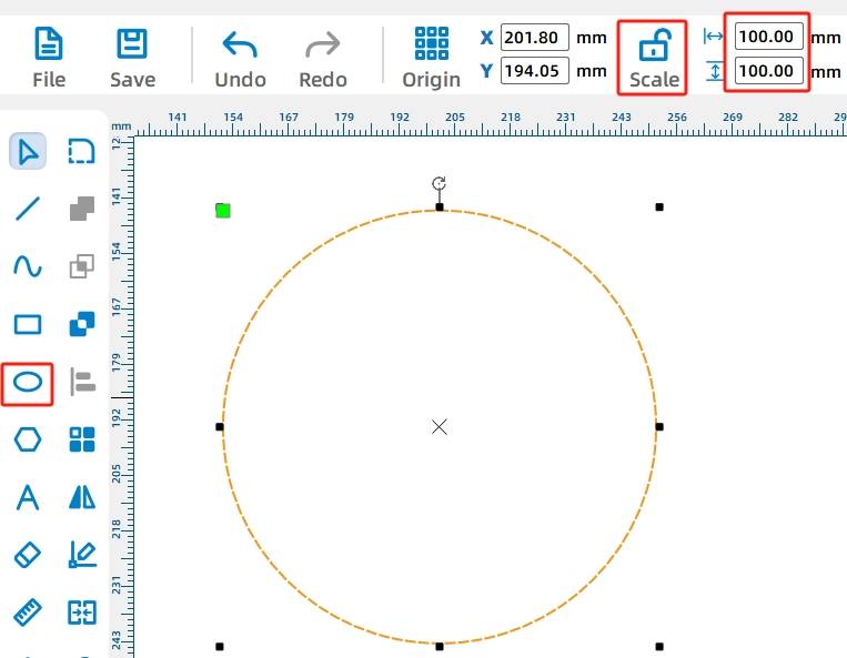
Tool Tip: When using Rectangle, Ellipse, or Polygon tools, holding Ctrl while drawing can help create a square, circle, or regular polygon with a locked 1:1 aspect ratio.
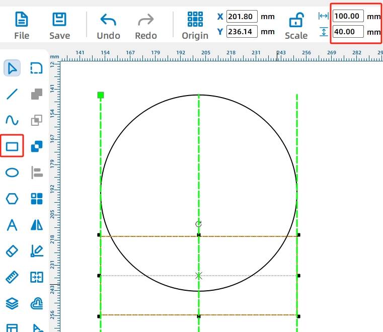
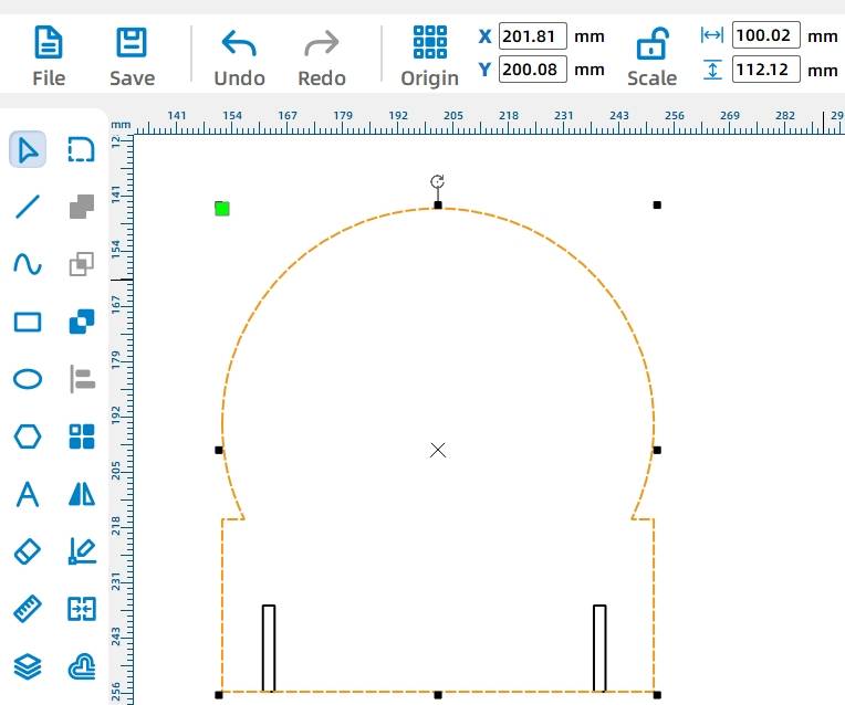
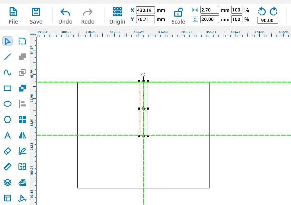
Use the Rectangle Tool to draw a 100 mm by 40 mm rectangle and place it directly below the circle. Use the alignment guides to position the rectangle accurately.
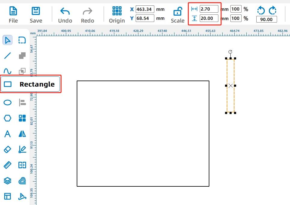
Draw two 2.7 mm by 20 mm rectangles below the larger rectangle. These will become mortise slots for connecting the stands. The source lesson uses 2.7 mm instead of 3 mm to account for laser cutting compensation with basswood.
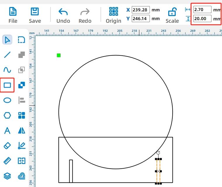
Knowledge Card: A mortise-and-tenon joint connects parts using a protruding tenon and a matching recessed mortise. In this project, the stand parts insert into the disk structure to help it stay upright.
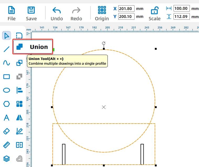
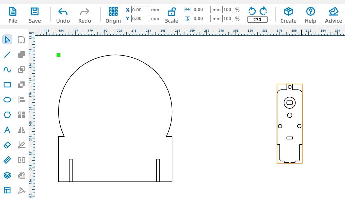
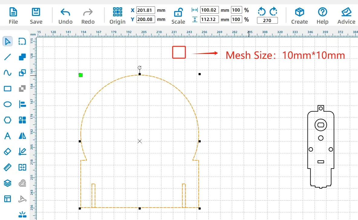
Select the circle and rectangle, then use the Union Tool to merge them into one disk shape. This creates a single continuous outline for the main roulette body.
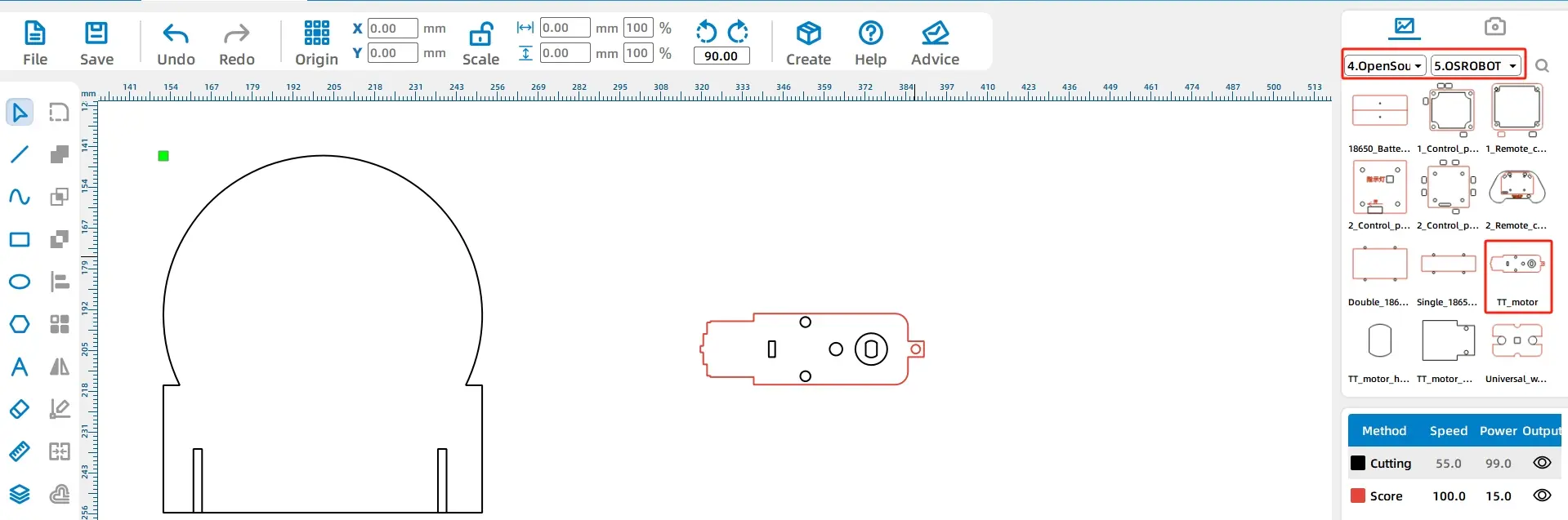
Open the Library Panel, choose Open-source Robot Hardware, select the TT Motor graphic, and drag it onto the drawing area. The source lesson notes that red graphics are used for engraving or tracing marks, while black graphics are used for cutting.
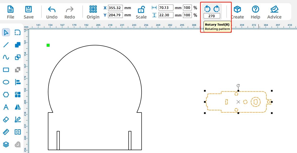
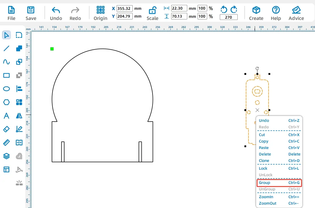
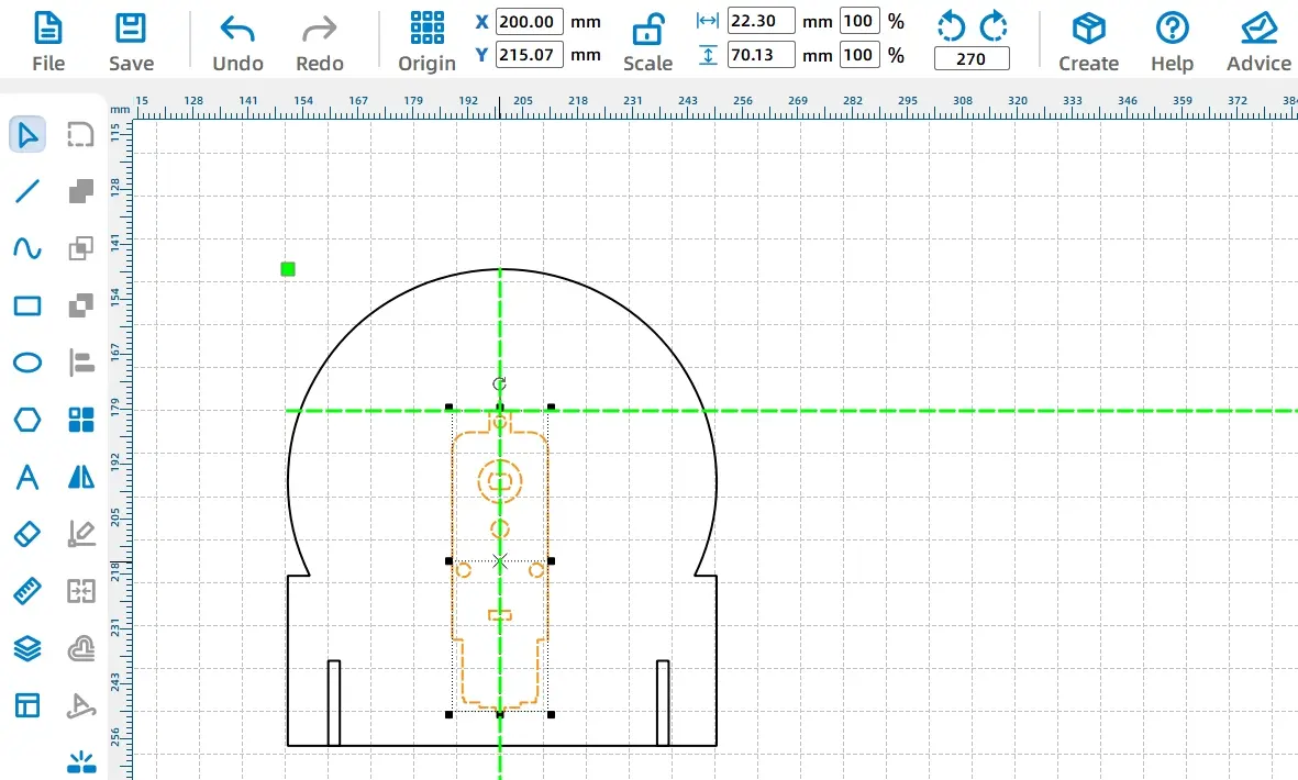
Select the motor graphic and rotate it 270 degrees. Then group the motor graphics so they can be moved and aligned as one object.
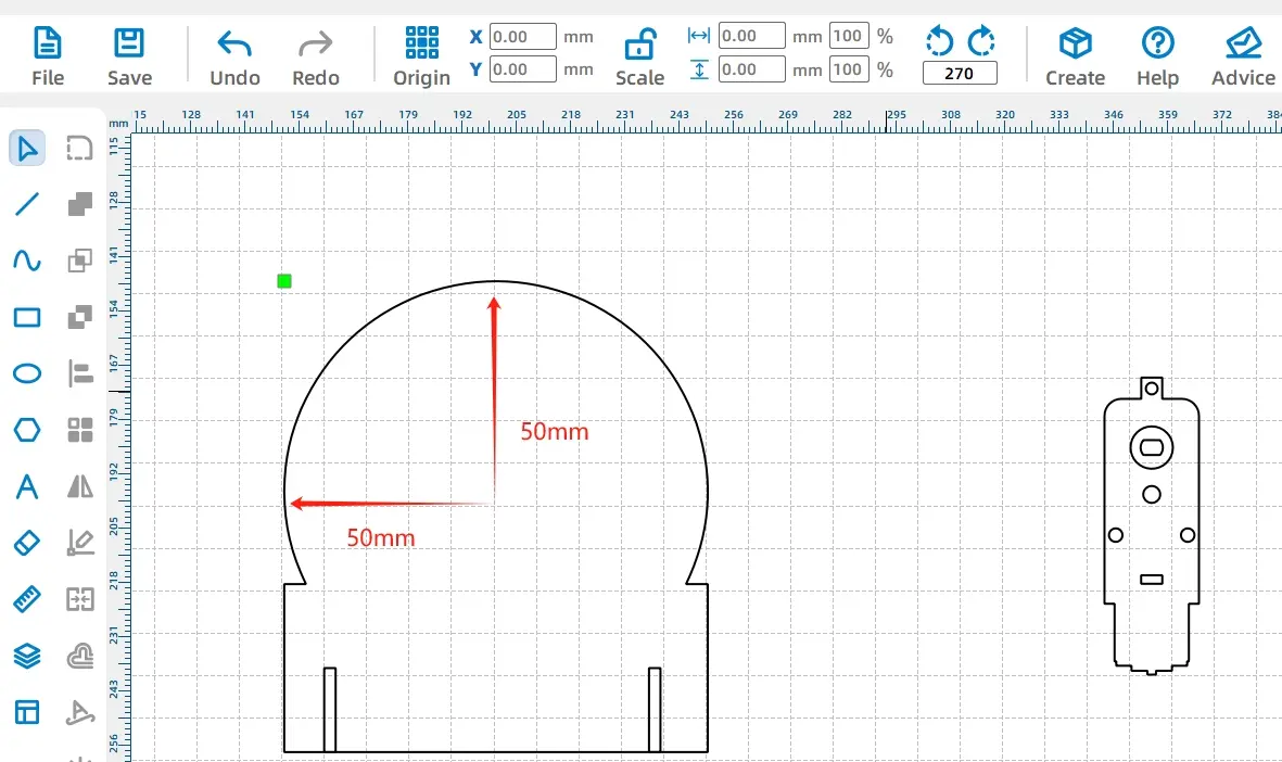
Turn on the Grid Tool and align the motor shaft hole with the center of the rotating disk. Since the disk diameter is 100 mm, the disk center is 50 mm from the top and 50 mm from the side of the circular area.
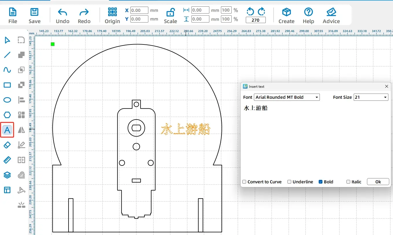
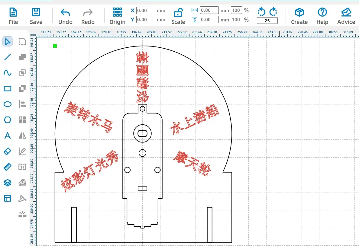
Use the Text Tool to add game item names to the rotating disk. Set the font, size, style, and content in the text window, then place the text on the disk.
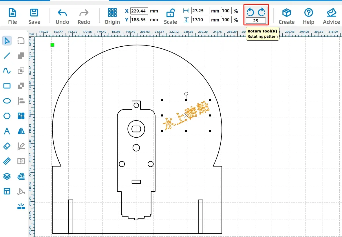
Rotate the text to improve the wheel layout. In the source workflow, one text object is rotated by -25 degrees. After positioning the text, set the text layer to a line or outlining process so it leaves a visible mark without cutting through the wood.
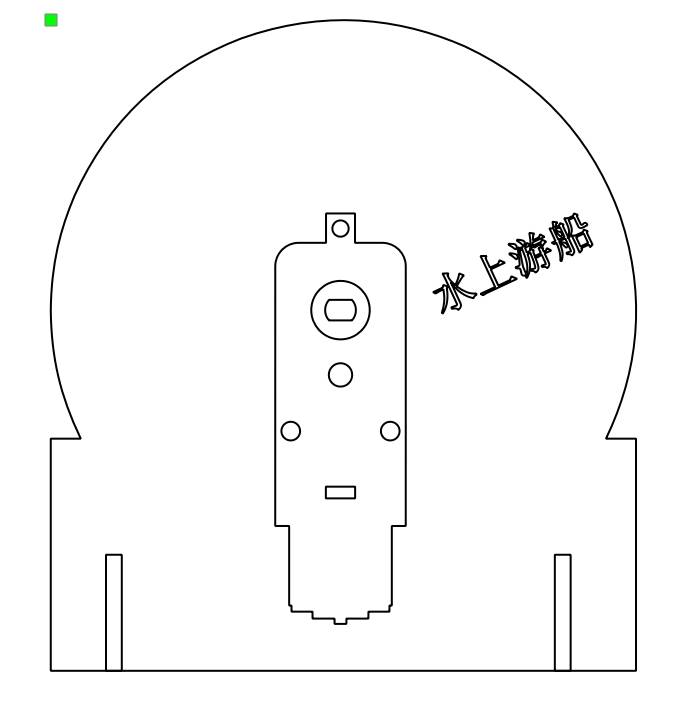
Repeat the same text workflow for the remaining roulette options. The completed rotating disk includes the motor position, mortise slots, and text labels.
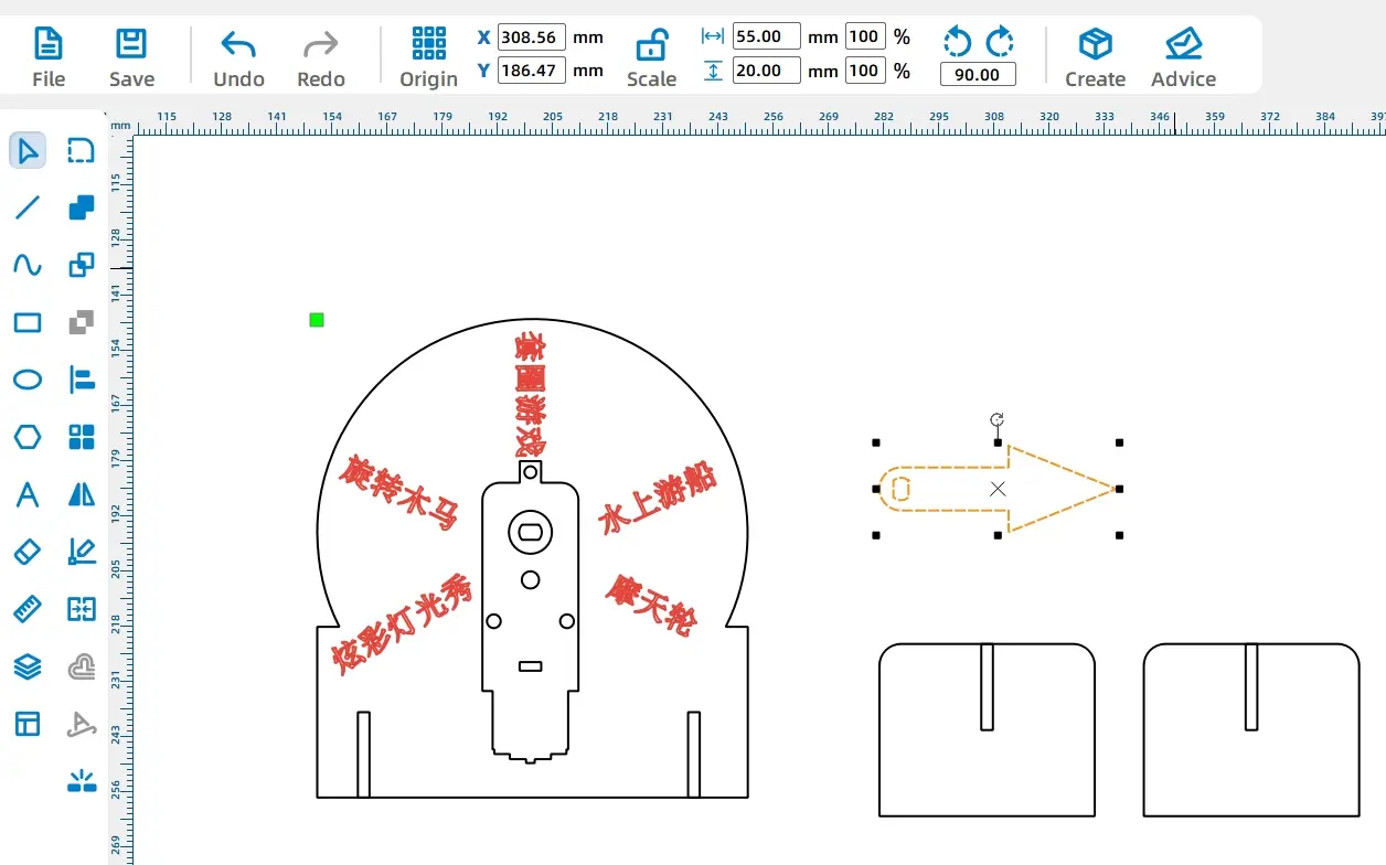
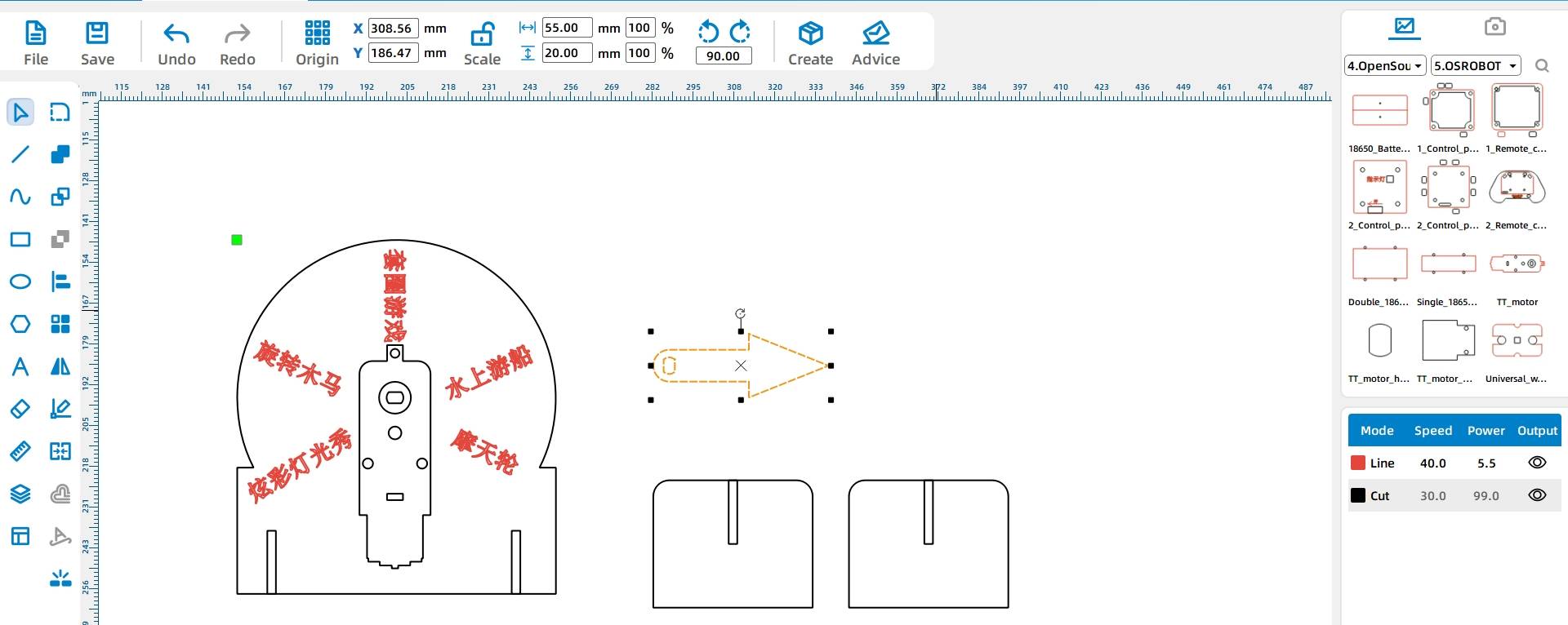
Use the Ellipse Tool to draw a 10 mm circle. Then open Basic Shapes in the Library Panel and choose an arrow shape for the pointer.
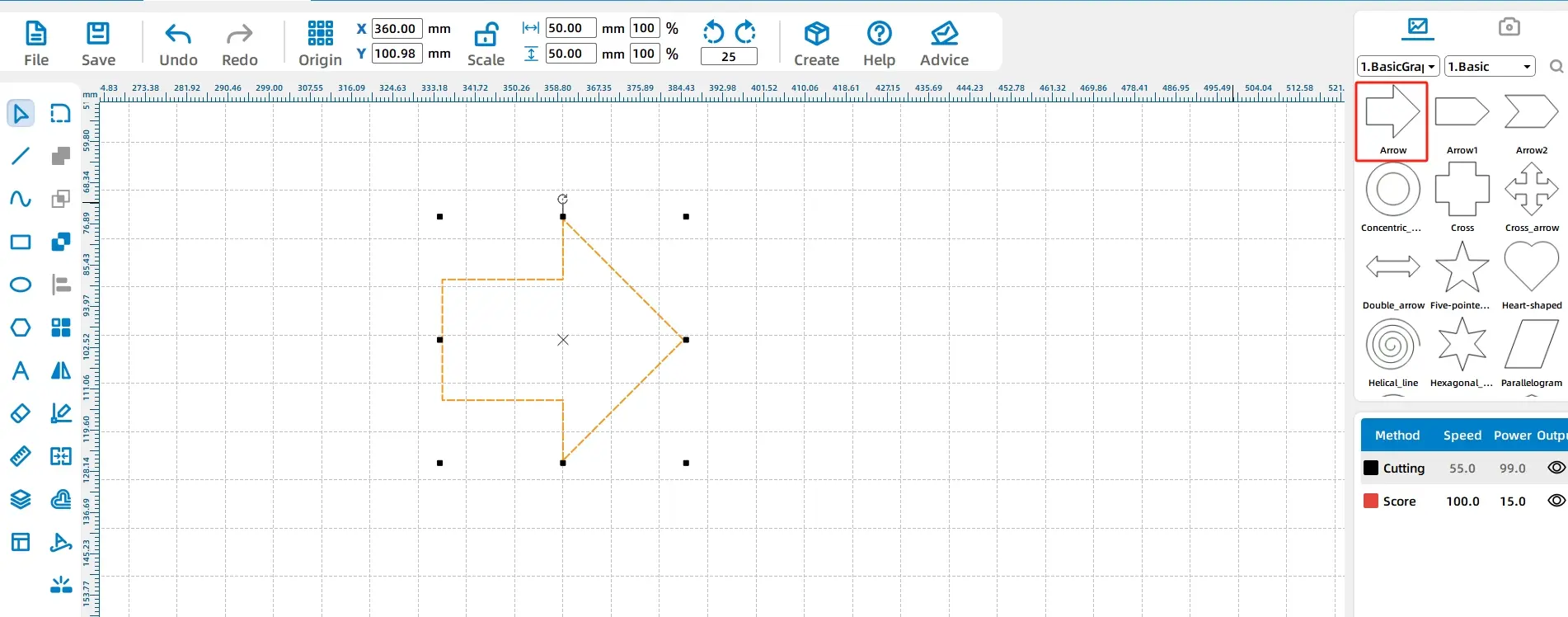
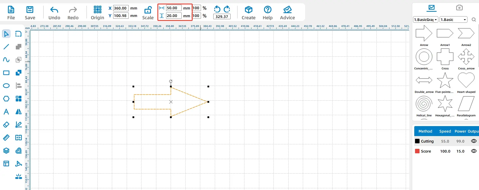
Resize the arrow to 50 mm wide and 20 mm high. Draw a 20 mm circle at the tail of the arrow, then align the circle with the arrow tail.
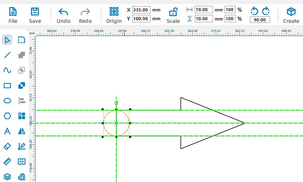
Add a motor shaft hole to the pointer by selecting TT Hole Position from Mechanical Parts in the Library Panel and placing it at the center of the circle.
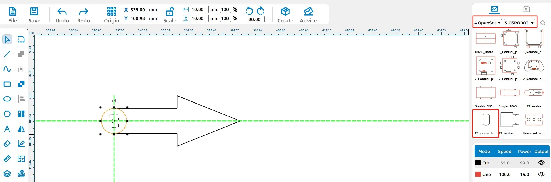
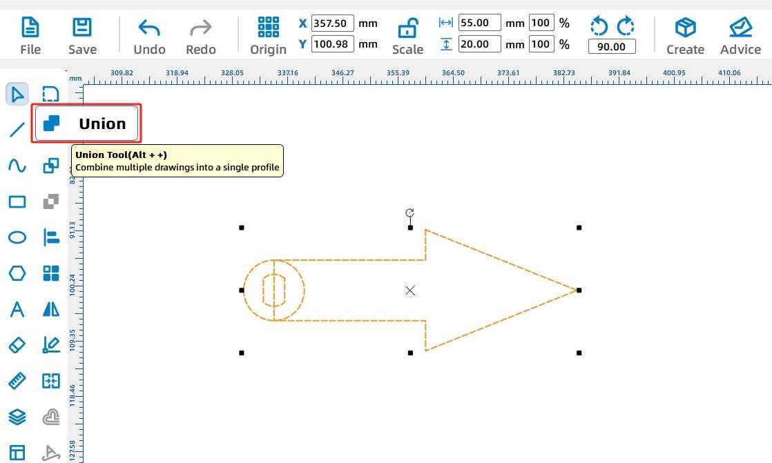
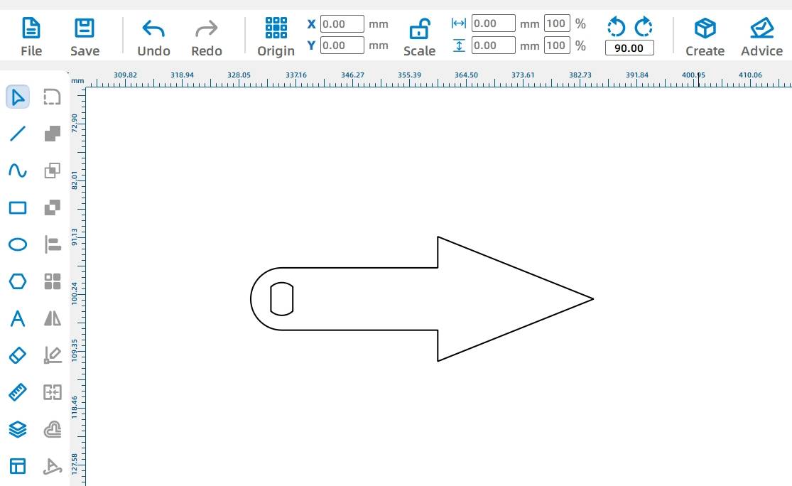
Select the arrow and circle, then use the Union Tool to merge them. The completed pointer should stay within the disk radius so it can spin clearly inside the roulette area.
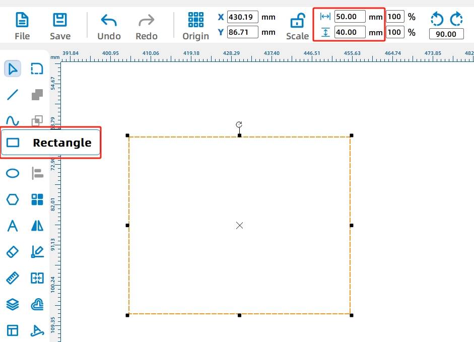
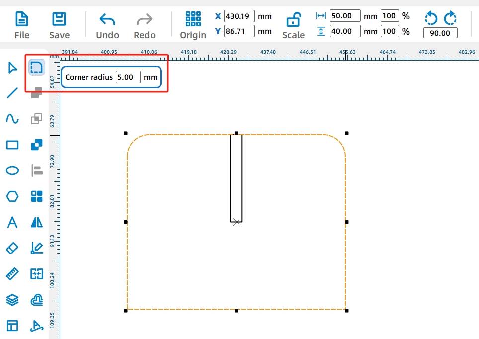
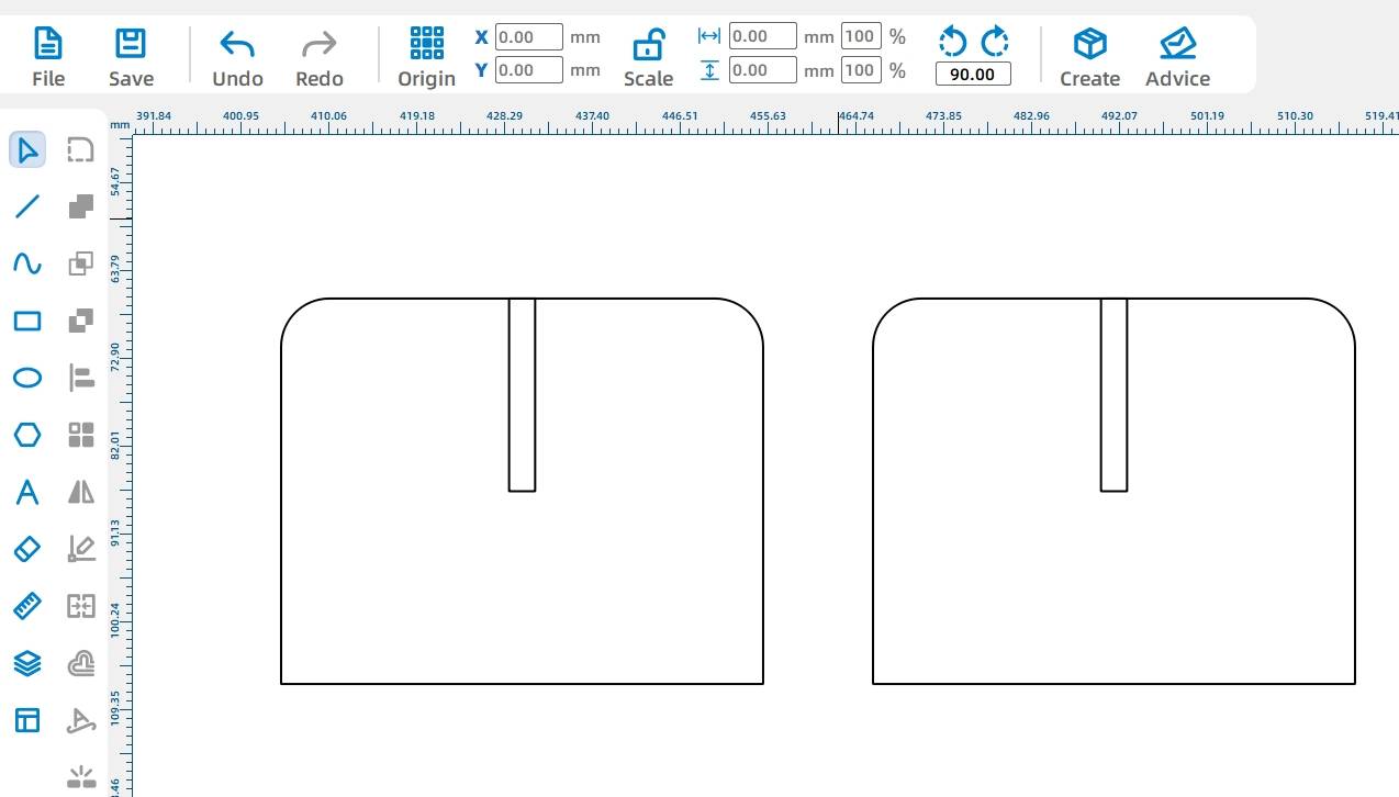
Use the Rectangle Tool to draw a 50 mm by 40 mm rectangle for one support stand. Then draw a small 2.7 mm by 20 mm rectangle as the tenon feature that will fit into the disk mortise.
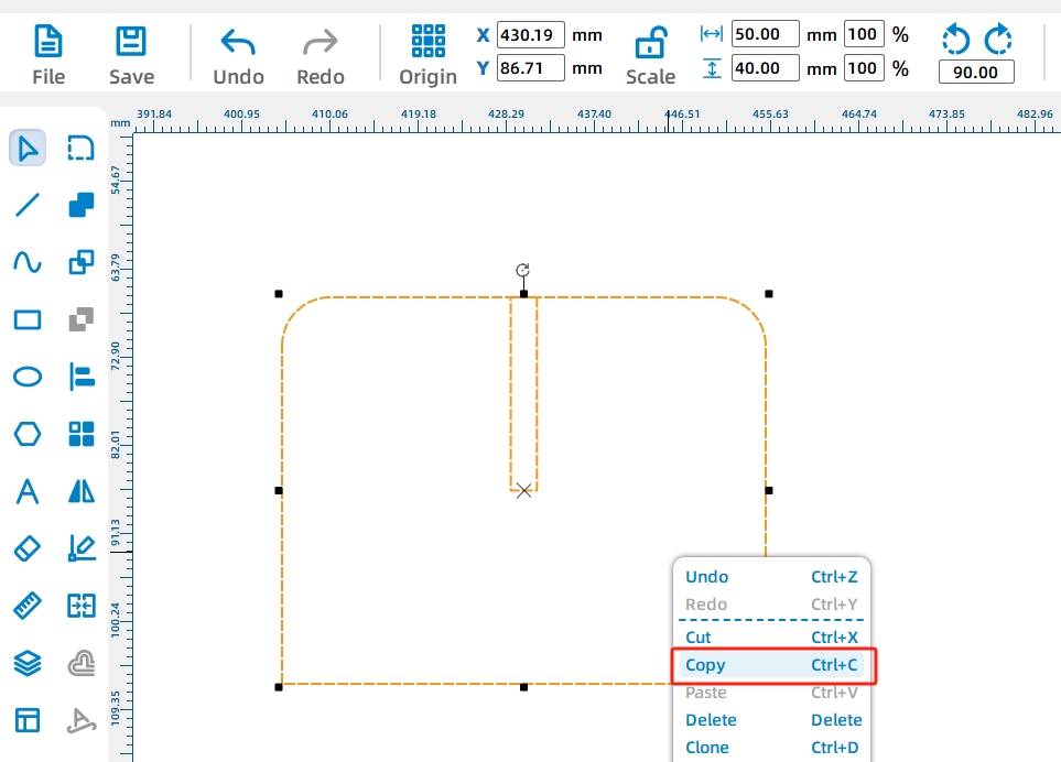
Use the Rounded Corner Tool with a 5 mm radius to round the stand corners. Then copy and paste the stand to create the second support piece.
After removing any unnecessary motor outline from the drawing, review the final design before laser processing.
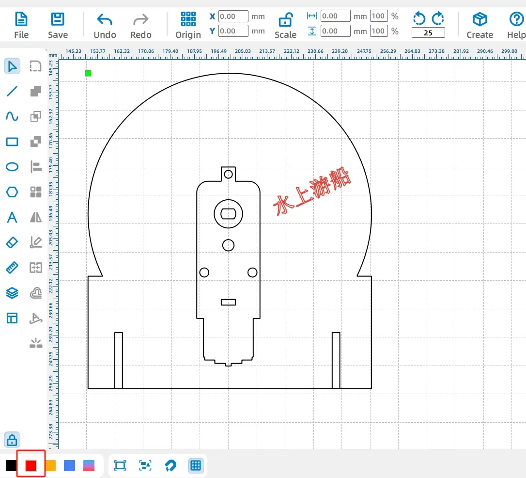
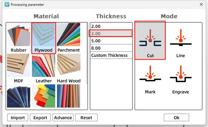
The lucky roulette drawing uses two main laser processes. The text is processed with line tracing so it leaves a visible mark, while the disk, pointer, holes, and support parts are cut through the wood.
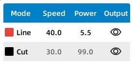
For the red layer, select basswood plywood as the material, choose Line as the processing technique, and set the processing thickness to 0.10.
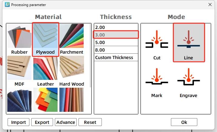
For the black layer, select basswood plywood as the material, choose Cut as the processing technique, and set the processing thickness to 3.00.
Turn on the laser cutting machine and prepare the laser. When the Start Fabrication button is ready, upload the drawing to the laser cutting machine and start processing from the software panel.
After the model structure is prepared, connect the circuit according to the wiring diagram so the lucky roulette can operate with the motor and remote-control components.
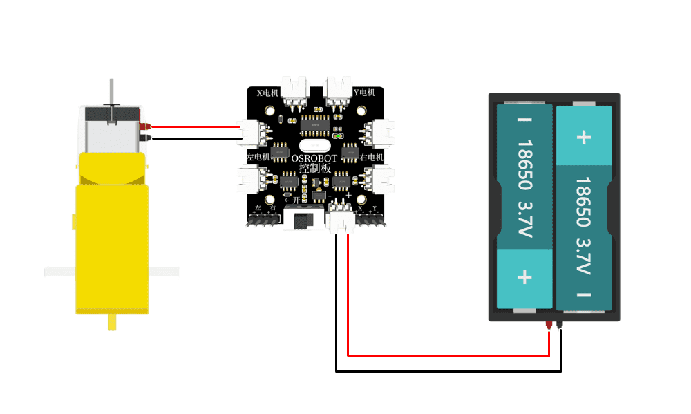
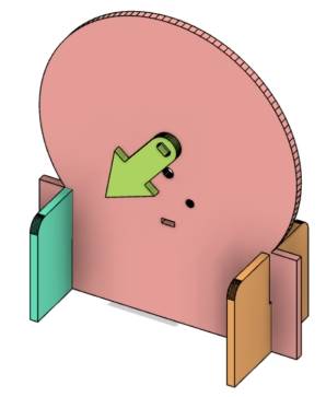
Assemble the model in sequence. First, prepare the motor, rotating disk, and hardware. Fix the motor on the back of the rotating disk. Then install the pointer on the motor shaft hole and insert the two support legs into the disk structure.
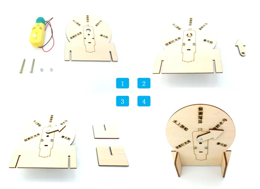
Check whether the pointer spins smoothly after the motor is installed.
Test whether the disk stands securely with the two support legs inserted.
Confirm that the motor shaft hole and pointer hole align correctly.
Review whether the text is readable after line tracing.
Think about how the roulette could allow replaceable text labels so the game options can be changed without cutting a new wheel.
After fabrication, wiring, and assembly, students complete a working lucky roulette that combines laser-cut parts with motorized control. The project demonstrates the full design process from digital drawing to physical creation.
The text on the finished roulette wheel is fixed after tracing. If students want to change the game options later, they would need to create another wheel, which uses extra material. As an extension challenge, students can design a more flexible roulette system with replaceable labels, removable sections, or reusable option cards.
This project is suitable for classroom laser cutters that support cutting and tracing of sheet materials for small robotics and mechanism projects. For schools, makerspaces, and beginner STEAM labs, projects like lucky roulette games, motorized pointers, remote-control structures, and laser-cut classroom game devices can be completed with a classroom laser cutter such as the Thunder Laser Bolt Series.
Teachers can choose the machine and material setup based on classroom space, project size, material thickness, electronic components, and learning goals. The same LaserMaker workflow can also be adapted for other CO2 laser machines when students move on to larger game devices or more advanced robotics projects.
Talk To Our Experts Now!
Please leave your contact information so that we can serve you better.
TAKE THE NEXT STEP WITH THUNDER LASER

 Stable & Consistent MachinesUnlimited ApplicationRobust After-sales SupportFactory Direct Supply


