


PCB Laser Marking Guide: All You Need to Know
 2025-12-14
WHAT ARE YOU LOOKING FOR?
Search Across Products, Blog Posts, Support Content, And Resources.

PCB Laser Marking Guide: All You Need to Know
2025-12-14

A PCB laser marking machine creates permanent identification and traceability information directly on printed circuit boards. It can mark serial numbers, lot codes, QR codes, Data Matrix codes, barcodes, logos, dates, and other production data without applying ink or a separate adhesive label.
The right PCB marking system depends on more than laser power. Manufacturers must consider the PCB surface, code size, required contrast, production volume, positioning method, barcode inspection, variable-data workflow, and whether the equipment will operate offline or as part of an automated SMT line.
This guide explains how PCB laser marking works, what codes can be marked, how UV, fiber, and MOPA lasers differ, when offline or inline marking is more suitable, how to evaluate code quality, and how to choose a PCB laser marking machine for traceability applications.
Quick Answer: A PCB laser marking machine uses a focused laser beam to create permanent text, serial numbers, barcodes, QR codes, or Data Matrix codes on a circuit board.
Depending on the PCB surface and laser wavelength, the process may modify the color of a solder mask, affect a thin coating, change a polymer surface, or create contrast on exposed metal.
UV lasers are commonly tested for FR-4, solder masks, flexible circuits, and other heat-sensitive electronics. Fiber or MOPA lasers may be more suitable for exposed metal areas. Every process should be validated on the actual PCB construction.
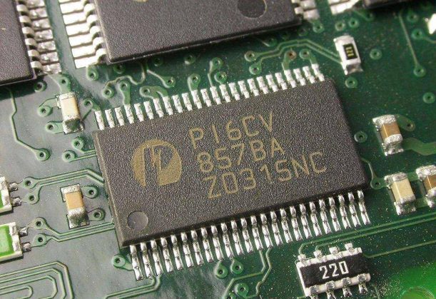
PCB laser marking can create permanent identification codes and production traceability information.
PCB laser marking is a non-contact process used to add permanent identification information to a printed circuit board or assembled PCBA. The content is generated from a digital file, serial-number sequence, spreadsheet, or production database and applied directly to the selected surface.
The marking mechanism varies by material. A laser may create a color change in a solder mask, modify a polymer, remove a very thin coating, or produce contrast on exposed metal. The goal is to create a readable mark without exposing conductors, weakening the solder mask, or damaging nearby circuitry.
For a broader overview of laser marking machine types, marking mechanisms, and general industrial applications, see the laser marking machine guide.
The terms PCB laser marking machine and PCB laser engraving machine are sometimes used interchangeably. However, most traceability applications require a controlled surface mark rather than deep engraving.
Removing too much material may damage insulation, expose copper, or affect nearby traces. QR codes, Data Matrix codes, barcodes, and serial numbers normally need sufficient contrast and consistency rather than significant engraving depth.
A laser PCB machine may refer to several different equipment categories. Before purchasing, confirm whether the machine is intended to identify a finished board or manufacture part of the circuit.
| Equipment | Main Purpose | Typical Process |
|---|---|---|
| PCB Laser Marking Machine | Add permanent identification and traceability data. | QR codes, Data Matrix codes, barcodes, serial numbers, logos, and lot codes. |
| Laser PCB Prototyping Machine | Create or modify circuit structures. | Copper isolation, drilling, microvias, depaneling, or circuit patterning. |
| Laser PCB Printer | An ambiguous term that may describe direct imaging, pattern transfer, or prototyping equipment. | Depends on the actual machine technology. |
| PCB Label Printer | Print a separate label that is attached to the PCB or package. | Thermal-transfer or ink-based label printing. |
PCB laser marking is mainly used for identification and traceability, not for manufacturing the circuit pattern itself.
| Method | Consumables | Variable Data | Durability | Main Limitation |
|---|---|---|---|---|
| Laser Marking | No ink or label is required for the mark itself. | Supports unique codes and serial numbers. | Permanent when correctly validated. | Requires testing for each PCB surface. |
| Inkjet | Requires ink and maintenance supplies. | Supports variable data. | Depends on ink adhesion and curing. | Nozzle maintenance and drying must be controlled. |
| Adhesive Label | Requires labels, ribbon, and adhesive. | Supports variable data. | May peel, lift, or become unreadable. | Adds placement and adhesion variables. |
| Screen Printing | Requires ink, screens, and setup materials. | Limited for serialized data. | Suitable for fixed legends. | Not efficient for unique codes on every PCB. |
Laser marking is useful when PCB identification must support permanent, variable, and serialized data.
A PCB laser marker can apply fixed graphics and variable production data. Typical content includes:
Compatibility depends on the exact marking surface. Solder mask color, coating chemistry, exposed metal, board thickness, nearby traces, and assembled components can all affect the result.
| PCB Surface | Recommended Laser to Test | Typical Application | Main Risk |
|---|---|---|---|
| FR-4 with Solder Mask | UV laser | QR codes, Data Matrix codes, serial numbers, and text. | Burning or excessive removal of the solder mask. |
| Flexible PCB / Polyimide | UV laser | Small codes and compact identifiers. | Warping or carbonization of thin layers. |
| Exposed Copper or Metal | Fiber or MOPA laser | Permanent metal identification. | Damage to electrical contact areas. |
| Aluminum-Backed PCB | Fiber, MOPA, or UV depending on the layer. | Codes on exposed metal or coated regions. | Incorrect laser selection for the coating. |
| Ceramic PCB | UV or another validated source. | Fine text and permanent identification. | Weak contrast or surface damage. |
| Assembled PCBA | Depends on the selected marking area. | Final assembly traceability. | Heating nearby components or solder joints. |
PCB marking compatibility depends on the exact surface, coating, substrate, exposed metal, and nearby components.
Important: A parameter that works on one green FR-4 board may not produce the same contrast on black, white, red, or blue solder masks. Test the actual supplier, board color, coating, and construction.
PCB barcode laser marking is most useful when the physical code is connected to production records. A complete traceability process may link each board to its material batch, process history, inspection results, assembly data, and final product.
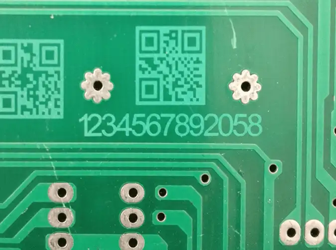
A PCB traceability workflow can combine code generation, positioning, laser marking, reading, and production-result recording.
| Code Type | Best-Fit Use | Main Consideration |
|---|---|---|
| 1D Barcode | Simple identifiers and existing linear-barcode systems. | Requires more horizontal space. |
| QR Code | General identification, service data, URLs, or larger data sets. | Module size, error correction, contrast, and clear surrounding space. |
| Data Matrix | Compact industrial identification and serialized PCB traceability. | Module consistency, contrast, finder pattern, and verification quality. |
QR codes, Data Matrix codes, and 1D barcodes fit different PCB traceability requirements.
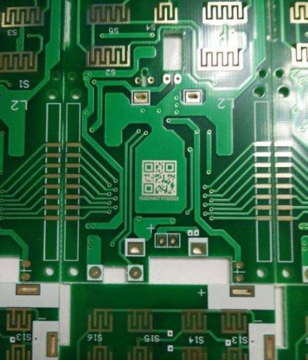
PCB laser marking can create compact barcodes and two-dimensional codes for serialized traceability.
QR and Data Matrix codes are built from small cells called modules. A smaller module allows a more compact code, but it also requires a smaller laser spot, accurate focus, consistent contrast, and a suitable reader.
The smallest possible code is not always the most reliable. Use the largest module size that fits the available space and data requirement.
A reader confirms whether the data can be decoded. A verifier evaluates additional quality characteristics and may assign a grade according to the required inspection method.
A code that scans once is not automatically suitable for production. Test it with the actual production reader, lighting, working distance, board orientation, and required verification conditions.
Serialized PCB marking should prevent the same identifier from being used twice. The marking workflow may check the database before marking, record each completed code, and stop or alarm when a duplicate is detected.
Manufacturers should first decide whether they need a flexible desktop station, an automated standalone system, or a fully integrated inline PCB laser marking machine.
| System Type | Best For | Typical Features | Main Limitation |
|---|---|---|---|
| Desktop / Offline Marker | R&D, prototypes, NPI, repair, low-volume production, and frequent product changes. | Manual loading, flexible fixtures, variable data, and compact footprint. | Relies more heavily on operator loading and positioning. |
| Automated Standalone Station | Medium-volume production requiring more positioning and inspection automation. | Camera alignment, automatic doors, fixtures, code reading, and local data logging. | May not connect directly to the SMT conveyor. |
| Inline PCB Laser Marking Machine | High-volume SMT manufacturing and automated traceability. | Conveyor, fiducial recognition, MES connection, code inspection, and pass/reject control. | Higher integration cost and line-specific configuration. |
Offline and inline PCB laser marking systems differ mainly in automation, data integration, and production-line handling.
An offline PCB laser marking machine is suitable for laboratories, product development, prototypes, small and medium batches, rework, frequent board changes, and production that does not require automatic SMT-line communication.
An inline system is more appropriate when production requires automatic conveyor handling, fiducial correction, panel mapping, MES communication, code verification, duplicate prevention, NG-board handling, or unattended high-volume operation.
A double-sided process may use manual board flipping, an automatic flipping mechanism, or separate upper and lower marking stations. Two laser heads are not required for every double-sided application; the correct configuration depends on cycle time and line design.
The best PCB laser marking machine should be selected from the actual board, code, volume, inspection, and integration requirements.
Identify the solder mask, board color, flexible substrate, exposed metal, ceramic, conformal coating, and nearby components. UV is usually the first option to test for sensitive polymer surfaces, while fiber or MOPA may be more appropriate for exposed metal.
Confirm the maximum PCB size, panel dimensions, code locations, fixture area, and whether several boards must be marked in one setup.
Define the smallest QR code, Data Matrix code, barcode, serial number, and character that the system must produce. Evaluate the finished result with the actual reader or verifier.
Manual fixtures may be sufficient for stable offline production. High-mix or automated applications may require a camera, fiducial recognition, rotation correction, or panel mapping.
Check whether the software supports counters, dates, serial-number sequences, CSV import, databases, QR codes, Data Matrix codes, barcodes, templates, and user permissions.
Decide whether the system only needs to mark, confirm that the code can be read, or measure a quality grade. For inline production, also define the data fields, communication method, result feedback, alarm behavior, and handling of rejected boards.
Select an enclosed system with appropriate interlocks, an emergency stop, a protective viewing window, and effective fume extraction. PCB coatings and polymers may generate fumes and particles during marking.
When comparing a PCB laser marking machine manufacturer in China or another region, request tests on your actual PCB, code inspection results, laser specifications, safety information, software demonstrations, warranty terms, training, and service support.
Record the board supplier, substrate, solder mask color, coating, exposed metal, assembly condition, and nearby components.
Choose the code type, encoded data, module size, surrounding clear space, and position. Avoid traces, contacts, components, board edges, and other graphics that may interfere with readability.
Use a repeatable fixture, locating pins, camera, or fiducial-recognition system. Keep the board flat and prevent movement during marking.
Test speed, power, frequency, focus, line spacing, and passes as applicable. Inspect both the code contrast and the PCB surface for burning, coating removal, deformation, or exposed copper.
Confirm the serial-number sequence or database data, then apply the code within the validated marking window. Use effective extraction and supervise the process.
Decode the marked information, compare it with the assigned production record, and verify its quality where required. Store the code, result, timestamp, work order, and pass/fail status according to the traceability plan.
The best PCB laser marking machine depends on the surface, required code quality, marking area, production volume, and automation level. For offline marking on FR-4 and other heat-sensitive PCB materials, a compact UV laser marker is often the most relevant starting point.

Aurora UV is suitable for offline PCB laser marking, prototype identification, small-batch traceability, QR codes, Data Matrix codes, and serial-number marking on selected PCB surfaces.
The Thunder Laser Aurora UV is an enclosed desktop UV laser marking machine for fine marking on sensitive materials, including PCB and FR-4.
Its main specifications include:
Aurora UV is suitable for PCB development, prototype identification, new-product introduction, small and medium batches, QR code marking, Data Matrix marking, serial numbers, and fixture-based offline production.
System boundary: Aurora UV is a desktop offline marking platform. It is not a complete SMT inline system with conveyor transport, automatic board-width adjustment, MES handshaking, integrated fiducial recognition, and automatic pass/reject handling.
When the marking area is exposed copper, aluminum, a metal shield, housing, or another metal component, the Aurora Fiber or Aurora MOPA may be evaluated.
The correct configuration depends on the metal, coating, required contrast, electrical function, and nearby PCB materials.
Select a dedicated inline PCB laser marking machine when the project requires continuous SMT transport, automatic board recognition, fiducial correction, MES exchange, integrated code verification, automatic NG handling, or unattended double-sided processing.
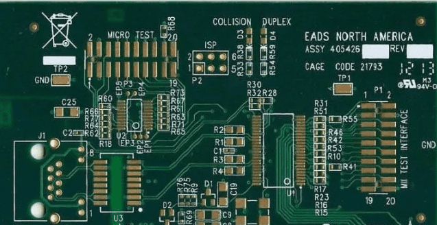
The correct PCB laser marking system depends on the board surface, code quality, production volume, and automation requirements.
| Problem | Likely Cause | Recommended Adjustment |
|---|---|---|
| Code contrast is too low | The laser source or parameters do not produce enough surface response. | Adjust speed, power, frequency, focus, and line spacing, or test another laser source. |
| The code cannot be scanned | Modules are too small, contrast is weak, focus is incorrect, or the surrounding clear area is insufficient. | Enlarge the code, improve contrast, refocus, and test with the production reader. |
| The code scans but is not stable | Board color, surface variation, lighting, or module consistency affects reading. | Test the actual line camera and define a verification requirement. |
| Solder mask burns or copper is exposed | Excessive energy, slow speed, too many passes, or an unsuitable wavelength. | Stop production, reduce heat input, and validate a lower-impact process. |
| Code position shifts | Fixture variation, board tolerance, orientation error, or missing fiducial correction. | Improve the fixture or add camera-based position correction. |
| A serial number is duplicated | Counter, database, restart, or operator workflow error. | Add a duplicate check before marking and record every completed code. |
| The code reads on one scanner but not another | The readers use different lighting, lenses, distances, or angles. | Validate with the actual production-line reader and illumination. |
PCB laser marking problems should be evaluated using the actual PCB surface, production reader, and inspection conditions.
A PCB laser marking machine can create permanent QR codes, Data Matrix codes, barcodes, serial numbers, and production information for electronics traceability. Reliable results require the correct laser source, tested PCB parameters, accurate positioning, readable code design, and a defined inspection method.
Choose an offline UV laser marker for flexible development, prototypes, new-product introduction, and small-to-medium batches. Choose a dedicated inline PCB laser marking machine when the production line requires conveyor handling, fiducial correction, MES integration, automatic verification, and pass/reject control.
Need Help Testing a PCB Laser Marking Process?
Send Thunder Laser the PCB material, solder mask color, board size, code type, minimum code size, production volume, and inspection requirements. Our application team can help evaluate a suitable offline laser marking solution.
Contact Thunder LaserTalk To Our Experts Now!
Please leave your contact information so that we can serve you better.
PCB LASER MARKING MACHINE FAQS
FIND THE RIGHT LASER FOR YOUR NEXT PROJECT
Explore Thunder Laser solutions designed for different materials, workflows, and production needs.


 Stable & Consistent MachinesUnlimited ApplicationsRobust After-sales SupportFactory Direct Supply


