


Bumblebee Mortise-and-Tenon Laser Cutting Project with LaserMaker
 2024-06-29
WHAT ARE YOU LOOKING FOR?
Search Across Products, Blog Posts, Support Content, And Resources.

Bumblebee Mortise-and-Tenon Laser Cutting Project with LaserMaker
2024-06-29

In this STEAM engineering project, students design and make a laser-cut bumblebee model using LaserMaker. The lesson connects insect observation, symmetrical structure, geometric decomposition, mortise-and-tenon joints, thin-part design, tracing, engraving, cutting, and hands-on assembly.
This project helps students turn a natural insect form into a buildable laser-cut model. Students analyze the bumblebee body, face, antennae, wings, and legs, then design each part so it can be cut and assembled with slot-and-tenon connections.
| Item | Details |
|---|---|
| Project | Laser-cut bumblebee mortise-and-tenon model |
| Software | LaserMaker |
| Main Skills | Rectangle Tool, Oval Tool, Rectangular Array, Align Guides, Difference Set, Union Tool, Rotation, tracing, cutting, and assembly |
| Source-Mentioned Materials | Basswood plywood, corrugated paper, and acrylic sheet in the processing example |
| Classroom Fit | Engineering challenges, animal-inspired modeling, mortise-and-tenon structures, maker education, and classroom laser cutting |
Students will design a bumblebee model by breaking the insect into separate parts, drawing each part in LaserMaker, adding mortise-and-tenon connections, setting engraving, tracing, and cutting layers, and assembling the finished model.
For teachers: Use this lesson to connect biology observation, symmetry, part decomposition, joint design, and laser cutting workflow.
For students: Use the project to create a bumblebee model while learning how insect parts can be simplified into laser-cut shapes.
For makerspaces: Use it as a practical introduction to animal models, thin-part cutting, and slot-fit assembly.
Use oval and rectangle tools to draw the bumblebee body, face, wings, antennae, and legs.
Use Union and Difference Set tools to create connected shapes, slots, and tenons.
Use Rotation, Horizontal Flip, Rectangular Array, and Align Guides to create symmetrical insect parts.
Design mortise-and-tenon joints for connecting the body, face, antennae, wings, and legs.
Set shallow engraving, tracing, and cutting processes based on the intended visual and structural result.
Design thinking: Decompose an irregular natural object into clear parts and rebuild it as a laser-cut model.
Computational thinking: Calculate part sizes, tenon sizes, array spacing, rotation angles, and thin-limb feasibility before cutting.
Engineering thinking: Test joint fit, thin-part strength, inclined slot angles, cutting quality, and assembly stability.
Students may study existing insect models for inspiration, but their final work should include their own improvements, creative choices, and school-appropriate design decisions.
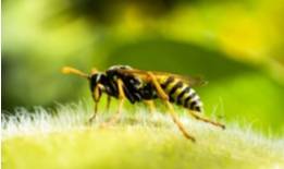
Bumblebees have clear insect features, including a head, thorax, abdomen, three pairs of legs, antennae, compound eyes, and wings. Their body form is mostly symmetrical along the central axis, making them a useful subject for studying part design and mirrored structures.
In this lesson, students observe bumblebee shapes and translate the body, face, antennae, wings, and legs into simplified laser-cut parts that can be assembled with mortise-and-tenon joints.
Before drawing in LaserMaker, students should analyze the bumblebee as both an insect form and an assembled structure.
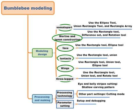
Part shape: The bumblebee is divided into face, body, legs, antennae, wings, and other components. The torso can be built from multiple oval sections.
Modeling method: Ovals, rectangles, Union Tool, Difference Set, Rotation, and array tools are used to create the body and connection features.
Part size: Students should set the size according to the intended ornament or model scale.
Connection method: The body connects with the face, antennae, wings, and legs through inserted mortise-and-tenon joints.
Material selection: The source lesson suggests basswood plywood and corrugated paper, while the processing example uses acrylic sheet.
Process effect: The project uses shallow engraving, tracing, and cutting. The finished model can also be painted after processing.
Students should look at bumblebee images and identify the main body sections, antennae, wings, legs, and symmetry. They should decide the model size and record the dimensions before drawing in LaserMaker.
| Data Recording / Unit: mm | |
|---|---|
| Length: | Body, face, antennae, wings, legs |
| Width: | Body, face, antennae, wings, legs |
| Tenon size: | |
| Mortise size: | |
| Number of mortise-and-tenon joints: | |
After measuring, students should sketch the bumblebee model, including the body, face, antennae, wings, legs, stripe pattern, and joint positions.
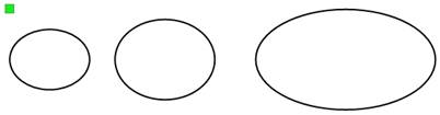
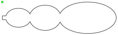
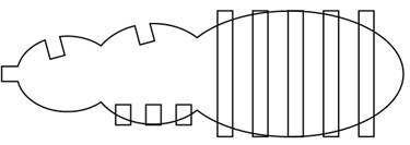
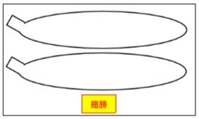
Use the Oval Tool to draw the main body sections. In the source workflow, the head oval is 20 mm wide and 15 mm high, the chest oval is 25 mm wide and 20 mm high, and the abdomen oval is 45 mm wide and 25 mm high.
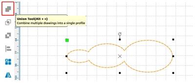
Move the ovals so their ends meet, then use the Union Tool to combine them into one body shape.
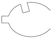
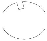
Use the Rectangle Tool to draw a 3 mm square tenon for connecting the body to the face. Align it with the middle of the head and merge it with the body shape.
Use Rectangle Tool, Rotation, and Difference Set to create angled sockets for the antennae and wings. In the source workflow, the rectangles are 3 mm wide and 4 mm high and are rotated by 15 degrees before cutting the sockets.
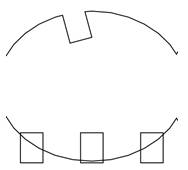
Use the Rectangle Tool and Rectangular Array to draw the leg connection bases on the abdomen, then create stripe shapes for the abdomen using repeated rectangles.
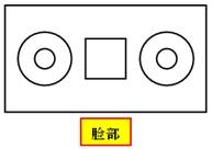
Use the Rectangle Tool to draw the face outline. In the source workflow, the rectangle is 15 mm wide and 8 mm high. Add a 3 mm square in the center as the connection base between the face and the head.
Use concentric circles from the Gallery to create the eyes. In the source workflow, the outer circle is 4 mm and the inner circle is 1.5 mm. Copy the eye shape and align the two eyes on both sides of the face.
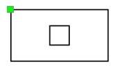
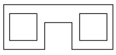
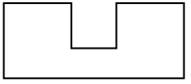
For the antenna base, use the Rectangle Tool to draw a 9 mm by 5 mm rectangle and a 3 mm square. Align the square at the bottom of the rectangle, then use Difference Set to create the slot feature.
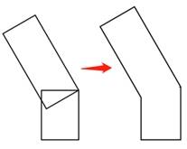
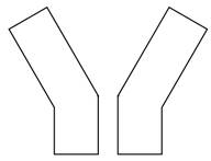
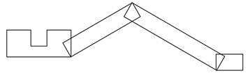
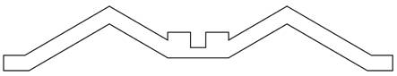
Use rotated rectangles and the Union Tool to create one antenna, then copy and flip it horizontally to form a symmetrical pair. Merge the antennae with the base.
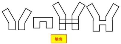
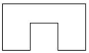
For the wings, draw the base with a rectangle and small square features, then draw the wing shape with an oval and a rotated rectangle tenon. Use the Union Tool to merge the wing into one part.
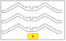
For the legs, first draw the tenon using a rectangle and a square with Difference Set. Then use rotated rectangles to form the leg segments, copy and flip them to make a pair, and use Rectangular Array to create three pairs of legs.
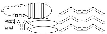
After the body, face, antennae, wings, and legs are complete, review the full bumblebee drawing before setting the processing layers.
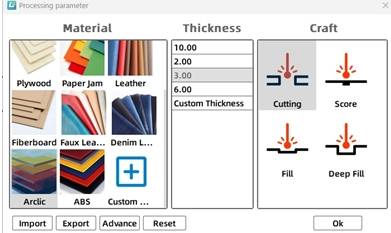
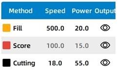
Select the abdomen stripe objects and assign them to the yellow shallow engraving layer. In the source workflow, the material is set to acrylic sheet, the process is set to shallow engraving, and the processing thickness is set to 0.1 mm.
Select the bumblebee face object and assign it to the red tracing layer. In the source workflow, the material is set to acrylic plate, the process is set to tracing line, and the processing thickness is set to 0.1 mm.
Select the remaining bumblebee objects and assign them to the black cutting layer. In the source workflow, the material is set to acrylic plate, the process is set to cutting, and the processing thickness is set to 3 mm.
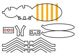
Arrange the process sequence as shallow engraving → tracing → cutting. This helps process surface details first, then line details, and finally the cut outlines.
Compare whether the joints between the face and head, antennae and head, body and wings, and body and legs use the same connection method.
Test whether the mortise and tenon sizes need to be exactly the same, and observe how small size changes affect fit tightness.
Explore whether the six leg joints can also be designed as mortise-and-tenon structures.
Test the cutting result of thin leg parts and adjust parameters if the parts are too fragile or difficult to separate.
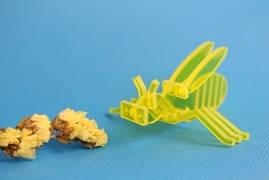
After the final settings are confirmed, students can complete the engraving, tracing, and cutting process, then assemble the bumblebee body, face, antennae, wings, and legs with the designed joints.
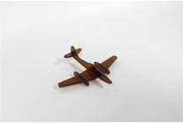
After completing the bumblebee, students can use the same mortise-and-tenon design method to create another animal model. The source lesson suggests drawing a mortise-and-tenon mouse in LaserMaker.

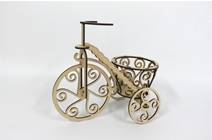
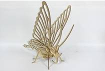
The following examples can be used for classroom discussion and design inspiration. Encourage students to compare part decomposition, joint placement, symmetry, thin-part design, and final assembly results.

This project is suitable for classroom laser cutters that support small-format engraving, tracing, and cutting of sheet materials. For schools, makerspaces, and beginner STEAM labs, projects like bumblebee models, animal structures, mortise-and-tenon models, thin-part ornaments, and flat-pack assemblies can be completed with a classroom laser cutter such as the Thunder Laser Bolt Series.
Teachers can choose the machine and material setup based on classroom space, material thickness, part size, joint fit, and learning goals. The same mortise-and-tenon workflow can also be adapted for other CO2 laser machines when students move on to larger animal models or more advanced engineering challenges.
Talk To Our Experts Now!
Please leave your contact information so that we can serve you better.
NEED HELP FINDING THE RIGHT SOLUTION?
Talk to our team for machine recommendations, application advice, and support based on your needs.

 Stable & Consistent MachinesUnlimited ApplicationRobust After-sales SupportFactory Direct Supply


