


Airplane Inventor Fighter Jet Laser Cutting STEAM Project with LaserMaker
 24-08-14
WHAT ARE YOU LOOKING FOR?
Search Across Products, Blog Posts, Support Content, And Resources.

Airplane Inventor Fighter Jet Laser Cutting STEAM Project with LaserMaker
24-08-14

In this STEAM maker project, students continue the “magic brush” design journey by turning a hand-drawn airplane idea into a laser-cut fighter jet model using LaserMaker. The lesson reviews image scanning, cropping, outlining, engraving, and cutting, then extends the activity with landing gear, welded plates, main wings, tail structure, bayonet-style joints, a small motor, and a propeller.
This project builds on the earlier car inventor lesson. Students use the same draw-scan-process-cut workflow, then learn how an airplane model needs different structural parts, including a fuselage, wings, tail, and landing gear.
| Item | Details |
|---|---|
| Project | Airplane Inventor / fighter jet laser cutting project |
| Software | LaserMaker |
| Main Skills | Hand drawing, image scanning, picture cropping, outline extraction, bitmap engraving, vector cutting, landing gear design, welded plate design, B-spline or curve drawing, mirroring, bayonet-style joints, motor upgrade, and assembly |
| Suggested Materials and Parts | Plywood, paper, drawing pen, small wooden sticks, wooden rings, small motor, propeller, battery box, wires, hot glue or white glue, and optional decorative accessories |
| Classroom Fit | Laser cutting and maker projects, STEAM art and engineering, transportation design, beginner LaserMaker review, creative prototyping, airplane model design, and hands-on classroom assembly |
Students will draw an original fighter jet side view, scan it into LaserMaker, prepare a clean outer cutting contour, engrave the drawing, cut the airplane body, create a three-dimensional version with wings and landing gear, then explore an optional motor-and-propeller upgrade.
For teachers: Use this project to review the car inventor workflow while introducing aircraft structure, curve drawing, mirroring, landing gear, and simple powered motion.
For students: Use the activity to turn a drawing into a laser-cut airplane model and improve it with wings, tail parts, wheels, a motor, and a propeller.
For makerspaces: Use it as a beginner-friendly transportation project that combines creative drawing, laser cutting, assembly, and simple electrical components.
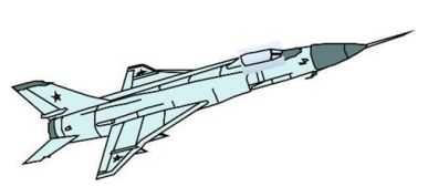
Compare civil aircraft and military aircraft from a design and function perspective.
Identify key airplane model structures, including fuselage, main wing, tail, cockpit area, engine area, and landing gear.
Create a clear side-view drawing and process it in LaserMaker using Picture Crop and Picture Outline.
Design laser-cut landing gear wheels, small wooden rings, welded plates, tail parts, main wings, and bayonet-style joints.
Assemble the model and test an optional small motor and propeller upgrade.
Design thinking: Start from an imaginative airplane drawing, then improve the model with structure, balance, details, and optional motion.
Computational thinking: Use cropping, outlining, layers, dimensions, arrays, mirroring, and repeated parts to prepare a production-ready laser file.
Engineering thinking: Consider wing placement, tail support, landing gear stability, propeller clearance, motor position, and safe wiring.
Students should operate the laser cutter only under teacher or lab supervisor guidance. Before cutting, check focus, layer output, material placement, and processing parameters. When adding a motor and propeller, keep hands, wires, and loose parts away from the rotating propeller, and test the model slowly under supervision.
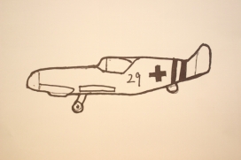
This lesson asks students to make a fighter jet model based on skills learned in the first lesson. The source project uses a BF109-style airplane as the model theme, but teachers can guide students to focus on general aircraft structure, model design, and safe maker practice.
Teachers can begin the lesson with aircraft comparison questions. These prompts help students observe structure, function, and design differences before they start drawing.
In terms of use, what are two broad categories of aircraft?
What is the difference between a passenger airplane and a fighter aircraft?
What are the basic visible structures of a fighter jet model?
What airplane designs or aircraft examples do students already know?
Classroom Discussion: Students can compare civil aircraft and military aircraft by size, purpose, maneuverability, and visible structure. For this maker project, the focus should stay on observation, model design, digital fabrication, and safe assembly.
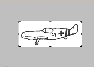
Ask students to sketch the fighter jet they imagine. A side view works best for this project because it gives a clear fuselage outline that can be processed into a cutting contour.
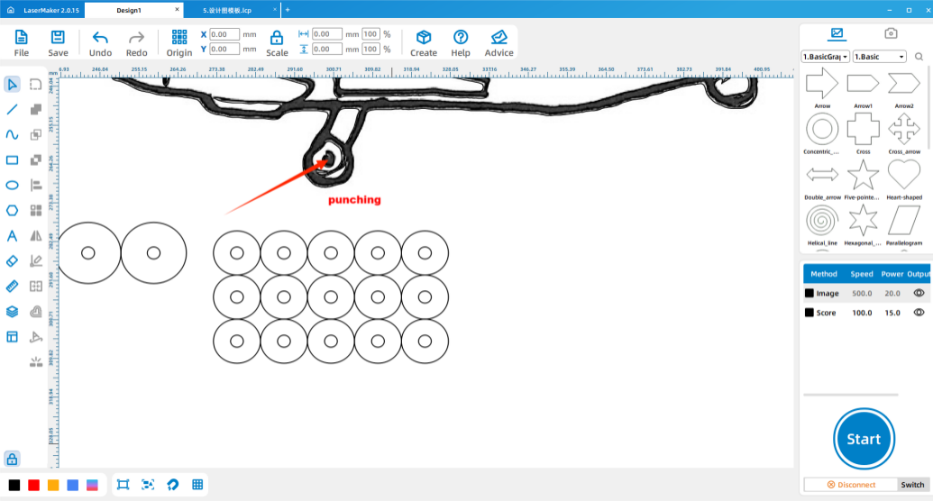
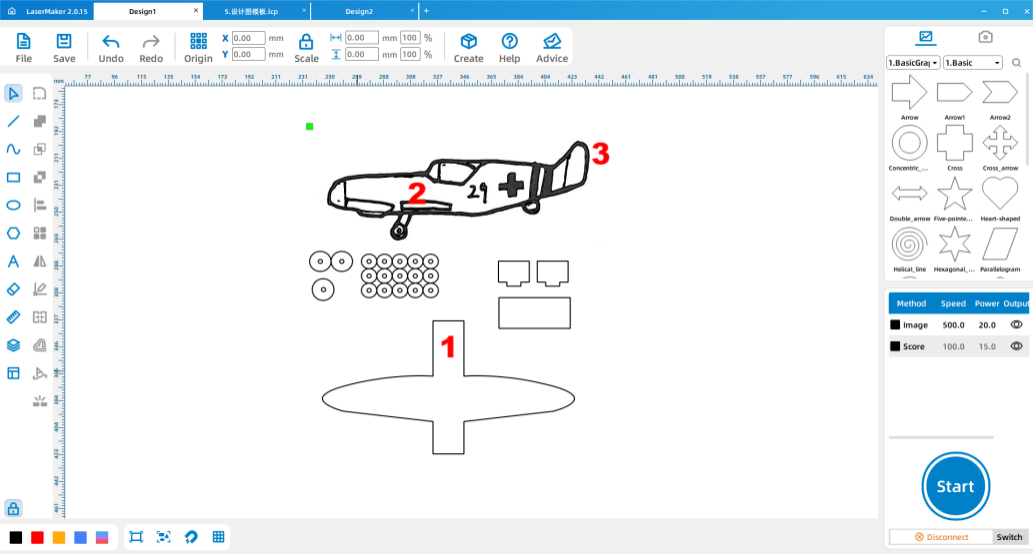
Use a scanning app or another classroom-approved method to scan the drawing and import it into LaserMaker. First, use Picture > Crop to remove blank space around the image.
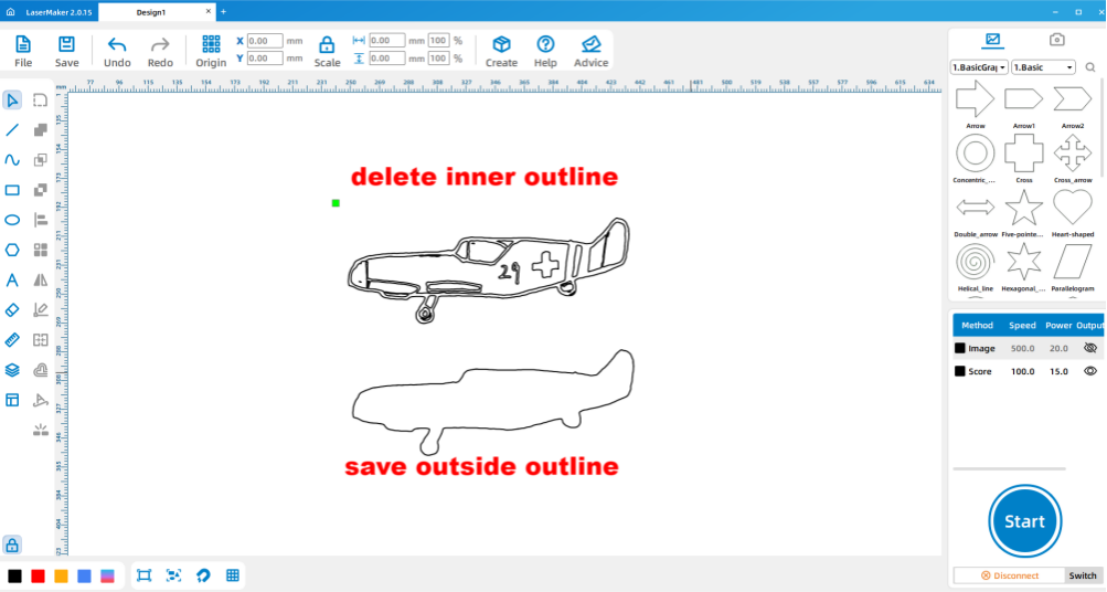
Next, use Picture > Outline to generate the airplane outline. Select and delete the inner outline, keeping only the outer contour for cutting. The original bitmap can remain for engraving so the student’s drawing is still visible on the finished model.
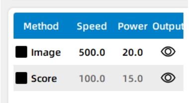
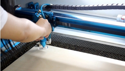
Double-click the layer parameter area in LaserMaker and set the engraving and cutting parameters for the plywood project. After checking the settings, send the file to the laser cutter for processing.
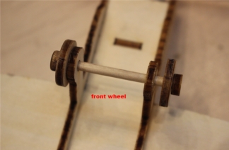
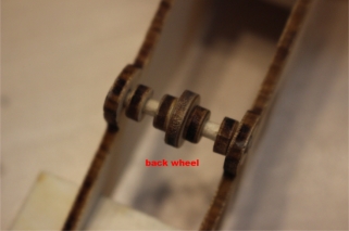
Start by designing the large and small wheels for the landing gear, along with small wooden fixing rings. In the source workflow, the large wheel diameter is 15.53 mm and the small wheel diameter is 11 mm. Add a 3 mm center hole to each wheel position and use Array Copy to create multiple rings.
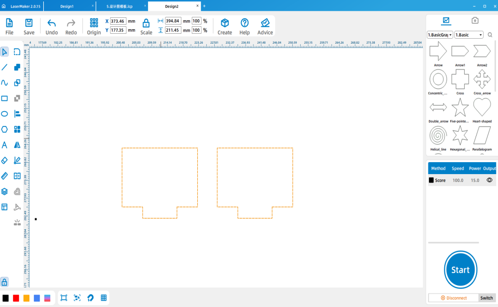
Next, design two welded plates for the fighter jet. The source workflow uses welded plates sized 22 mm by 55 mm, with card features sized 10 mm by 3 mm.
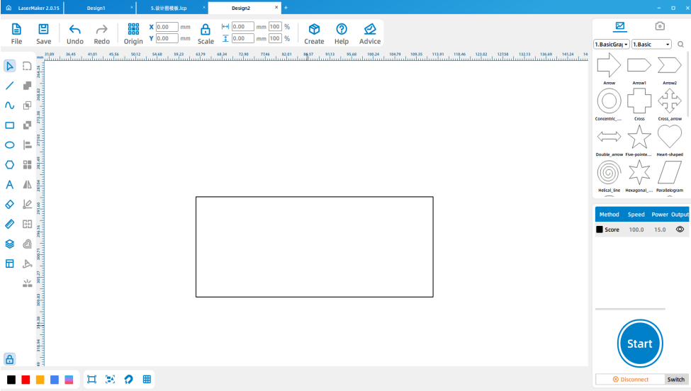
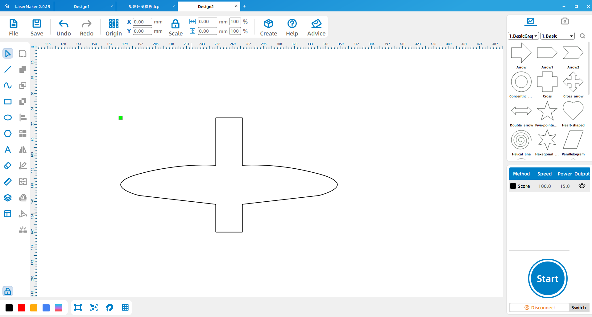
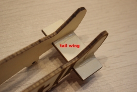
Draw a 50 mm by 20 mm rectangle for splicing the tail section of the fighter jet.
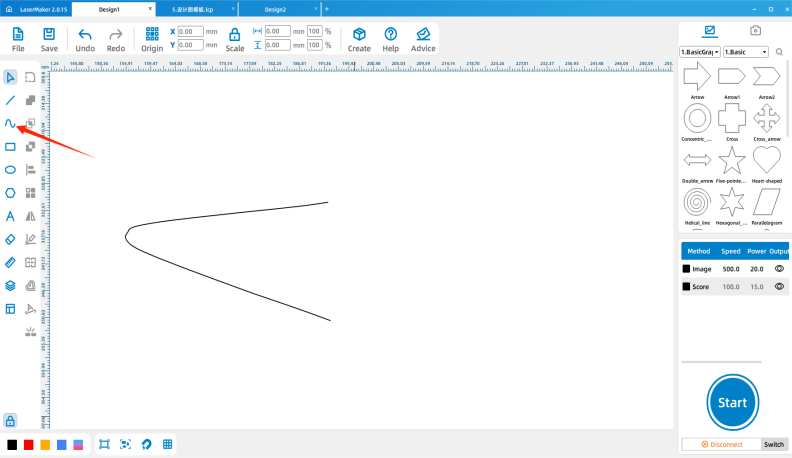
Use the curve and line drawing tool in LaserMaker to draw one side of the main wing. In the source workflow, students click to place points, drag to create arcs, and right-click to finish the drawing.
Tool Tip: Curve tools are useful for airplane wings because they let students create smoother aerodynamic-looking shapes than simple rectangles or straight lines.
Copy and paste the wing, then mirror it for the opposite side. Draw a 22 mm by 95 mm rectangle and use the welding function to connect the wing to the rectangle. Repeat the welding operation for the other side of the wing.
Draw the corresponding bayonet-style joint features and place them according to the source layout. The source workflow lists the bayonet sizes as 20 mm by 2.80 mm, 35 mm by 3 mm, and 10 mm by 2.7 mm.
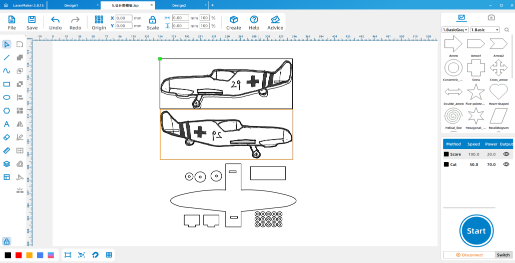
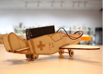
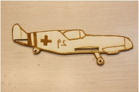
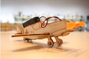
After all parts are designed, send the design file to the laser cutter for processing. Once the parts are cut, splice the welded plates, main wing, and tail into the airplane body. Use hot glue or white glue to reinforce the assembled structure where needed.
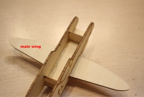
Attach the large and small wheels to the front and rear of the fighter jet using small sticks and wooden rings. In the source workflow, the large wheels are installed at the front and the small wheels are installed at the rear.
Import the saved design files into the laser cutting machine for processing. Before processing, check material placement, engraving and cutting layers, and focal length. The source lesson reminds students to adjust the focus before cutting to reduce the risk of incomplete cuts.
To create a powered display model, students can add a small motor to the front of the fighter jet and install a propeller on the rotating shaft. This upgrade helps students connect the physical model with simple electrical motion.
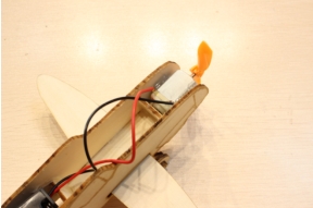
Testing Reminder: The propeller is a moving part. Students should test the motor only with teacher guidance and keep fingers, hair, loose paper, and wires away from the propeller while it is spinning.
Hand drawing: Give students paper and pens, then check that the airplane side view has a clear outer contour before scanning.
Software design: Guide students through importing, cropping, outlining, deleting inner contours, setting layers, creating landing gear wheels, and drawing the wings.
Machine processing: Process student files in a safe classroom order and confirm focus before cutting.
Assembly: Let students assemble the body, welded plates, wings, tail, landing gear, and optional motor upgrade with teacher support.
Review the car inventor workflow before introducing the airplane project so students understand what is being reused and what is new.
Encourage students to focus on model structure and safe making rather than competitive or weapon-focused details.
Prepare spare wheels, wooden rings, small sticks, and welded plate parts when class time is limited.
Use batch processing when appropriate by arranging several student airplane parts into one laser processing file.
Ask students to compare how wing shape, landing gear placement, and tail support affect the model’s appearance and stability.
What are the basic visible structures of a fighter jet model?
How is an airplane model different from the car and train models made in earlier lessons?
How could you improve your airplane model’s balance, appearance, or powered motion?
Students can evaluate their own work and give peer feedback based on creativity, structural firmness, appearance, and learning attitude.
| Evaluation Item | Self-Evaluation | Peer Evaluation |
|---|---|---|
| Creativity, 30 points | ||
| Firmness, 30 points | ||
| Appearance, 20 points | ||
| Learning Attitude, 20 points | ||
| Total, 100 points |
At the end of the lesson, students can display their airplane models, explain how they designed the fuselage, wings, tail, landing gear, and optional motor upgrade, and discuss what they would improve in the next version.


After finishing the basic airplane model, students can redesign the wing shape, adjust the landing gear positions, improve the tail support, or compare different propeller and motor placements. They can also design an airport runway, hangar, display stand, or classroom flight-history exhibit to extend the project environment.
For a broader creative challenge, students can use the same draw-scan-process-cut-upgrade workflow to design other vehicles, such as gliders, helicopters, rockets, boats, trains, or future transportation concepts.
This project is suitable for classroom laser cutters that support engraving and cutting of thin plywood for student maker activities. For schools and beginner STEAM labs, projects like hand-drawn airplane models, wings, landing gear, and beginner LaserMaker activities can be completed with a classroom laser cutter such as the Thunder Laser Bolt Series.
Teachers can choose the machine and material setup based on classroom space, student supervision needs, material thickness, project size, and ventilation setup. Students should always test settings, check focus, and follow the school’s laser safety rules before final cutting.
Talk To Our Experts Now!
Please leave your contact information so that we can serve you better.
TAKE THE NEXT STEP WITH THUNDER LASER

 Stable & Consistent MachinesUnlimited ApplicationRobust After-sales SupportFactory Direct Supply


