STEAM Design and Build DIY Ambient Lighting Project
 2024-08-23
WHAT ARE YOU LOOKING FOR?
Search Across Products, Blog Posts, Support Content, And Resources.

STEAM Design and Build DIY Ambient Lighting Project
2024-08-23

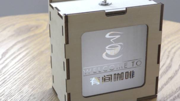
Ambient lighting, also known as LED ambient lighting, is widely used in theme parks, hotels, homes, exhibitions, commercial spaces, and artistic lighting projects. By changing patterns, colours, and lighting styles, ambient lights help create different moods for different spaces.
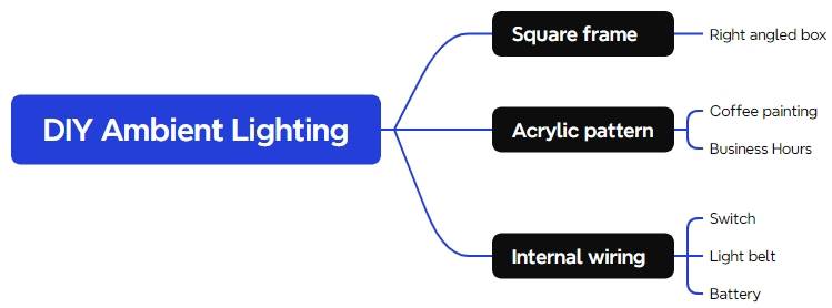
In this laser STEAM course, students will design and build a DIY ambient light. The project combines a laser-cut square frame, engraved acrylic patterns, LED lighting, a rocker switch, battery power, wiring, and structural assembly. It is a more advanced maker activity that encourages students to connect digital fabrication with practical electronics.
The ambient light structure is built around a square frame. Acrylic pattern panels are inserted into the frame, while the LED strip, battery, charging board, switch, and wires are arranged inside. Students will learn how a decorative object can combine structure, visual design, and functional circuitry.
Ambient lighting is used in both private and public spaces to shape how people feel in an environment. A warm light can make a home feel comfortable, while a themed light design can support the atmosphere of a hotel, exhibition, shop, or creative display.
This project helps students connect design with function. They are not only drawing decorative patterns, but also thinking about how the frame holds the acrylic, how light passes through engraved areas, and how the circuit fits safely inside the product.
| Number | Material or Component | Quantity |
|---|---|---|
| 1 | 3 mm acrylic | 1 |
| 2 | 3 mm basswood | 1 |
| 3 | 3-pin 2-position rocker switch | 1 |
| 4 | Dupont connector wire | Several |
| 5 | 5V LED light strip | 1 |
| 6 | Ultra-small 3.7V/4.2V lithium battery charging board | 1 |
| 7 | 3.7V lithium-ion battery | 1 |
| 8 | Soldering iron | 1 |
Classroom note: This is a more advanced project because it includes circuit connection and soldering. Teachers should supervise soldering, battery handling, circuit testing, laser processing, and final assembly.
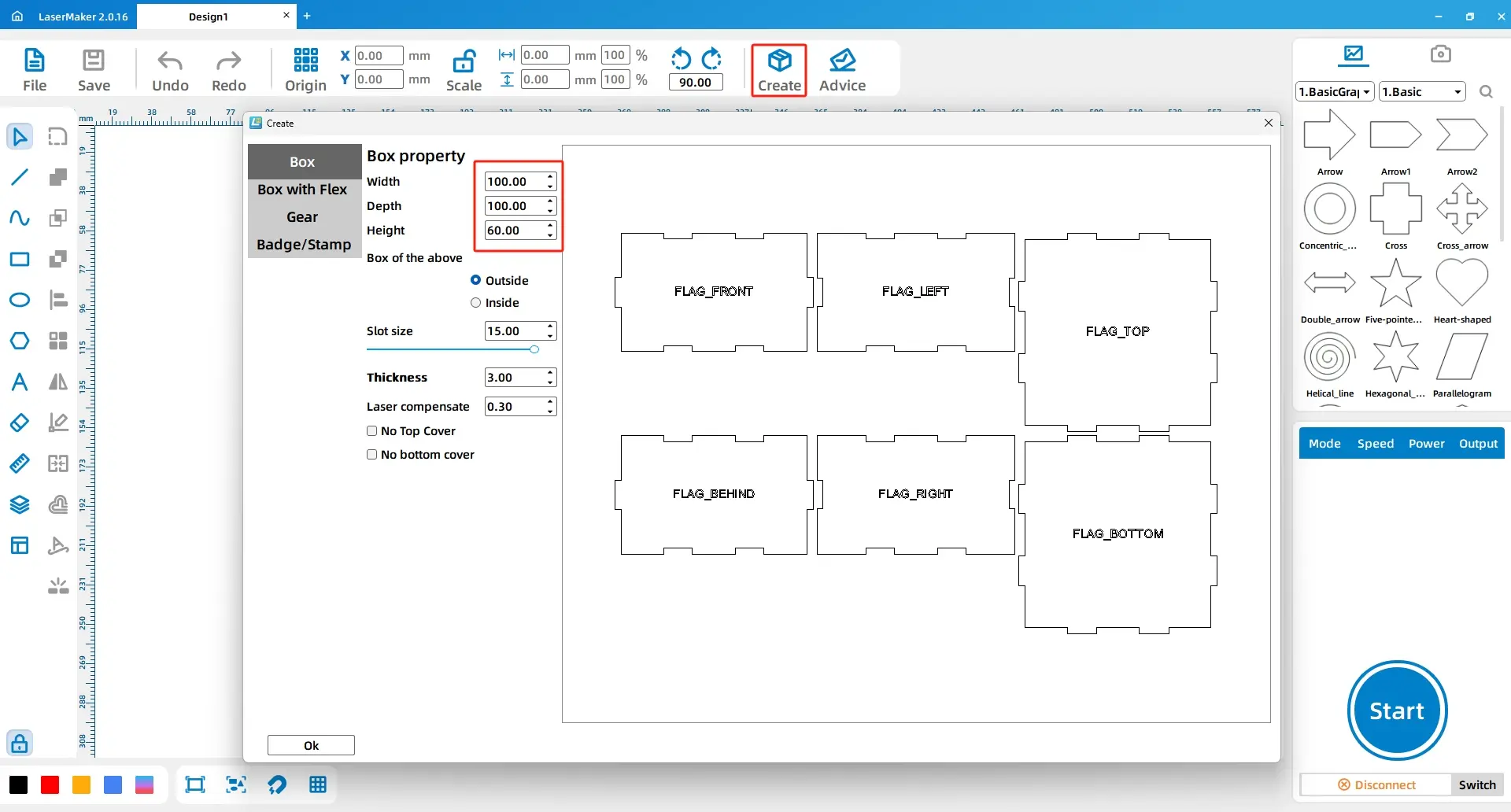
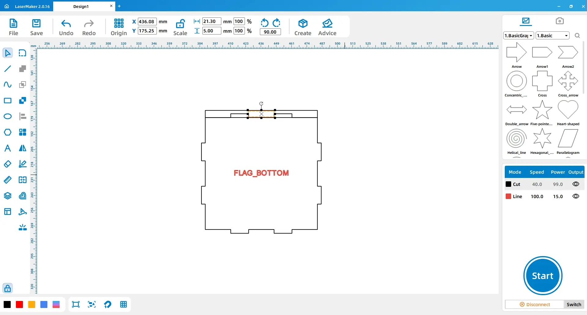
Click the Creation button in the top toolbar, select Right-angled Box, and set the length, width, and height to 100 mm, 100 mm, and 60 mm. Set the groove size to 15 mm.
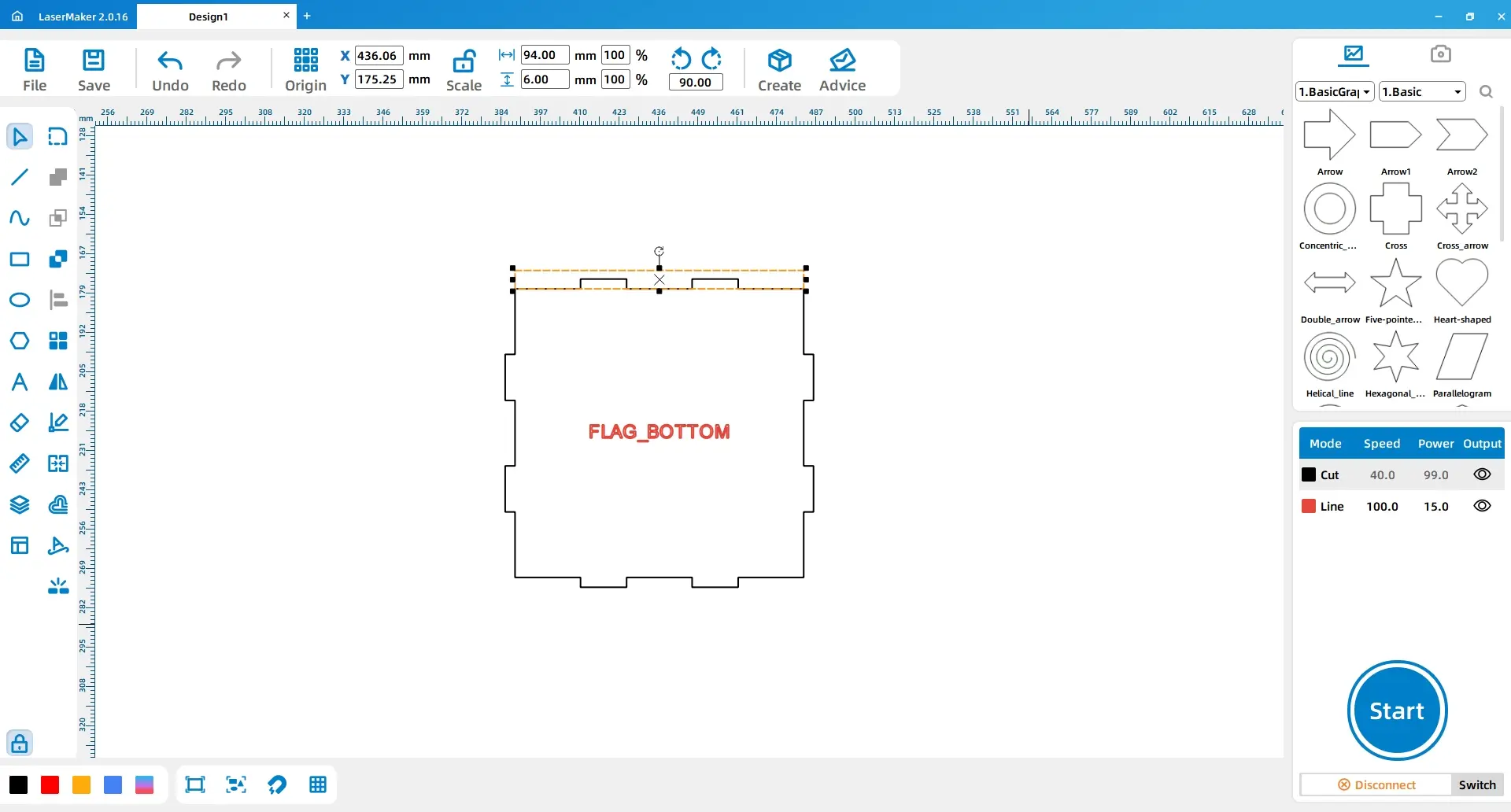
Use the Rectangle tool to draw a 94 mm × 6 mm rectangle and place it above the lower cover. Then draw a 21.3 mm × 5 mm rectangle and place it in the centre of the groove above the lower cover.
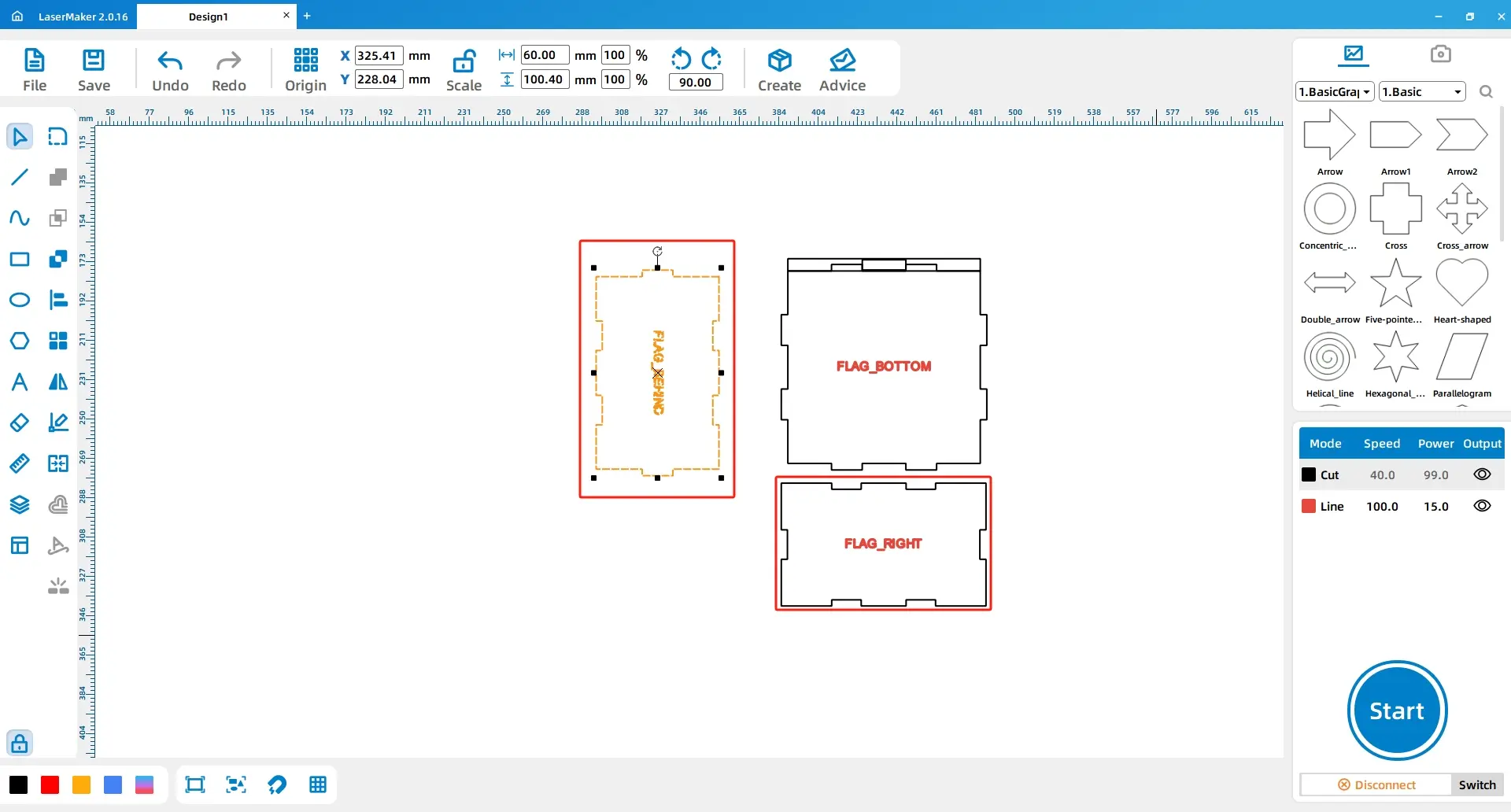
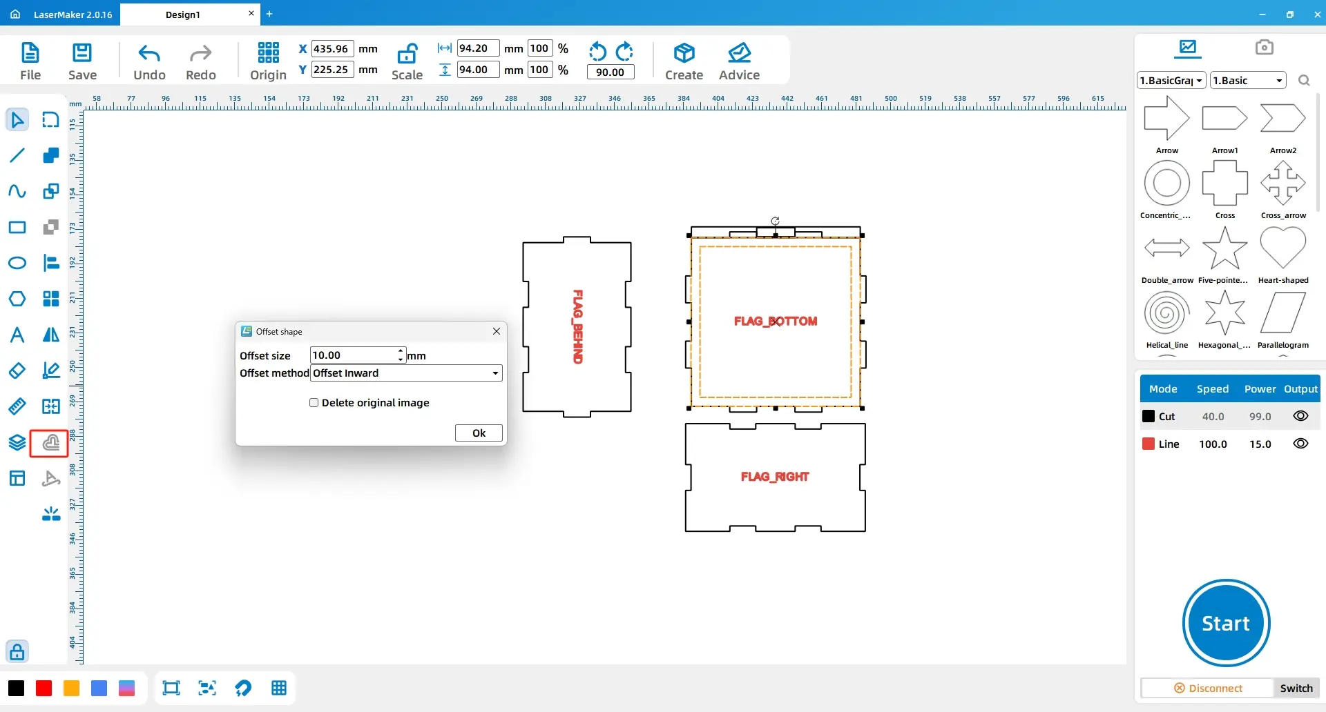
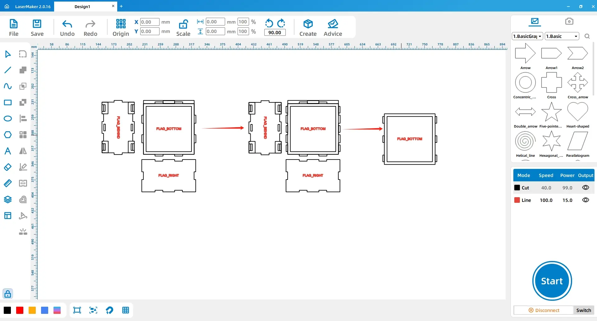
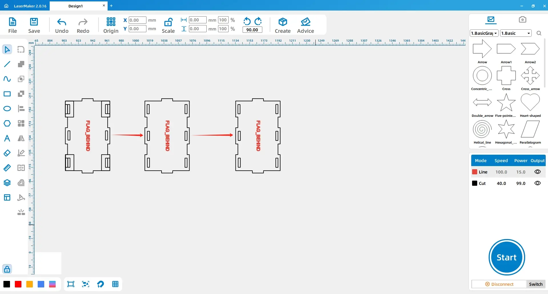
Rotate the rear cover by 90° and move it to the left side of the lower cover. Move the right cover to the bottom of the lower cover. Then draw a 94 mm × 94 mm rectangle in the middle of the lower cover. Select the rectangle, use Offset Curve, and set the offset to 10 mm inward.
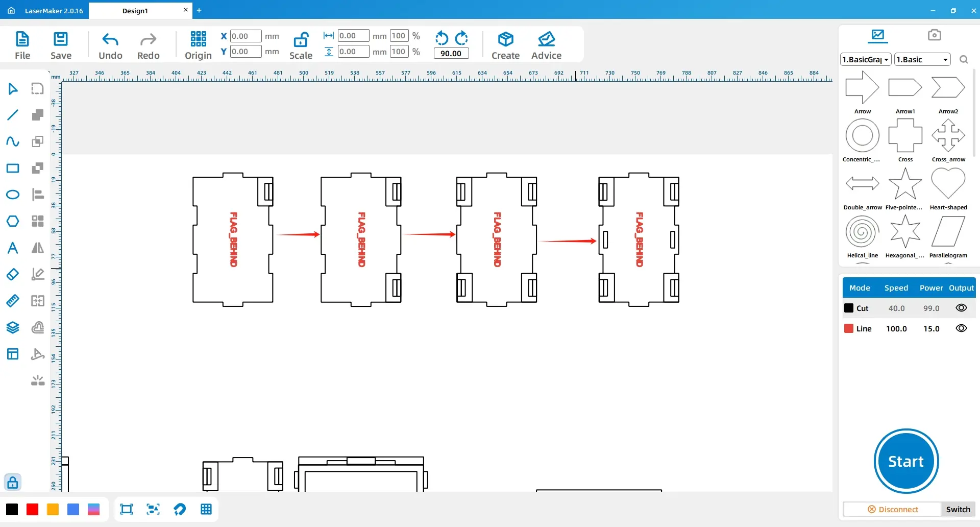
Draw three rectangles: one 10 mm × 21.6 mm rectangle and two 3 mm × 10 mm rectangles. Align the larger rectangle to the upper-right corner of the lower cover, connect the smaller rectangles, and align them to the right of the larger rectangle. Copy, paste, mirror, and arrange these rectangle groups around the lower cover according to the design reference.
Duplicate selected rectangle groups and place them on the left and right sides of the lower cover. Select the outer rectangle and the six side rectangles, then apply Union.
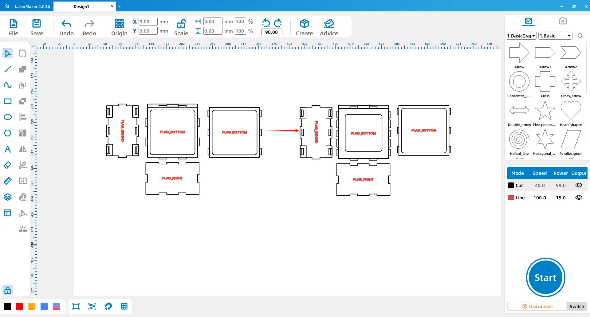
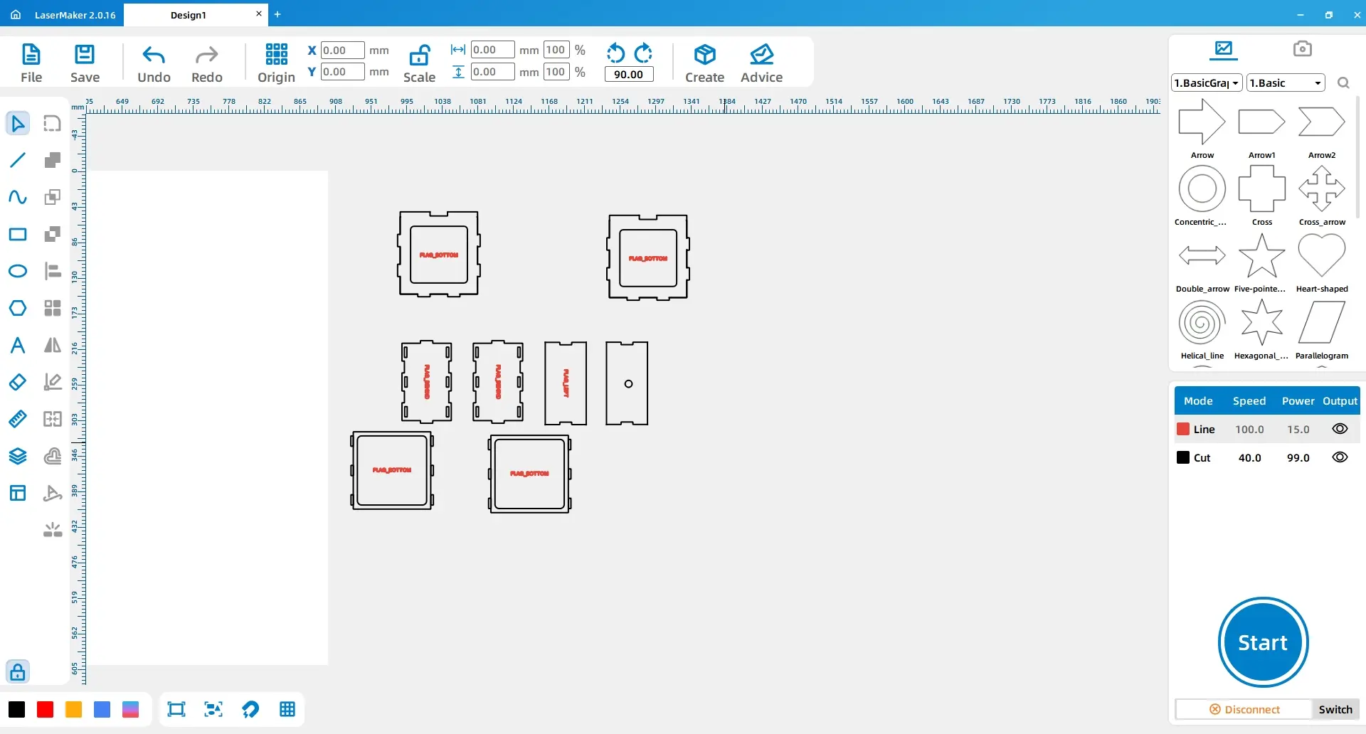
Apply a rounded corner radius of 5 mm to the inner rectangles of both lower covers. Delete the three rectangles on both sides of the left lower cover and change the inner rectangle size to 65 mm × 65 mm.
Select the lower cover and the long rectangle above it, then apply Union. Delete the large rectangle in the lower cover. Select the small rectangle above the lower cover and use Difference. Finally, set a rounded corner radius of 3 mm for the grooves.
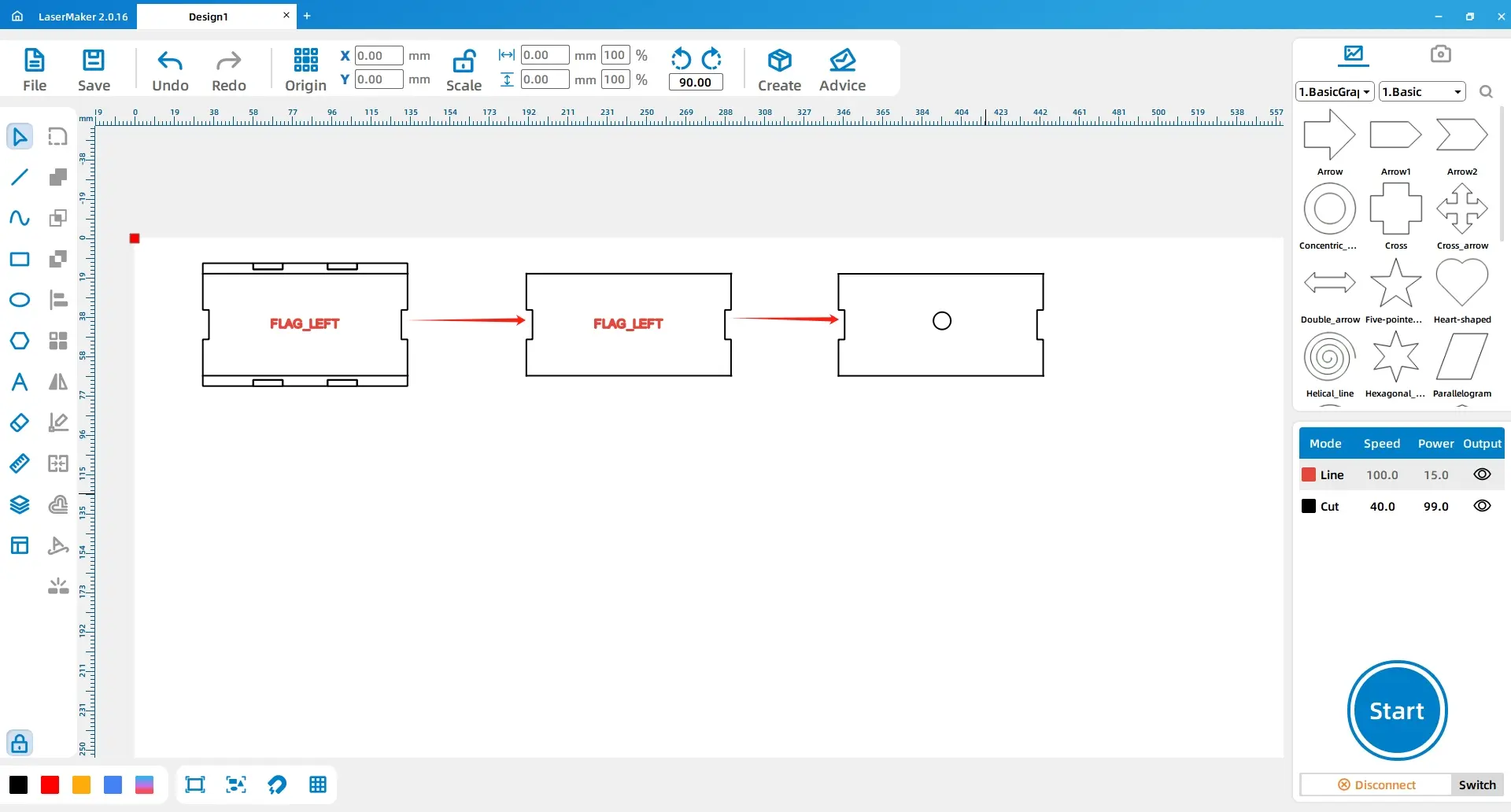
Draw two 100 mm × 6 mm rectangles and place them on the top and bottom sides of the left cover. Use Difference on each rectangle. Draw a 6 mm diameter circle and align it horizontally at the centre of the left cover.
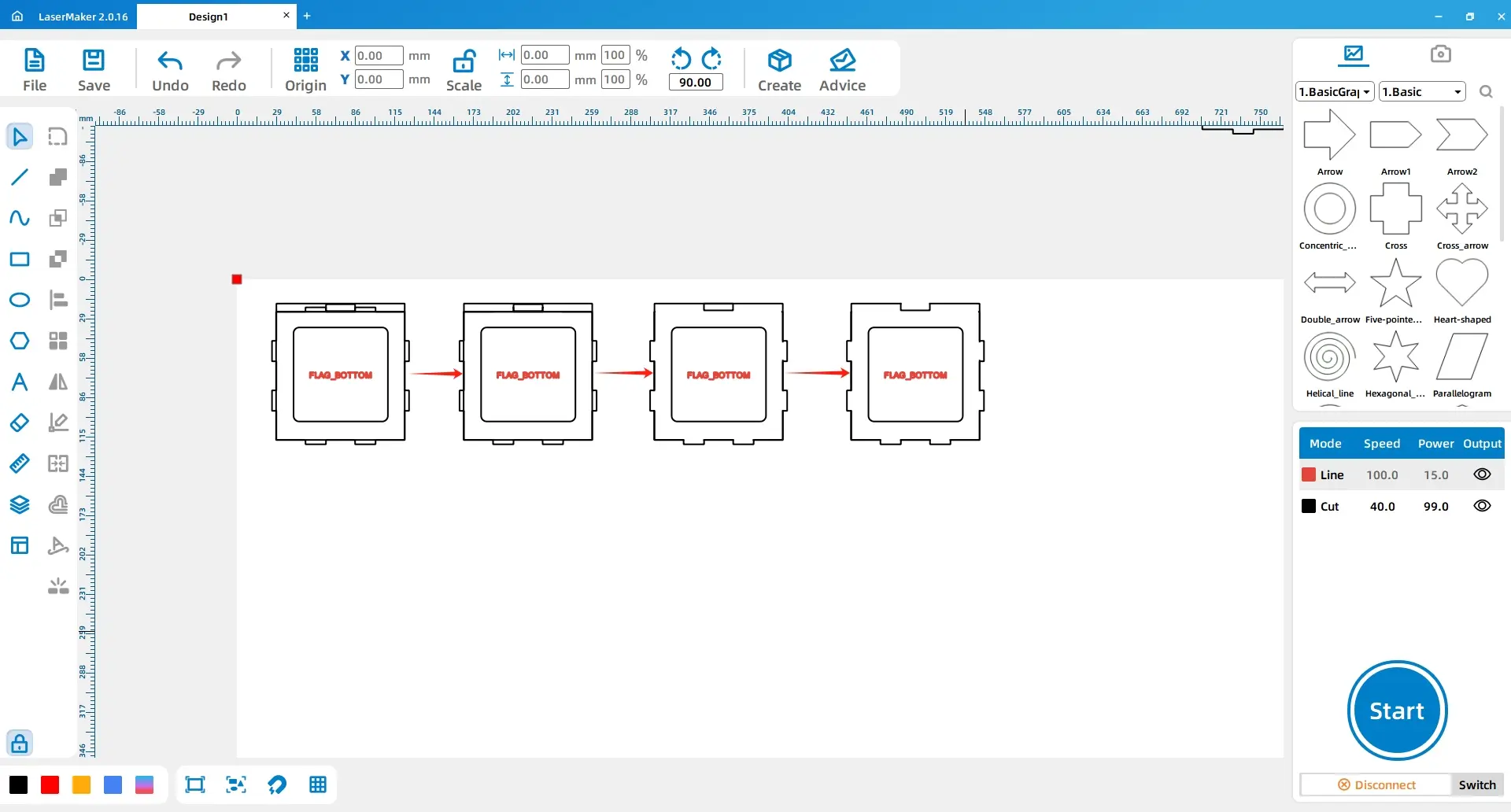
Delete the extra rectangles from the back cover. Then reduce the width and height of each of the six rectangles in the back cover by 0.3 units. Duplicate and paste the two lower covers and the back cover once to obtain all drawings for the square frame.
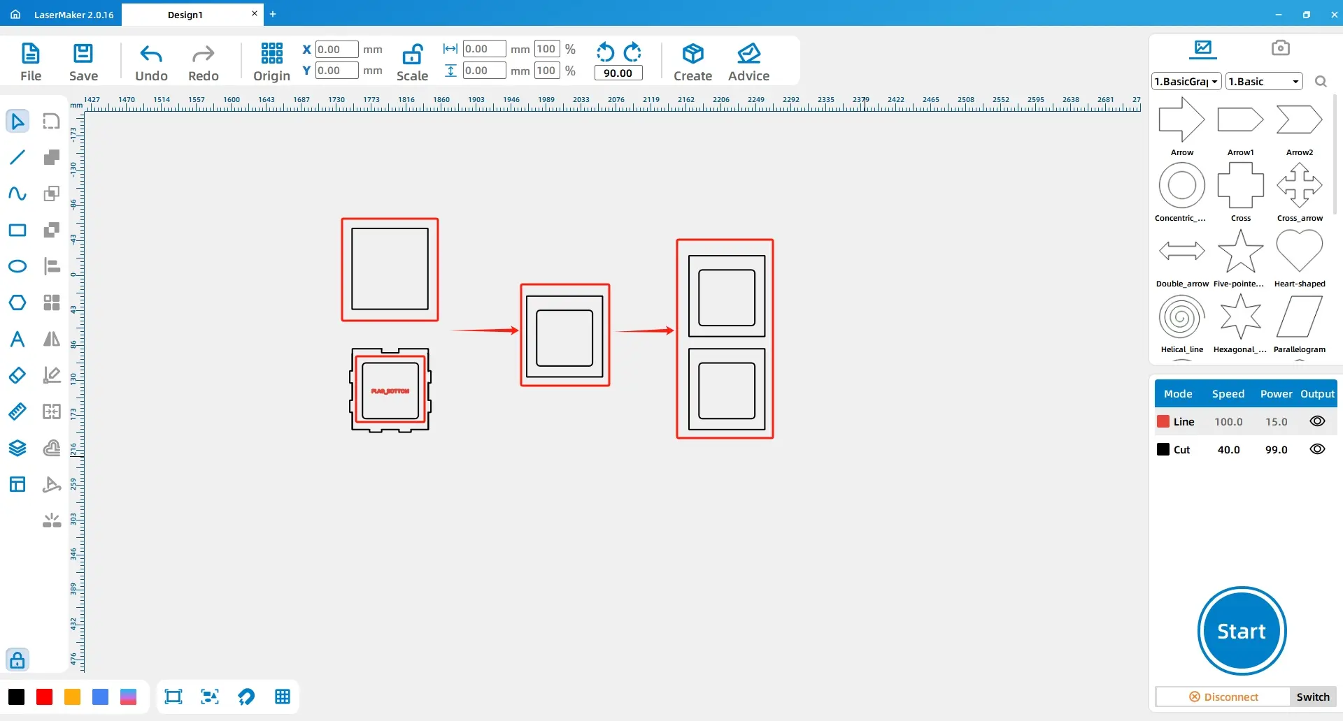
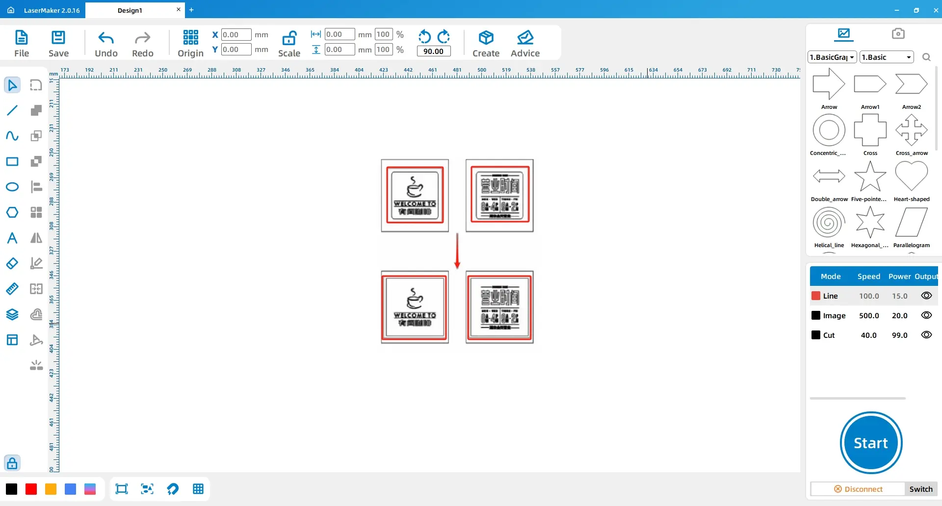
Use the Rectangle tool to draw Rectangle 1 with dimensions of 93 mm × 100 mm. Duplicate the small rectangle from inside the lower cover and move it to the centre of Rectangle 1. Then duplicate and paste Rectangle 1 and the small rectangle as shown in the reference.
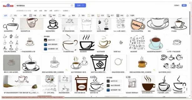
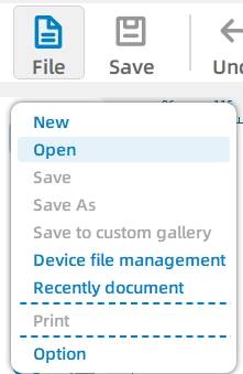
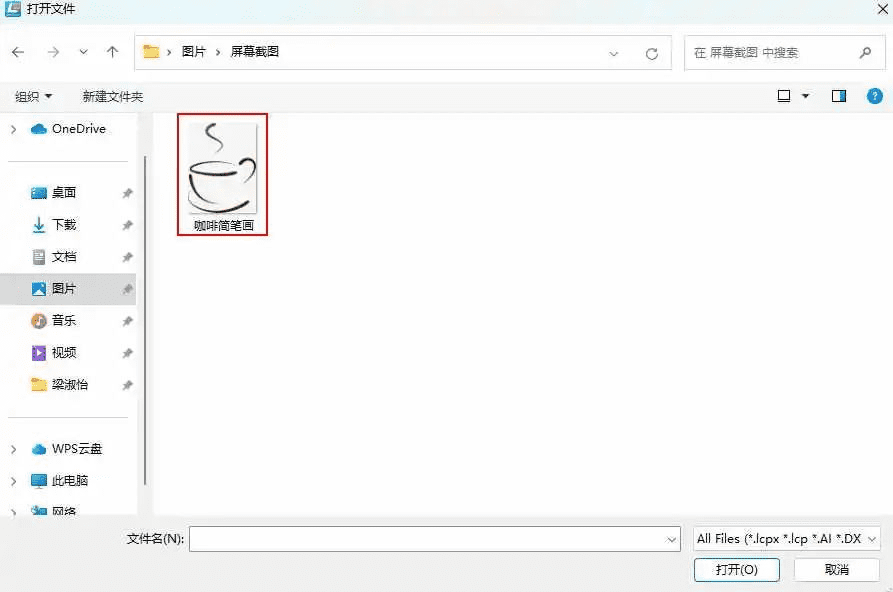
Prepare a simple coffee drawing. In the source workflow, students search for a coffee line drawing, save the image, then open it in the design software. Teachers may also provide an approved image for classroom use.
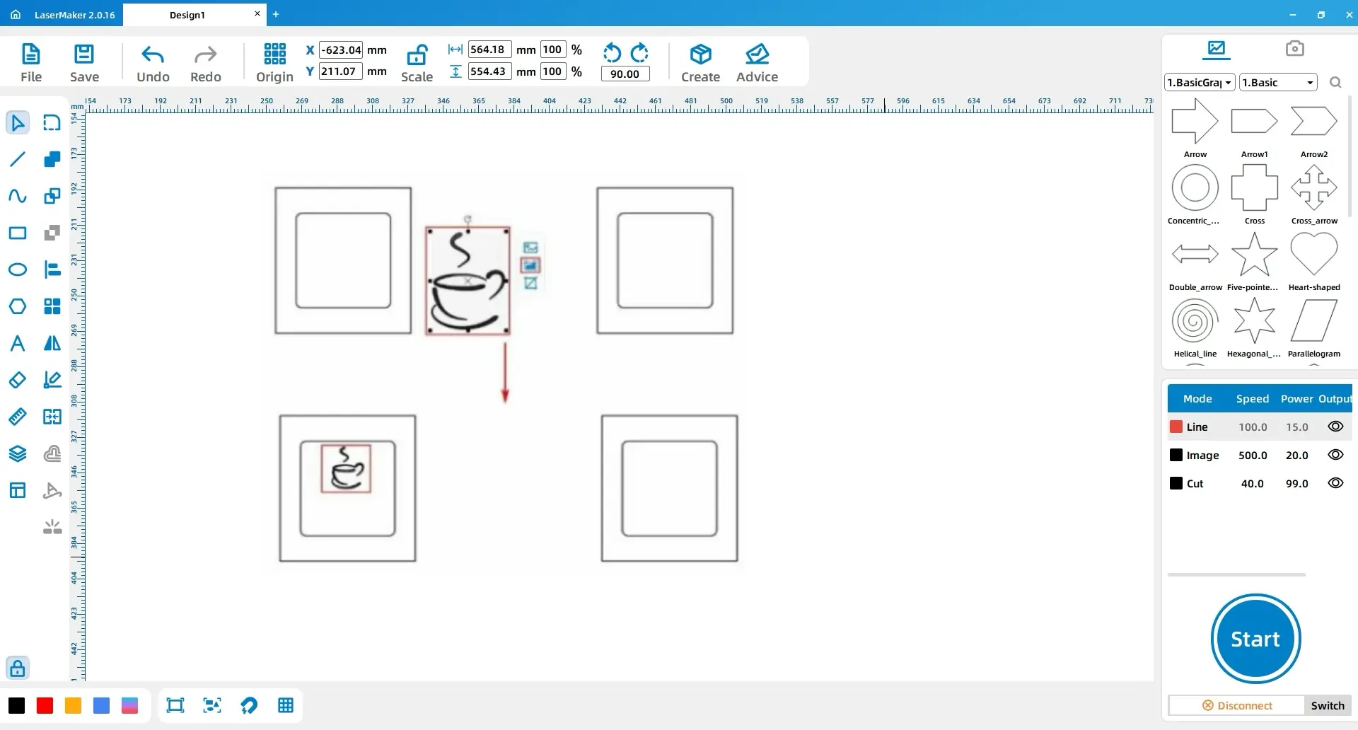
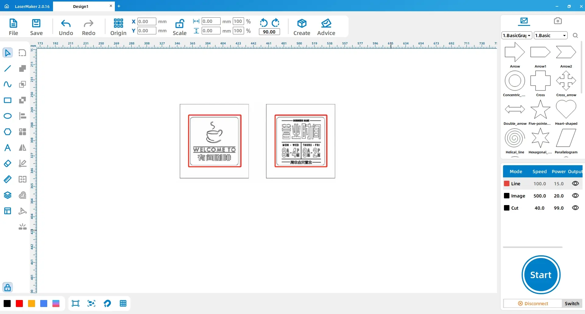
Select the coffee image, use Contour Tracing to create the outlines, adjust the size, and move it inside the left rectangle. Then use the Rectangle and Font tools to add preferred text and lines inside the small rectangle.
Delete the two small temporary rectangles. Draw two 80 mm × 80 mm rectangles and place them in the middle of the two large rectangles.
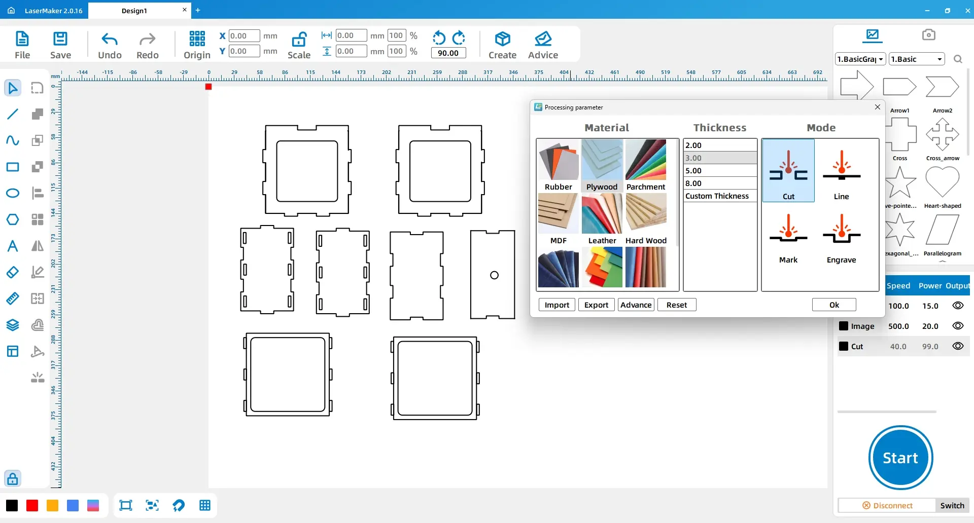
For the square frame, double-click the black layer and set the material, thickness, and process to basswood, 3 mm, and cutting.
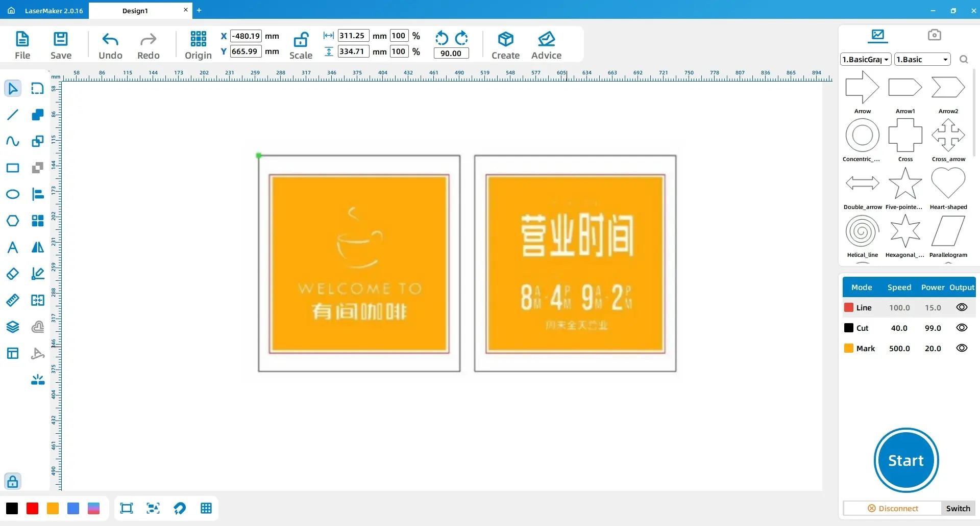
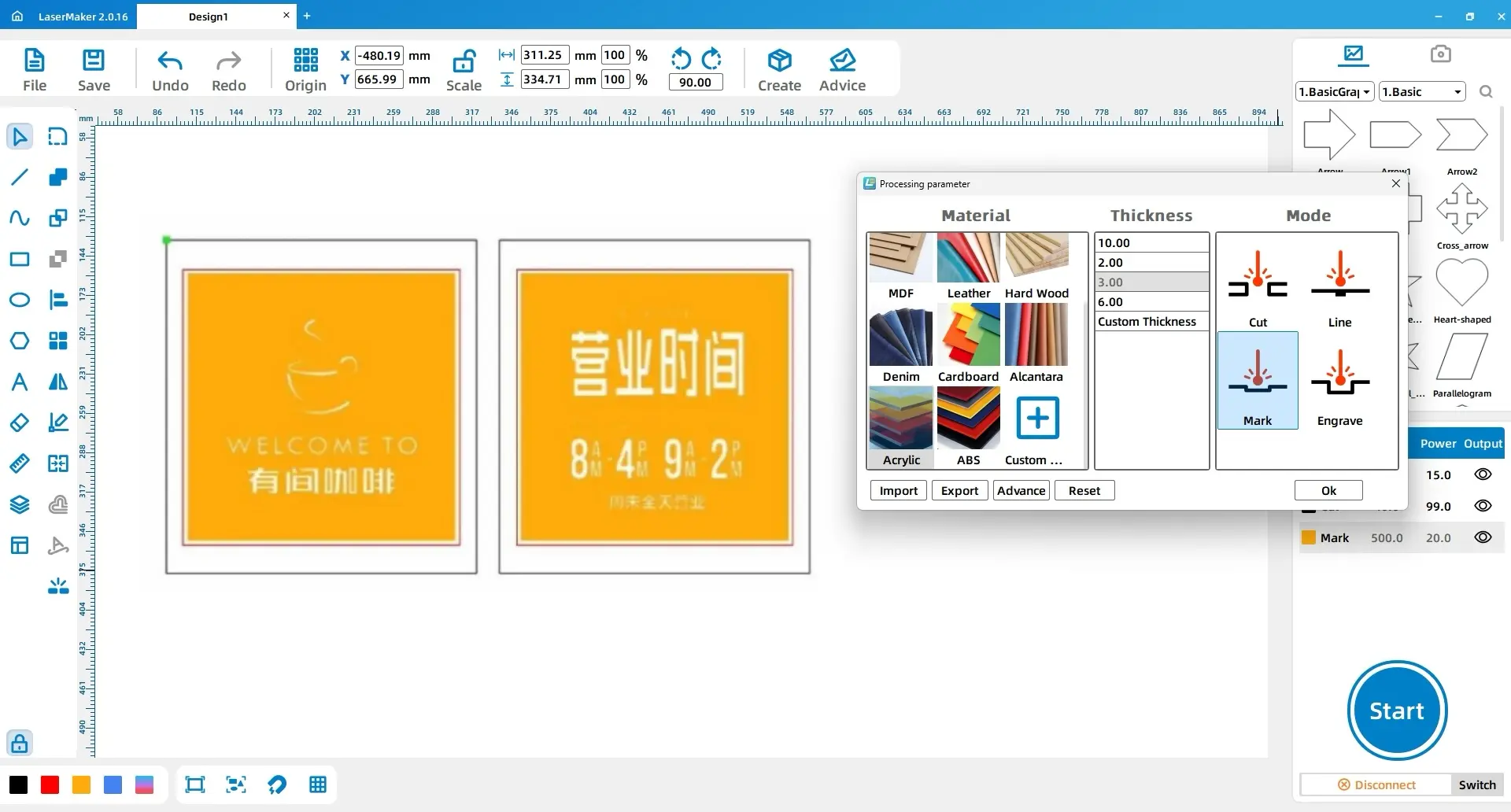
For the acrylic pattern, select all patterns except the two large rectangles and change them to the yellow layer. Set the yellow layer to acrylic, 3 mm, engraving. Set the black layer to acrylic, 3 mm, cutting.
| Part | Layer | Material | Thickness | Process |
|---|---|---|---|---|
| Square frame | Black | Basswood | 3 mm | Cutting |
| Acrylic pattern details | Yellow | Acrylic | 3 mm | Engraving |
| Acrylic outer rectangles | Black | Acrylic | 3 mm | Cutting |
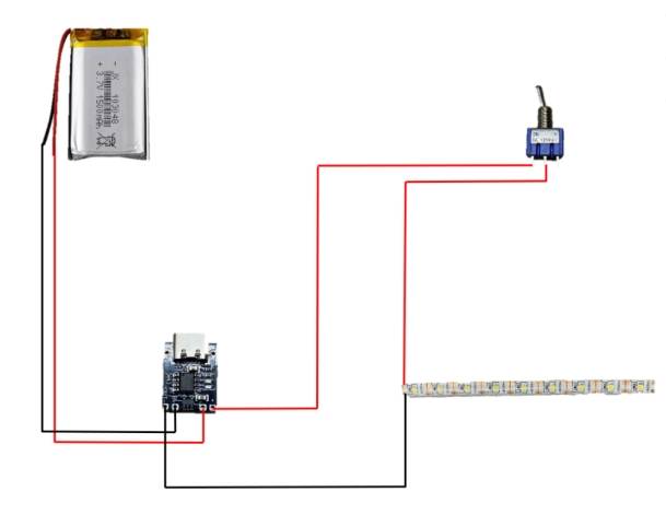
Connect the rocker switch, LED light strip, charging board, lithium-ion battery, and wires according to the circuit reference. Because this step involves a soldering iron, it should be completed carefully under teacher supervision.
Safety reminder: Check polarity, insulation, solder joints, and switch placement before powering the circuit. If the light strip does not work, turn off the power before inspecting the wiring.
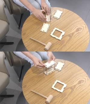
Assemble the left and right covers with the two smaller front and back covers first. Then assemble the bottom cover, followed by the top cover. Finally, assemble the two larger front and back covers.
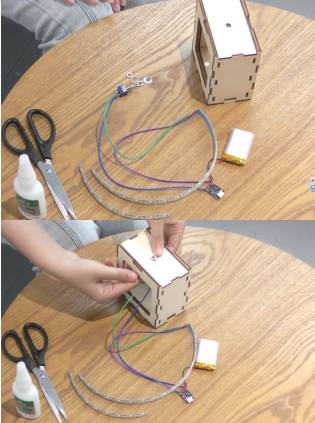
At the switch location, place a nut and gasket through the circular hole in the top cover. Screw in another nut and gasket to secure the switch. Apply glue inside the square frame and fix the wiring components in place. This combines the circuit and the outer frame.
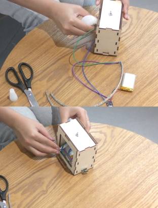
Insert the two acrylic patterns into the square frame to complete the assembly.
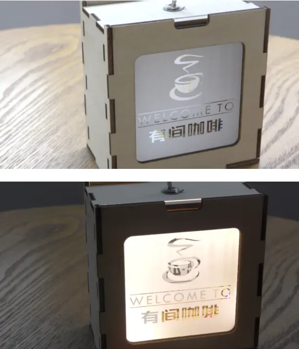
The finished ambient light combines a laser-cut basswood frame, engraved acrylic panels, LED lighting, and an internal circuit. Students can compare how the light looks when different acrylic patterns, text designs, or frame details are used.
Students can redesign the acrylic panels with a different theme, such as a bedroom night light, café sign, exhibition display, or holiday decoration. They can also experiment with different line art, text layouts, or frame details to create a new lighting style.
For schools and beginner STEAM labs with supervised electronics activities, this project can be completed on a classroom laser cutter such as the Thunder Laser Bolt Series.
Talk To Our Experts Now!
Please leave your contact information so that we can serve you better.
TAKE THE NEXT STEP WITH THUNDER LASER

 Stable & Consistent MachinesUnlimited ApplicationRobust After-sales SupportFactory Direct Supply