


How to Resize a Laser Cutting Template for Any Material Thickness LaserMaker & LightBurn
 2026-07-30
WHAT ARE YOU LOOKING FOR?
Search Across Products, Blog Posts, Support Content, And Resources.

How to Resize a Laser Cutting Template for Any Material Thickness LaserMaker & LightBurn
2026-07-30

You downloaded a laser cut box, organizer, stand, or 3D model, but the file was designed for 3 mm material and your actual sheet measures 3.2 mm, 4 mm, or 6 mm. The slots no longer fit, the tabs feel too tight, or the assembled project becomes loose and unstable.
There are two main ways to adapt the file. You can adjust only the slots, tabs, and joint dimensions when the final product size must remain unchanged. You can also scale the entire design when a proportional change in the final product size is acceptable.
The best method depends on the joint type, the software you use, and whether the project includes hardware or fixed dimensions. Material thickness is also only part of the equation. Kerf, manufacturing tolerances, coatings, and the required type of fit can all affect the finished assembly.
This guide explains how to choose the right resizing method, adjust laser cut files in LightBurn and LaserMaker, use the material thickness scaling formula, and verify the result with a test cut.
Quick Answer: The fastest way to resize a laser cut file for a different material thickness is to use a dedicated tool when your software provides one.
LightBurn: Use Resize Slots in Selection to adjust slot depth, slot width, or tab height while keeping the overall project dimensions unchanged.
LaserMaker: Use the Thickness-Based Scaling Tool to quickly scale the complete design according to the original and new material thicknesses.
If your software does not include a dedicated thickness adjustment tool, scale the complete design with this formula: New Material Thickness ÷ Original Material Thickness × 100%. You can also manually adjust slots, tabs, and joints with node editing. Always measure the actual material and run a small test cut before processing the complete project.
Use the following table to determine which method is most suitable for your project.
| Your Goal | Recommended Method | Does the Final Size Change? |
|---|---|---|
| Adapt slots and tabs while keeping the product size unchanged | LightBurn Resize Slots or manual joint editing | No |
| Quickly adapt a complete design to another material thickness | LaserMaker Thickness-Based Scaling Tool | Yes |
| Resize the file in software without a dedicated slot tool | Proportional scaling formula | Yes |
| Preserve screw holes, bearings, magnets, or other fixed-size features | Manual joint editing | No |
| Enlarge the finished product while continuing to use the same material thickness | Scale the design, then restore the slot and tab dimensions | Yes |
| Adjust internal cross-slots or unusual joint geometry | Manual editing and a fit test | Usually no |
Choose a resizing method based on whether the final product dimensions can change.
For most projects, dedicated joint resizing provides better dimensional control. Proportional scaling is faster, but it changes every part of the file, including the finished product dimensions, holes, engravings, and decorative details.
A sheet sold as 3 mm plywood may measure 2.8 mm, 3.1 mm, or another value depending on the manufacturer, material composition, humidity, surface coating, and production tolerance.
Always measure the actual sheet with digital calipers before adjusting the file.
For example, a sheet labeled as 3 mm may produce these measurements:
A practical starting value would be approximately 3.15 mm. A small joint test is still required before cutting the full project.
Material thickness and laser kerf affect a joint in different ways. Treat them as separate variables when resizing a laser cutting template.
Material thickness determines the basic dimensions of many slots, tabs, grooves, and receiving joints.
For example, an internal cross-slot must be wide enough to receive the thickness of the intersecting panel.
Kerf is the width of material removed by the laser beam during cutting. It varies according to material type, material thickness, laser source, lens and focus, power, speed, air assist, material density, and coating.
When the laser follows the center of a vector line, it removes material from both sides of that line. As a result, external parts may become slightly smaller, while internal slots and holes may become slightly larger.
Kerf compensation shifts the cutting path to account for this removed material. It should be tested for the exact material and cutting settings being used. For general parameter adjustment, see the laser parameter setting guide for beginners.
The correct joint size also depends on the desired fit.
| Fit Type | Typical Use |
|---|---|
| Loose fit | Removable panels or frequently disassembled projects |
| Slip fit | Easy hand assembly with limited movement |
| Press fit | Friction-based assembly without glue |
| Glue fit | Small clearance left for adhesive |
| Interference fit | Very tight assembly requiring controlled force |
The right slot size depends on material thickness, kerf, and the type of fit required.
There is no universal slot width that works for every 3 mm sheet. Measure the material, test the kerf, and cut a small fit sample before running the complete design.
LightBurn includes a dedicated Resize Slots in Selection tool that can automatically identify and adjust slots or tabs based on the original and new material thicknesses.
This method is ideal when you need to adapt the joints to a different sheet thickness while keeping the overall dimensions of the project unchanged.
Before using the tool, measure both the actual material thickness and the existing joint dimensions in the file. A design labeled for 3 mm material may already include clearance or kerf compensation, so its slots or tabs may not measure exactly 3 mm.
Apply the changes and run a small test cut.

| Option | What It Adjusts | Typical Use |
|---|---|---|
| Slot Depth | How far the slot extends inward | Edge slots, panel joints, and joints where depth follows material thickness |
| Slot Width | The slot opening width | Internal slots, cross-slots, dividers, and receiving joints |
| Tab Height | How far the tab extends outward | Finger joints, box tabs, edge tabs, and interlocking panels |
LightBurn may have difficulty identifying grouped objects, rounded slot corners, enclosed internal slots, irregular joint geometry, or vector paths containing unnecessary nodes. If the required joints are not detected correctly, use manual node editing instead.
For more LightBurn tips and workflow guidance, you can also visit the official LightBurn Guide.
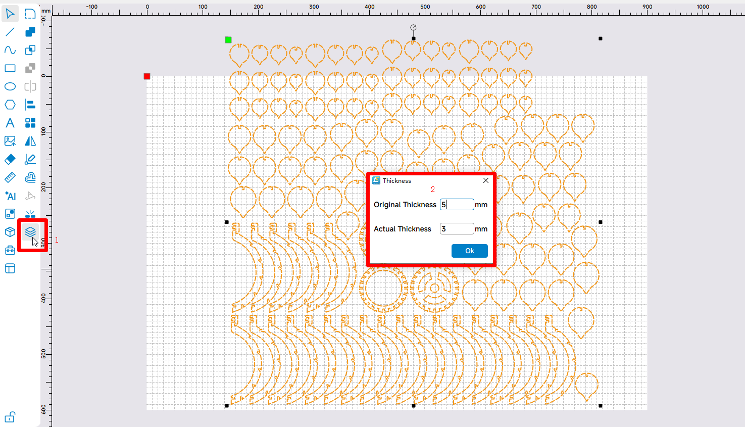
For those who prefer a faster automated approach, LaserMaker offers a Thickness-Based Scaling Tool to update a project for a different material thickness.
This method is useful for medium-sized projects or when the design contains multiple slots, tabs, and finger joints that would take too long to adjust manually.
LaserMaker can scale vector designs and also supports open shapes and engraving elements. This means engraved text, decorative patterns, open paths, holes, and the outside dimensions may also change.
Important: Thickness-Based Scaling scales the entire file. Check the final dimensions, hardware holes, text, engravings, and decorative elements before cutting.
Use a joint-specific method when the project contains:
In these cases, scaling the full design may solve the slot fit while creating problems elsewhere.
This method works in any laser software or vector design software that allows proportional scaling. Instead of adjusting each slot or tab individually, you can resize the entire design based on the ratio between your actual material thickness and the original design thickness.
This is useful for simple projects or when the design does not have complex press-fit joints.
Formula: Scale Percentage = New Material Thickness ÷ Original Material Thickness × 100%
Original design thickness: 3.00 mm
Measured material thickness: 3.18 mm
Calculation:
Scale the complete design to 106%.
A project originally measuring 200 mm wide would become:
The slots and tabs increase proportionally, but the complete product also becomes 6% larger.
The scaling formula assumes the original design was correctly sized for its stated material thickness.
If the original file includes an unknown fit allowance or kerf compensation, proportional scaling may preserve that allowance proportionally instead of producing the exact fit you need. A test cut remains necessary.
Manual editing provides the greatest control and is often the safest option when the final dimensions must remain unchanged.
You manually measure the actual material thickness, calculate the difference from the original design, and adjust each slot, tab, and finger joint accordingly. This method is useful for small projects, critical parts, or files where only the joint sizes should change.
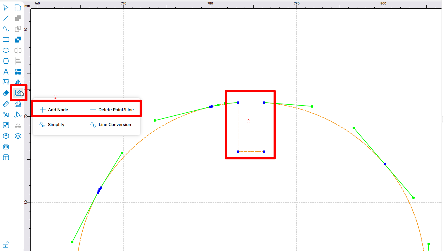
The required adjustment depends on the joint type.
Cross-slots are commonly used in dividers, tray inserts, display stands, 3D puzzles, and interlocking sculptures.
The slot width usually follows the thickness of the intersecting panel. The slot depth is generally determined by the amount of overlap or the location where the panels cross. It does not automatically equal the material thickness.
Tab height describes how far a tab extends beyond the edge of a panel.
In many box and corner joints, the tab height corresponds to the thickness of the adjoining panel. Changing the material thickness may require changing the tab height.
Slot depth describes how far a slot extends into a panel.
For edge joints, the slot depth may correspond to the material thickness. Adjusting it can preserve the outside dimensions of the assembled object.
A groove or dado receives the edge of another panel.
Its width should be adjusted to suit the actual thickness of the inserted panel, along with the required fit tolerance and kerf compensation.
For finger-joint boxes, the fingers extend through or across the thickness of the adjacent panel. Their height may need to change when a different sheet thickness is used.
Finger width and finger count usually remain unchanged unless the entire product is being redesigned or scaled.
Keep the outside geometry unchanged when the project must fit a shelf, enclosure, machine, packaging insert, or another existing object.
Finger width is measured along the panel edge. It affects joint distribution, appearance, and strength.
Changing material thickness does not automatically require changing the number or width of the fingers.
Patterns, ventilation graphics, ornaments, illustrations, and decorative openings usually have no direct relationship with material thickness.
Logos, text, photos, line art, and engraving patterns can usually remain at their original size.
Review minimum line widths and text size when the complete project is scaled down.
Screw holes, magnet pockets, bearing holes, dowel holes, hinge cutouts, and electronic component openings should remain matched to the hardware.
Mounting points and alignment marks should remain fixed when they connect to existing equipment or external parts.
| Mistake | Why It Causes Problems | Better Approach |
|---|---|---|
| Using the nominal thickness | A sheet labeled as 3 mm may not measure exactly 3 mm. | Use digital calipers before editing the file. |
| Treating kerf and material thickness as the same adjustment | Material thickness defines joint geometry, while kerf accounts for material removed by the beam. | Handle them as separate variables. |
| Scaling only one axis | Changing width without changing height distorts the entire project. | Lock the aspect ratio when using proportional scaling. |
| Scaling hardware features | Full-design scaling changes screw holes, magnets, bearings, and component openings. | Check hardware features individually. |
| Editing tab width instead of tab height | Finger width runs along the panel edge, while tab height extends outward from the panel. | Adjust the dimension that actually follows material thickness. |
| Changing cross-slot depth instead of width | For an internal divider, the slot width typically receives the thickness of the intersecting sheet. | Adjust slot width when the receiving panel thickness changes. |
| Ignoring existing clearance | The original designer may already have added clearance or kerf compensation. | Measure the actual vector geometry before entering the old material thickness. |
| Cutting the full project without testing | A complete failed assembly wastes more time and material. | Run a small slot-and-tab test first. |
Most resizing errors happen when material thickness, kerf, and fixed-size features are treated as one problem.
A test cut should use the same material sheet, laser machine, lens, focus, cutting speed, power, air assist, kerf compensation, and grain direction or material orientation as the final project.
Create several slots with slightly different widths around the measured material thickness.
For material measuring 3.15 mm, a test may include:
Label each slot directly in the file. Cut the sample, test the fit, and record the best result.
A good test file can also include tabs with different dimensions so you can compare loose, slip, glue, and press fits.
For materials with visible grain or directional structure, test both the X and Y orientations. Plywood, cardboard, and some laser beams may produce slightly different results depending on the cutting direction.
For reliable results, follow this sequence:
The correct way to resize a laser cut file depends on what must remain fixed.
Use LightBurn’s Resize Slots tool or manual joint editing when the finished product dimensions need to stay unchanged. Use LaserMaker’s Thickness-Based Scaling Tool or the proportional scaling formula when the entire design can become larger or smaller.
Accurate results begin with the measured material thickness and finish with a real test cut. Kerf, material tolerance, surface coatings, and fit requirements can all affect the final assembly, even when the vector dimensions appear correct.
LaserMaker helps simplify laser design, material adjustment, file preparation, and production workflows. Explore LaserMaker to create or adapt laser cut box files, press-fit projects, slot-and-tab designs, and other laser cutting templates for your actual material thickness.
Need Help Preparing Laser Cutting Files?
Use LaserMaker and Thunder Laser material settings to prepare laser cut box files, press-fit templates, slot-and-tab projects, and production-ready cutting files for your actual material thickness.
Explore LaserMaker View CO₂ Laser SettingsTalk To Our Experts Now!
Please leave your contact information so that we can serve you better.
WOOD LASER ENGRAVING
& CUTTING FAQS
The new Bolt Series has been upgraded with faster engraving speeds (up to 2000 mm/s), higher RF power options (up to 80W), larger working areas, improved Z-axis height, and Standard dual-air assist. We also added a recessed tray design for larger rotary objects and included new accessories such as a conical nozzle.
The new Bolt Series has been upgraded with faster engraving speeds (up to 2000 mm/s), higher RF power options (up to 80W), larger working areas, improved Z-axis height, and Standard dual-air assist. We also added a recessed tray design for larger rotary objects and included new accessories such as a conical nozzle.
The new Bolt Series has been upgraded with faster engraving speeds (up to 2000 mm/s), higher RF power options (up to 80W), larger working areas, improved Z-axis height, and Standard dual-air assist. We also added a recessed tray design for larger rotary objects and included new accessories such as a conical nozzle.
The new Bolt Series has been upgraded with faster engraving speeds (up to 2000 mm/s), higher RF power options (up to 80W), larger working areas, improved Z-axis height, and Standard dual-air assist. We also added a recessed tray design for larger rotary objects and included new accessories such as a conical nozzle.
The new Bolt Series has been upgraded with faster engraving speeds (up to 2000 mm/s), higher RF power options (up to 80W), larger working areas, improved Z-axis height, and Standard dual-air assist. We also added a recessed tray design for larger rotary objects and included new accessories such as a conical nozzle.
NEED HELP FINDING THE RIGHT SOLUTION?
Talk to our team for machine recommendations, application advice, and support based on your needs.


 Stable & Consistent MachinesUnlimited ApplicationsRobust After-sales SupportFactory Direct Supply


