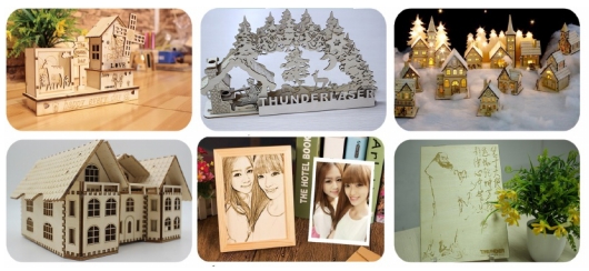
ThunderLaser STEAM Education Student
Course (Thematic)
1. What is the main role of passenger aircraft?
2. What are the main structures of an airliner?
3. If you had to design your idea of an airliner, how would you design?
1.Make a single piece of outline airliner
(1) Sketch the passenger plane in your mind.
(Tip: Draw a side view of the airliner)
(2) Use the mobile APP “Scanning Almighty King” to scan the painted train and import it into the laser software LasrMaker.
(3) Click “Picture – Crop” on the menu bar above the software to crop out the blank part.
(4) Click “Picture- Outline” to sketch out the outline.
(5)In the layer parameter area on the right of the software, select no output picture, box out the inner outline and delete it, leaving the outer outline, and finally select output picture.
(6) Double-click the layer parameter area on the right side of the software to set the parameters of the layer.
(7) After completing the above Settings, import it into the machine for processing, and the single piece of train will be made successfully!
2. Make a complete version of airliner
(1) Draw the wheels (called landing gear) of the passenger plane 3 and make several small wooden rings using the function of array replication. Finally draw a circle with a diameter of 3mm on the wheel (called landing gear) part of the passenger plane.
(The wheel size is a circle with a diameter of 13mm.)
(2) Use the “weld” function to design 2 plates for welding.
(Welding plate size is 20*15mm, welding card size is 10*3mm)
Draw the tail and main wings of the airliner
(3) Draw a 60*15mm rectangle for splicing the tail section of the fighter jet.
(4) Draw a 20 by 120mm rectangle and use the “Draw Bessel Curves and lines” feature to draw the wings of the fighter.
(In the process of drawing, first click the left mouse button to trace, and then drag to the appropriate place to trace, at this time do not immediately release the left mouse button, long press the left mouse button and drag, you can draw the arc, depict the appropriate arc to release the mouse, you can press the right mouse button to end the painting.)
(5) Copy and paste the wing for mirror processing, and use the “welding” function to weld the wing to the rectangle, the other side of the wing the same welding operation.
(6) Draw the corresponding bayonet and place it according to the position shown.
(The dimensions are①10*2.7 ②37 *2.7③15*2.7)
(7)Mirror the image to complete the final design.
After the design of all parts is completed, the design drawing is imported into the machine for processing, and the assembly is carried out after the machine processing is completed.
(8) Splice the welded plate on the cut fighter and use hot melt glue or white latex to glue it firmly.
(9) Attach the wheels to the front and rear of the aircraft using small sticks and wooden rings to act as landing gear for the aircraft.
(10) Use small sticks and small wooden rings to attach the wheels to the front and rear of the warplane.
(two for the rear wheel and one for the front wheel)
3. Machine processing
The design files saved in the above demonstration are respectively imported into the laser cutting machine for processing. Tip: remember to adjust the focal length before processing to avoid the situation of impenetrable cutting.
4. Works upgrade
Install remote control
(1) Use glue to attach the remote control receiver plate to the vertical tail of the passenger aircraft.
(2)Glue the two small motors on both sides of the main wing of the passenger plane and install the propeller on the rotating shaft of the two small motors. (The small motors on both sides should be symmetrical)
(Tip: After the installation is completed, manually turn the propeller to check whether it will touch the plane, if it touches the plane, a small board can be placed under the small motor.)
(3)Take out the battery box and the switch device, connect the black wire (negative electrode) on the battery box and the receiving board with electrical tape, and connect the red line (positive electrode) to the switch.
(Tip: the positions of the two red lines are connected)
(4) Connect the BL line (green line and white line) on the receiving board to the small motor on the right, install the battery, and press the right button on the remote control after opening the switch to check whether the small motor can rotate.
(5) Connect the BF line (blue line and yellow line) on the receiving board to the small motor on the left, also turn on the switch, press the left button on the remote control to test whether the small motor can rotate.
Installation notes:
1. The direction of rotation of the propellers on both sides should be opposite, that is, the rotation direction of the left propeller is clockwise, and the rotation direction of the right propeller is counterclockwise.
2. The B arc of the spiral blade leans inward (bends inward).
3. After installation, install the 18650 lithium battery and turn on the switch. Use the remote control to check whether the propeller can drive the aircraft forward.
If the aircraft can move forward, the following two situations will occur:
Press the upper button of the left and right keys of the remote control, and the plane moves forward (Normal).
Press the lower keys of the left and right keys of the remote control, and the plane is driving backward, then the wires of the small motor are removed, and the positions are exchanged to reconnect.
(Tip: The green and white wires are still connected to the right motor, and the blue and yellow wires are still connected to the left motor.)
If the propeller does not move the aircraft forward, the following installation problems occur:
1. Electrical wiring is incorrectly installed.
2. Propeller installation error, B arc outward.
3. The rotation of the propellers on both sides is not opposite, that is, the rotation in the same direction.
If the plane can travel forward normally, then the remote-controlled aircraft is done!
Evaluation item | Self-evaluation | Peer evaluation |
Creativity (30 points) |
|
|
1. Through the production process of this lesson, what is the basic structure of a train?
2. What are the differences between a train and a car that we can learn from the making process of this lesson?
3. How can you make your train run faster?
Firm (30 points) |
|
|
Beauty (20 points) |
|
|
Attitude (20 points) |
|
|
Total (100 points) |
|
|
ThunderLaser STEAM Education Course (Thematic)
Exercise
Guide the students to make a airliner based on the teaching lesson in Lesson 1
* Exercise students’ thinking ability and practical ability.
* Consolidate software machine operation exercises.
* Improve students’ ability to learn independently.
* Make an airliner .
* Consolidate software and machine operation exercises.
* Make an airliner .
* Please prepare relevant consumables, accessories and tools according to the attached table and the actual number of students.
* Ensure that students have the latest version of LaserMaker laser editing software installed on their computers.
* Please prepare the relevant presentation props in advance according to the PPT.
→ Guide students to know the basic structure of a passenger plane by asking questions:
(1)Think about it, what is the main role of the airliner ?
Manned and cargo
(2) What are the main structures of an airliner?
Wings, fuselage, tail, landing gear, power plant, etc…
(3)If you were asked to design an airplane in your mind, how would you design it?
→ Play the Magic Brush Maliang – Airliner Inventor Teaching Video.
Guide the students to review the main content of lesson 1 and teach the new operating points
Make a single outline airliner demonstration
(1)Use the mobile APP “Scan Almighty King” to scan the finished drawing and import it into the laser editing software LaserMaker. First, click “Picture-Crop” on the menu bar above the software to crop out the blank part, and then click “Picture -outline” to describe the outline of the image.
(2)In the layer parameter area on the right of the software, select No output image, box out the inner outline and delete it, leave the outer outline, and then select output image.
(3) Double-click the layer parameter area on the right side of the software to set the parameters of the layer.
Make a stereoscopic airliner demonstration
(1)Draw the wheels of the passenger plane (called landing gear) and make several small wooden pieces with the function of array replication.
(wheel size is 13mm diameter circle.)
(2)Design 2 pieces of welded plates using the function of “welding”.
(Weld plate size is 20*15mm, weld card size is 10*3mm)
(3)Draw a circle with a diameter of 3mm on the wheel (called landing gear) part of the passenger jet.
Draw the wings and tail of the airliner
(4) Draw a 60*15mm rectangle for splicing the tail section of the airliner.
(5) Draw a 20*120mm rectangle and use the “Draw Bessel curves and lines” function to draw the wings of the fighter aircraft.
(In the process of drawing, first click the left mouse button to trace, and then drag to the appropriate place to trace, at this time do not immediately release the left mouse button, long press the left mouse button and drag, you can draw the arc, depict the appropriate arc to release the mouse, you can press the right mouse button to end the painting.)
(6) Copy and paste the wing for mirror processing, and use the “welding” function to weld the wing to the rectangle, the other side of the wing the same welding operation.
(7) Draw the corresponding bayonet, and place it according to the position shown, and mirror the image.
(The dimensions are ①10*2.7 ②37 *2.7 ③15*2.7)
After the design of all parts is completed, the design drawing is imported into the machine for processing.
(8) Splice the welded plate on the cut fighter and use hot melt glue or white latex to glue it firmly.
(9) Attach the big and small wheels to the front and rear of the aircraft using small sticks and small wooden rings.
(Two for the front wheels and one for the rear wheels)
The design files saved in the above demonstration are respectively imported into the laser cutting machine for processing.
Tip: remember to adjust the focal length before processing to avoid the situation of impenetrable cutting.
(1)Hand-drawing: Organize to issue pen and paper to each student for hand-drawing creation within 10 minutes. Arrange at least two assistants to help check whether the edge of hand-drawn works is clearly closed, and use mobile phones to collect and import them into their own computers.
(2)Software design: Guide students to complete the complete design, assist in naming the design file with student number and name and transfer it to the matching computer of the laser cutting machine.
(3)Machine processing: Guide students to complete machine processing steps according to the order of completion of the design.
(4) Assembly: Distribute tools in groups and guide students to assemble their works independently.
Installing a remote control
(1) Use glue to attach the remote control receiver plate to the vertical tail of the passenger aircraft.
(2) Glue the two small motors on both sides of the main wing of the passenger plane and install the propeller on the rotating shaft of the two small motors. (The small motors on both sides should be symmetrical)
(Tip: After the installation is completed, manually turn the propeller to check whether it will touch the plane, if it touches the plane, a small board can be placed under the small motor.)
(3) Take out the battery box and the switching device, connect the black line (negative electrode) on the battery box and the receiving board with electrical tape, and connect the red line (positive electrode) to the switch.
(Tip: the positions of the two red lines are connected)
(4) Connect the EBL line (green line and white line) of the receiving board to the small motor on the right, install the battery, and press the right button on the remote control after opening the switch to check whether the small motor can rotate.
(5) Connect the BF line (blue line and yellow line) on the receiving board to the small motor on the left, also turn on the switch, press the left button on the remote control to test whether the small motor can rotate.
Installation notes:
1. The direction of rotation of the propellers on both sides should be opposite, that is, the rotation direction of the left propeller is clockwise, and the rotation direction of the right propeller is counterclockwise.
2. The B arc of the spiral blade leans inward (bends inward).
3. After installation, install the 18650 lithium battery and turn on the switch. Use the remote control to check whether the propeller can drive the aircraft forward.
If the aircraft can move forward, the following two situations will occur:
Press the upper button of the left and right keys of the remote control, and the plane moves forward (Normal).
Press the lower keys of the left and right keys of the remote control, and the plane is driving backward, then the wires of the small motor are removed, and the positions are exchanged to reconnect.
(Tip: The green and white wires are still connected to the right motor, and the blue and yellow wires are still connected to the left motor.)
If the propeller does not move the aircraft forward, the following installation problems occur:
1. Electrical wiring is incorrectly installed.
2. Propeller installation error, B arc outward.
3. The rotation of the propellers on both sides is not opposite, that is, the rotation in the same direction.
If the plane can travel forward normally, then the remote-controlled aircraft is done!
Questions:
1. Through the production process of this lesson, what is the basic structure of a airliner?
Fuselage, wing, tail (divided into vertical tail and horizontal tail), power plant, take-off and landing device, etc.
2.What is the function of each basic structure of an airliner, respectively?
Fuselage: for carrying people and things
Main wing: Generates lift, but can also house ammunition silos and fuel tanks inside the wings, and can store landing gear in flight. Tail wing: controls the lift and deflection of the aircraft, and ensures smooth take-off and landing.
Power unit: to ensure the normal operation of the aircraft engine
Take-off and landing device: to ensure the flexible movement of the aircraft on the ground, reduce the impact and turbulence of the aircraft landing, taxi brake deceleration.
Reviews:
Teachers can make reasonable comments and rewards based on the works produced by students.