


Remote-Control Collector Car Laser Cutting Project for STEAM Classrooms
 2024-07-26
WHAT ARE YOU LOOKING FOR?
Search Across Products, Blog Posts, Support Content, And Resources.

Remote-Control Collector Car Laser Cutting Project for STEAM Classrooms
2024-07-26

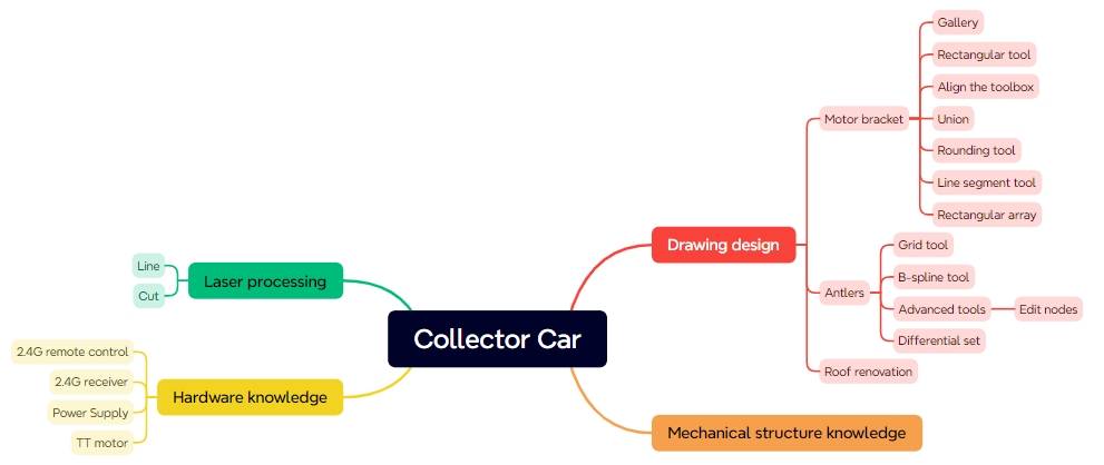
In this STEAM robotics and mechanism project, students upgrade a basic remote-control vehicle body into a collector car using LaserMaker. The lesson connects robot chassis modification, TT motor mounting, mortise-and-tenon bracket design, antler-shaped hook modeling, B-spline curves, node editing, wiring, laser cutting, and hands-on assembly.
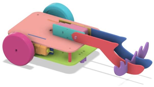
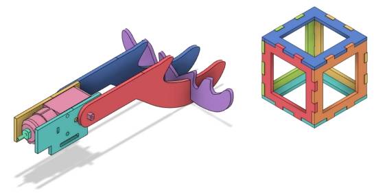
This project builds on the previously designed basic chassis. Students focus on the collection mechanism: a TT motor drives an antler-shaped hook that rotates to catch hollow cube-shaped energy stones.
| Item | Details |
|---|---|
| Project | Remote-control collector car with antler hook mechanism |
| Software | LaserMaker |
| Main Skills | Rectangle Tool, Union Tool, Difference Tool, Rounded Corner Tool, Line Tool, Rectangular Array, TT Motor graphics, B-Spline Tool, Edit Nodes, alignment, outlining, cutting, wiring, and assembly |
| Suggested Materials | Base chassis, TT motor, and basswood plywood, 40 cm × 60 cm × 3 mm |
| Classroom Fit | Robotics and mechanism projects, robot attachment design, collection mechanisms, remote-control vehicles, maker education, laser cutting, and creative engineering challenges |
Students will design a collector mechanism for a remote-control vehicle. They will create a motor bracket, a bracket locking pin, forward-facing antlers, a horizontal antler, and a modified chassis roof panel with motor-bracket mortises and a wiring hole. After laser cutting, they will assemble the mechanism and test whether the antler hook can collect target objects.
For teachers: Use this project to connect robot attachments, motor-driven rotation, curved vector drawing, joint design, and iterative mechanism testing.
For students: Use the activity to upgrade a basic robot chassis into a task-based collector vehicle.
For makerspaces: Use it as a practical add-on project after learners complete a basic remote-control chassis.
Modify a basic robot chassis so it can carry a new collection mechanism.
Design a TT motor bracket with a through-tenon and locking pin for secure installation.
Use B-spline curves and node editing to create custom antler-shaped hook parts.
Create cross-tenon features so vertical and horizontal antlers can connect more securely.
Laser cut, wire, assemble, and test a motor-driven collection mechanism on a remote-control vehicle.
Design thinking: Turn a task requirement into a practical vehicle attachment that can catch and carry target objects.
Computational thinking: Use dimensions, spacing, arrays, rotation, alignment, and node adjustment to create accurate digital parts.
Engineering thinking: Consider motor support, hook stability, joint fit, wiring access, rotating clearance, and collection reliability.
Students should test powered vehicle attachments under teacher or lab supervisor guidance. Keep hands, loose wires, and small parts away from the rotating antler hook and moving vehicle during operation.
Many robots use the same mobile chassis with different task attachments. A base vehicle can become a collector, dumper, crane, or other task-based robot by changing the mechanism mounted on top.
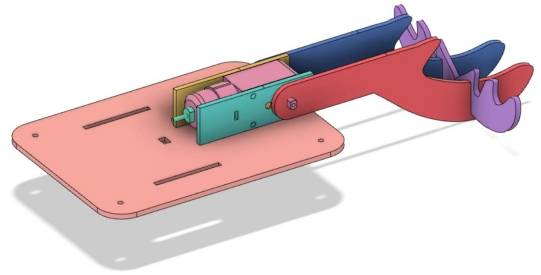
In this lesson, the collector car is designed to gather hollow cube-shaped energy stones. A TT motor rotates an antler-shaped hook so the vehicle can latch onto the stones during movement.
The base chassis is reused from the previous vehicle body project. The new laser-cut work focuses mainly on the motor bracket, pins, antler parts, and modified chassis roof panel.
| No. | Item | Quantity |
|---|---|---|
| 1 | Base chassis | 1 |
| 2 | TT motor | 1 |
| 3 | Basswood plywood, 40 cm × 60 cm × 3 mm | 1 |
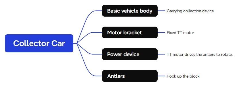
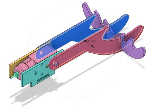
The collector car is organized into four main functional groups.
| Part No. | Part Name | Quantity | Function |
|---|---|---|---|
| 1 | Base Chassis | 1 | Carries the collection mechanism |
| 2 | Motor Bracket | 1 | Secures the TT motor |
| 3 | Power Unit | 1 | Drives the rotation of the antler hook |
| 4 | Deer Antler Hook | 1 | Hooks onto the energy stones |
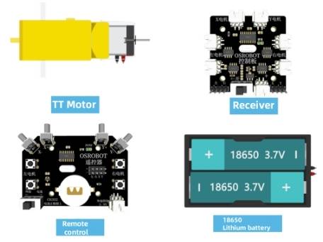
The collection mechanism uses a TT motor as its power source, so the first task is to design a bracket that can hold the motor securely on the chassis roof panel.
Open LaserMaker, select the TT Motor graphic from the Open-Source Robotics library, and drag it onto the canvas. Group the motor graphic and check its size. In the source workflow, the TT motor graphic is 70.13 mm wide and 22.30 mm high, so the motor bracket body is set to 72 mm wide and 22.30 mm high for clearance.
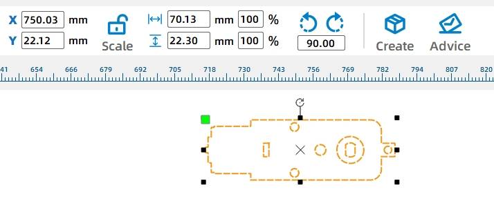
Draw a 72 mm by 22.30 mm rectangle for the main body of the motor bracket. Center-align the TT motor graphic with this rectangle so the mounting positions match the motor.
To attach the bracket to the chassis, add a tenon and a through-tenon slot. Draw a 40 mm by 9 mm rectangle for the bracket tenon, align it with the bottom edge of the bracket body, and center it vertically.
Draw a 20 mm by 3 mm rectangle as the through-tenon mortise. Center-align it inside the bracket tenon. Then select the bracket body and tenon and use Union to merge them into the motor bracket shape.
To improve cutting efficiency and appearance, ungroup the TT motor graphic and keep only the required mounting information. Delete redundant outlines, holes, and circles. Since the bracket design uses two pieces, duplicate the bracket.
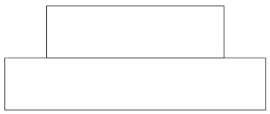
The motor bracket uses a through-tenon and a pin to lock the bracket onto the chassis. The pin head needs to be slightly larger than the mortise. In the source workflow, the pin head width is set to 20.4 mm.
Draw a 20.4 mm by 6 mm rectangle for the pin head and a 30 mm by 6 mm rectangle for the pin handle. Align the handle under the pin head and center them horizontally. Apply a 2 mm rounded corner to the pin head so it is easier to insert.
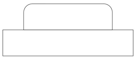
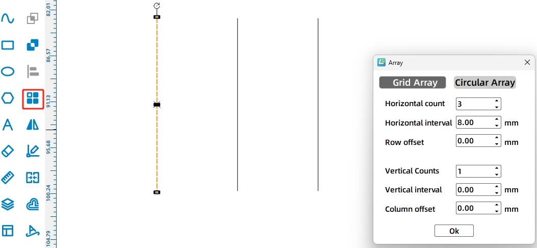
To reduce tightness, add three vertical slits to the pin head. Use the Line Tool to draw a 6 mm vertical line, then use Rectangular Array with 3 horizontal lines and 8 mm spacing. Align the slit lines on the pin head, merge the pin head and handle with Union, and duplicate the finished pin so there are two pins.

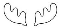
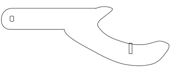
The antler-shaped hook is designed to catch the energy stones. The forward-facing antler includes a handle with a TT motor shaft hole and a curved antler shape.
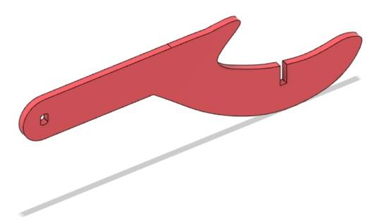
Turn on the Grid Tool. Draw a 90 mm by 20 mm rectangle for the antler handle. From the Open-Source Robot section, select the TT Motor Hole graphic and place it on the left side of the rectangle, aligning it vertically.
Use the B-Spline Tool to draw the curved hand-shaped antler. Click points on the canvas to create the approximate shape, then close the curve. Use Edit Nodes to adjust node positions and tangents until the curve is smoother.
Tool Tip: B-spline and Bézier-style curves are useful for drawing organic shapes such as antlers, hooks, handles, and decorative parts. Editing nodes helps students improve both appearance and function.


Turn off the Grid Tool. Select the handle rectangle and the curved antler shape, then use Union to merge them. Apply a 10 mm rounded corner to the two left-side corners so the antler is less likely to hit the base chassis during rotation.

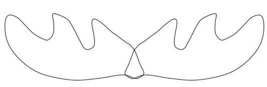
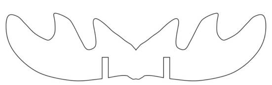
A single forward-facing antler can hook the energy stone, but it may not provide enough stability. Adding a horizontal antler between the two forward-facing antlers improves the structure, helps prevent the stone from falling toward the motor, and keeps the collection action more reliable.
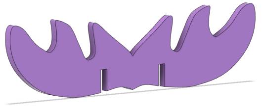
Use the B-Spline Tool to draw one antler shape, then use Edit Nodes to smooth the curve. In the source workflow, the antler is set to 64 mm wide and 31 mm high. Duplicate it, align the copy horizontally with the original, and use Union to merge the two shapes into one horizontal antler.


To stabilize the antler structure, add cross-tenon features so the forward-facing antlers and horizontal antler can interlock.
Draw a 2.85 mm by 10 mm rectangle as one mortise. Use Rectangular Array with 2 horizontal copies and 25.5 mm horizontal spacing to create two mortises for the horizontal antler. Move them to suitable positions, align them, and use Difference to create the mortises.

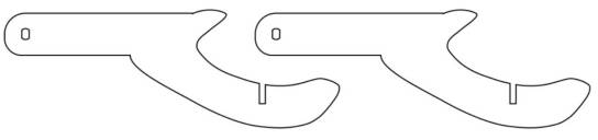
Draw a 2.85 mm by 10 mm rectangle on the forward-facing antler and use Difference to create the matching mortise. Duplicate the finished forward-facing antler so the final structure includes two forward-facing antlers and one horizontal antler.
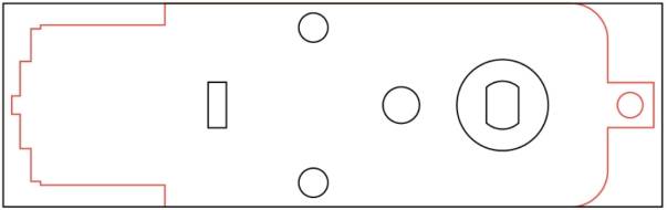
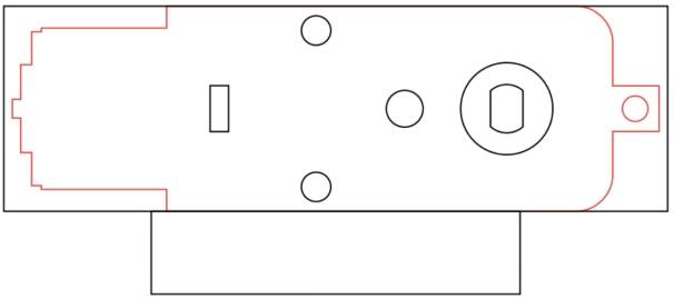
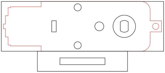
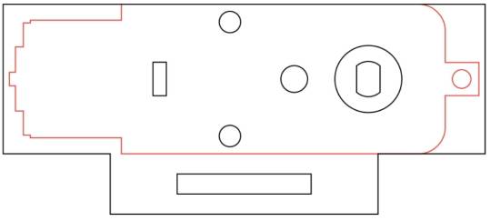
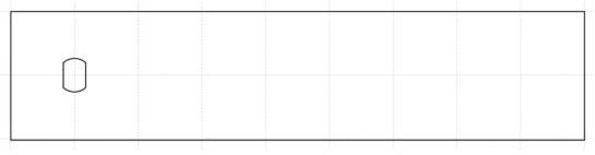
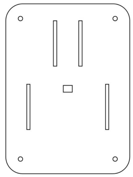
The new motor bracket needs to be mounted on the base chassis roof panel, so students should add bracket mortises and a wiring hole to the roof panel.
The motor bracket tenon is 40 mm wide and 9 mm high. Since the basswood plywood is 3 mm thick, draw a 40 mm by 3 mm rectangle for the matching mortise. Because the TT motor thickness is 19.5 mm, use a rectangular array to create the matching pair of mortises.
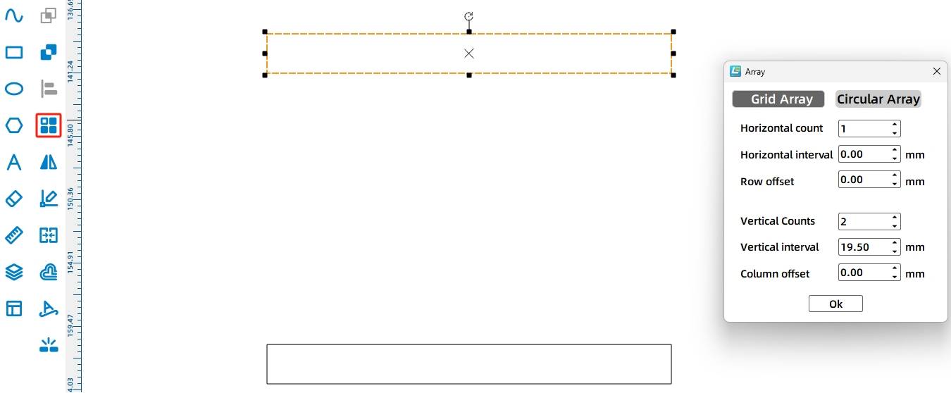
Rotate the mortises by 90 degrees and place them near the upper edge of the roof panel. Center-align them vertically, then increase the Y-coordinate by 15 mm to move the mortises downward into the final position.
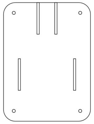
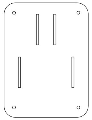
Because the antler-driving TT motor sits above the chassis, add a wiring hole so the motor can connect to the OSROBOT control board. Draw an 8 mm by 6 mm rectangle and center-align it on the top panel.
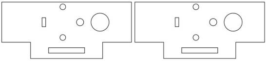
After the motor brackets, pins, antlers, and modified roof panel are complete, arrange the final layout for laser processing.

After completing the drawing, set the laser processing parameters. The source workflow uses outlining for red-layer objects and cutting for black-layer objects.
Outlining: Double-click the red block in the processing parameter area. Select Basswood Plywood as the material, choose Outlining, and set the cutting depth to 0.10.
Cutting: Double-click the black block in the processing parameter area. Select Basswood Plywood as the material, choose Cutting, and set the cutting depth to 3.00.
Turn on the laser cutting machine and laser switch. When the Start Manufacturing button becomes ready, upload the drawing to the laser cutting machine and start cutting from the machine panel.
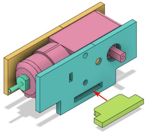
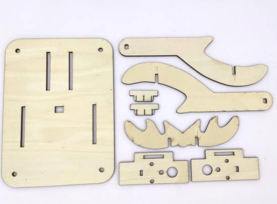
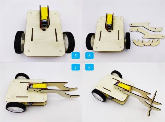
After laser cutting, identify the new mechanism parts before assembly.
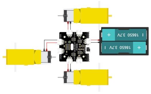
For the collector vehicle to work properly, connect the TT motor that drives the antler rotation to the control board according to the wiring diagram.
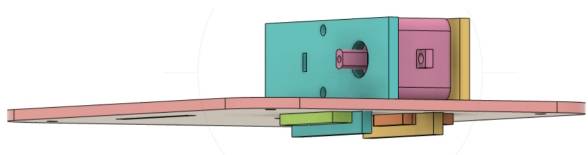
First, locate the new base chassis roof panel and the motor bracket parts. Assemble the TT motor and motor bracket, install the motor bracket onto the roof panel, and secure the bracket with a pin.
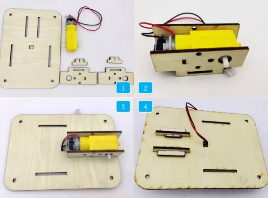
Remove the original base chassis roof panel, connect the antler-driving TT motor to the control board, and install the new roof panel. Then locate the antler parts, attach the vertical antler to the TT motor, and secure the horizontal antler onto the vertical antler.
Check whether the motor bracket fits securely into the roof-panel mortises.
Confirm that the locking pin holds the motor bracket in place without being too tight.
Test whether the antler hook rotates without hitting the base chassis.
Review whether the horizontal antler improves stability and helps prevent the collected object from sliding toward the motor.
Drive the vehicle slowly during testing and observe whether the hook can collect the target energy stones reliably.
After design, laser processing, wiring, and assembly, students complete a remote-control collector car. The project gives students practical experience with robot chassis modification, motorized attachments, B-spline drawing, node editing, mortise-and-tenon mounting, and functional mechanism design.
The collector car uses a simple rotating antler hook to collect energy stones. As an extension challenge, students can redesign the hook shape, change the antler angle, adjust motor speed, or create a different collection tool for another type of object.
Students can also compare how different hook shapes affect collection success, stability, and ease of releasing the object after it has been collected.
This project is suitable for classroom laser cutters that support cutting and outlining of sheet materials for small robotics and mechanism projects. For schools, makerspaces, and beginner STEAM labs, projects like collector cars, robot attachments, motor brackets, and laser-cut mechanism upgrades can be completed with a classroom laser cutter such as the Thunder Laser Bolt Series.
Teachers can choose the machine and material setup based on classroom space, material thickness, electronic components, moving-part clearance, and learning goals. The same LaserMaker workflow can also be adapted for other CO2 laser machines when students move on to more advanced robot attachments or task-based competition vehicles.
Talk To Our Experts Now!
Please leave your contact information so that we can serve you better.
NEED HELP FINDING THE RIGHT SOLUTION?
Talk to our team for machine recommendations, application advice, and support based on your needs.

 Stable & Consistent MachinesUnlimited ApplicationRobust After-sales SupportFactory Direct Supply


