


Remote-Control Basic Vehicle Body Laser Cutting Project for STEAM Classrooms
 2024-07-26
WHAT ARE YOU LOOKING FOR?
Search Across Products, Blog Posts, Support Content, And Resources.

Remote-Control Basic Vehicle Body Laser Cutting Project for STEAM Classrooms
2024-07-26

In this STEAM robotics project, students design and build a universal remote-control vehicle body using LaserMaker. The lesson connects laser-cut chassis plates, TT motor mounting, mortise-and-tenon sizing, caster wheel placement, receiver and battery mounting, wiring, and hands-on robot chassis assembly.
This project helps students create a reusable base vehicle body that can support later robot designs, such as a collection vehicle, dumper, or crane. The main engineering focus is accurate mortise-and-tenon fitting between the motor mounting plates and the top and bottom vehicle plates.
| Item | Details |
|---|---|
| Project | Remote-control basic vehicle body / universal robot chassis |
| Software | LaserMaker |
| Main Skills | Rectangle Tool, Rounded Corner Tool, Union Tool, Rectangular Array, TT Motor graphics, Caster Wheel graphics, control board graphics, battery placement, alignment, outlining, cutting, wiring, and assembly |
| Suggested Material | Basswood plywood, 40 cm × 60 cm × 3 mm |
| Classroom Fit | Robotics and mechanism projects, robot chassis design, motor mounting, mortise-and-tenon construction, remote-control vehicles, maker education, and laser cutting |
Students will design a basic vehicle body with two motor mounting plates, a top body plate, and a bottom body plate. They will add motor, caster wheel, receiver, and battery mounting positions, laser cut the parts, assemble the chassis, connect the circuit, and test the remote-control vehicle body.
For teachers: Use this project to introduce robot chassis design, motor placement, caster support, component layout, and accurate mortise-and-tenon fitting.
For students: Use the activity to build a reusable robot base before adding more advanced vehicle functions or competition attachments.
For makerspaces: Use it as a foundational remote-control vehicle project that prepares learners for more complex robot builds.
Design TT motor mounting plates with side tenons that fit into the chassis plates.
Create top and bottom vehicle body plates with rounded corners, mortises, and fixing holes.
Use LaserMaker library graphics for TT motors, caster wheels, control boards, and battery mounting positions.
Apply rectangular arrays, alignment tools, coordinate movement, grouping, and layer setup to create production-ready parts.
Assemble the vehicle body, install motors and electronics, wire the remote-control system, and test basic movement.
Design thinking: Create a universal chassis that can be reused for multiple robot vehicle projects.
Computational thinking: Use dimensions, spacing, arrays, coordinate offsets, and part alignment to build an accurate laser-cut layout.
Engineering thinking: Consider motor placement, caster support, battery clearance, mortise-and-tenon fit, screw locations, and chassis stability.
Students should test powered vehicles under teacher or lab supervisor guidance. Keep fingers, loose wires, and small parts away from moving wheels and motors during testing, and check all screws, nuts, and wiring before driving the chassis.
A reusable vehicle chassis is a practical starting point for many robotics projects. Instead of redesigning the base every time, students can first create a reliable body that holds motors, wheels, a caster wheel, a receiver, and a battery.
In this project, the chassis is designed for future amusement-park vehicle builds, including a collection vehicle, dumper, and crane. The same base can support different attachments once the drive structure is complete.
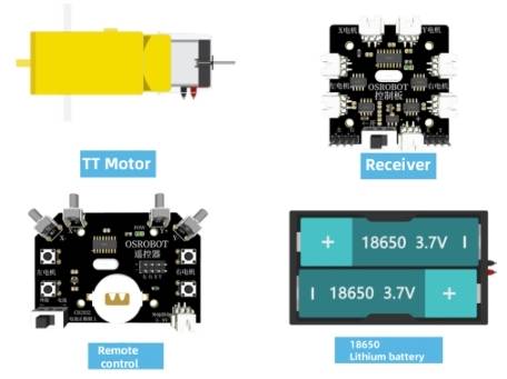
Before modeling the vehicle body, students should identify the remote-control components, motors, structural material, fasteners, and support hardware used in the project.
| Number | Name | Quantity |
|---|---|---|
| 1 | 2.4G Remote Controller with battery | 1 |
| 2 | 2.4G Receiver | 1 |
| 3 | TT Motor, 1:120 | 2 |
| 4 | 18650 Battery with cable | 1 |
| 5 | Basswood Plywood, 40 cm × 60 cm × 3 mm | 1 |
| 6 | M3/M4 screws, nuts, and nylon standoffs | Several |
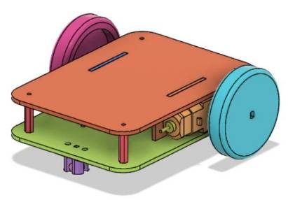
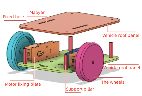
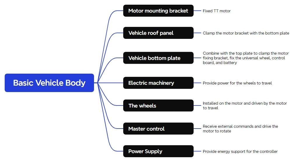
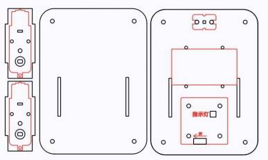
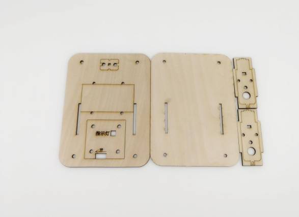
The laser-cut vehicle body is organized into three main structural parts: two motor mounting plates, one top body plate, and one bottom body plate.
| Part No. | Part Name | Quantity | Function |
|---|---|---|---|
| 1 | Motor Mounting Plate | 2 | Secures the TT motors |
| 2 | Top Body Plate | 1 | Combines with the bottom plate to sandwich the motor mounting plates |
| 3 | Bottom Body Plate | 1 | Combines with the top plate and secures the caster wheel, receiver board, and battery |
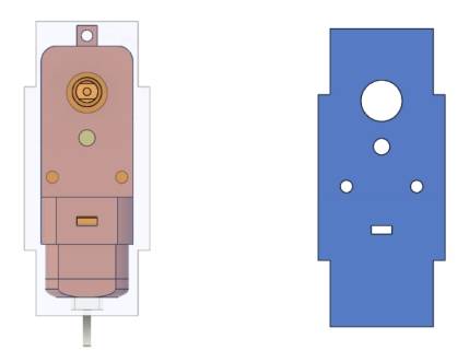
The motor mounting plates hold the two TT motors and connect to the top and bottom body plates through mortise-and-tenon joints. Start by drawing the main motor mounting plate shape, then add side tenons and motor mounting holes.
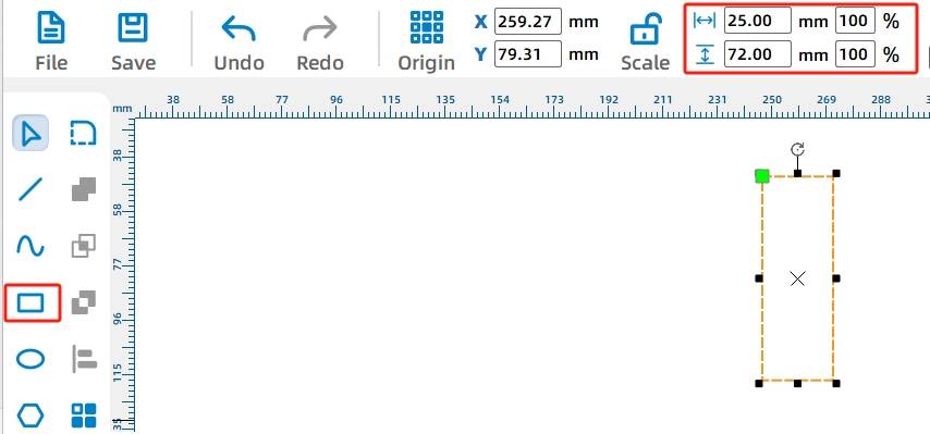
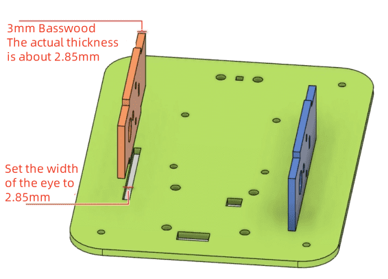
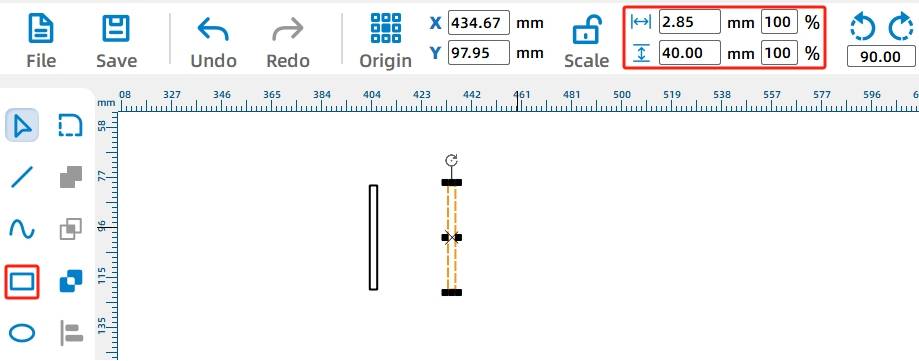
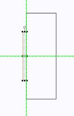
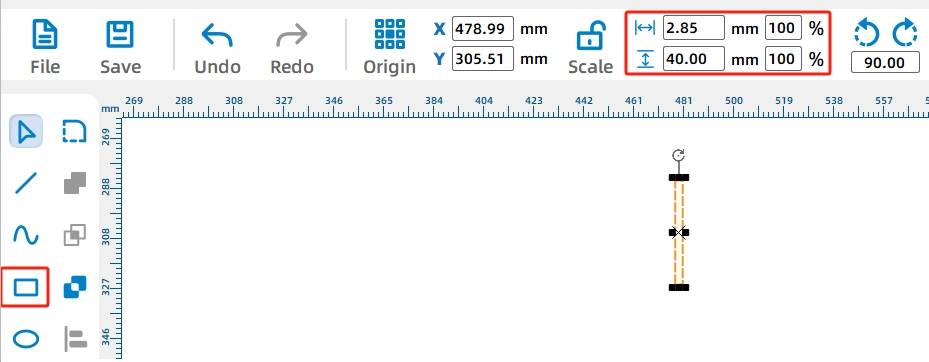
Use the Rectangle Tool to draw a 25 mm by 72 mm rectangle as the main motor mounting plate. Because the plate connects to the vehicle body through mortise-and-tenon joints, add one tenon on each side. In the source workflow, each side tenon is 2.85 mm wide and 40 mm high, based on the practical thickness of the 3 mm basswood board and laser cutting loss.
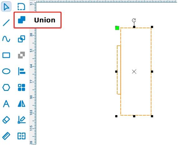
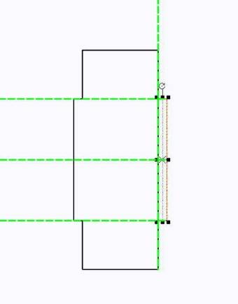
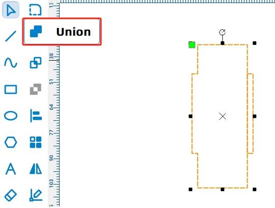
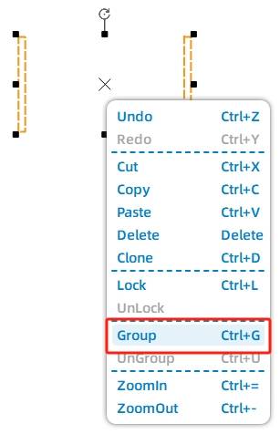
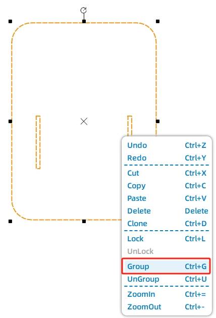
Move the first tenon to the left side of the plate, align it, and use Union to merge it with the main rectangle. Repeat the same process on the right side to complete the motor mounting plate outline.
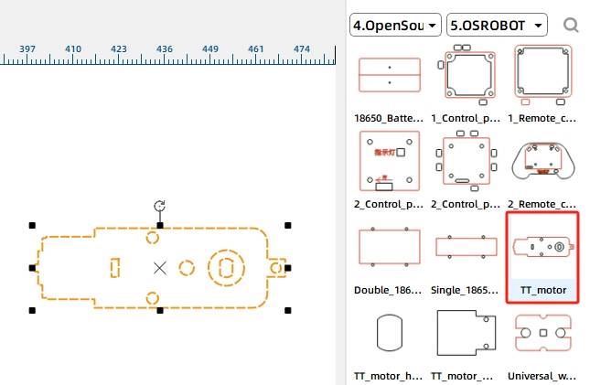
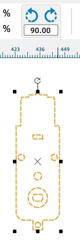
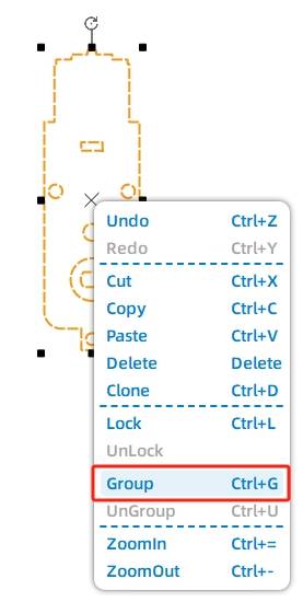
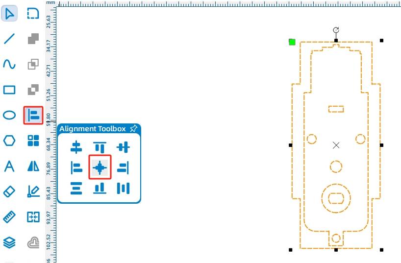
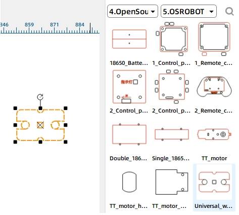
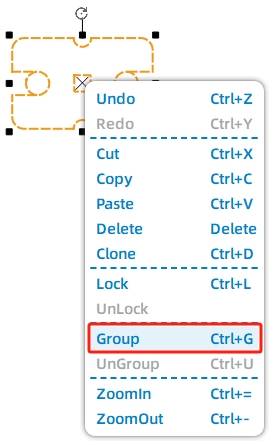
Next, add the TT motor mounting pattern. Open the LaserMaker library, locate Open-Source Robot Hardware, choose TT Motor, and drag it onto the canvas. Rotate the TT motor hole pattern by 90 degrees, group it, and center-align it with the motor mounting plate.
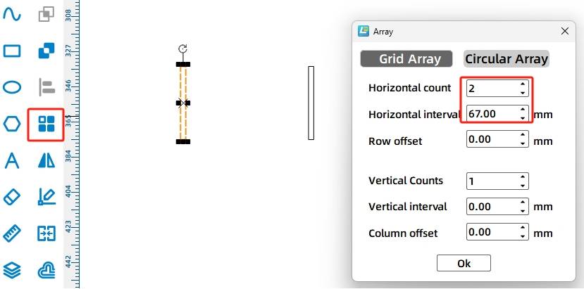
The vehicle body uses two TT motors, so it needs two motor mounting plates. Select the completed mounting plate and use Rectangular Array to create a second copy. In the source workflow, the horizontal count is 2, the horizontal spacing is 10 mm, and the vertical count is 1.
The top plate and bottom plate clamp the motor mounting plates in place. The top plate needs rounded corners, two mortises for the motor mounting plates, and four fixing holes.
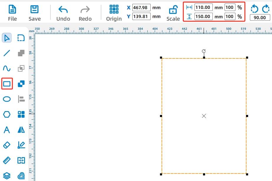
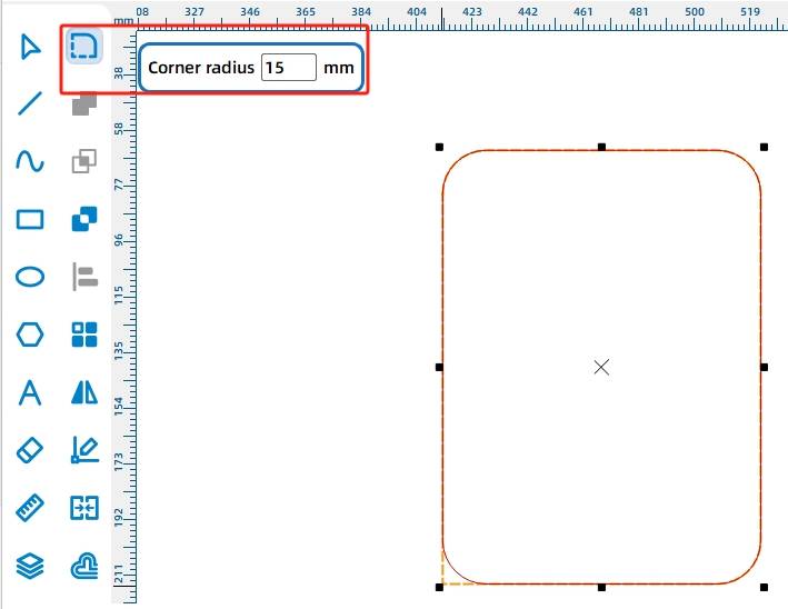
Draw a rectangle and set it to 110 mm wide and 150 mm high. Then use the Rounded Corner Tool with a 15 mm radius to round all four corners.
Add the mortises for the motor mounting plates. Draw a 2.85 mm by 40 mm rectangle as one mortise. Because a 18650 battery needs to fit between the two motor mounting plates, the source workflow sets the distance between the two mortises to 67 mm, slightly larger than the battery width.
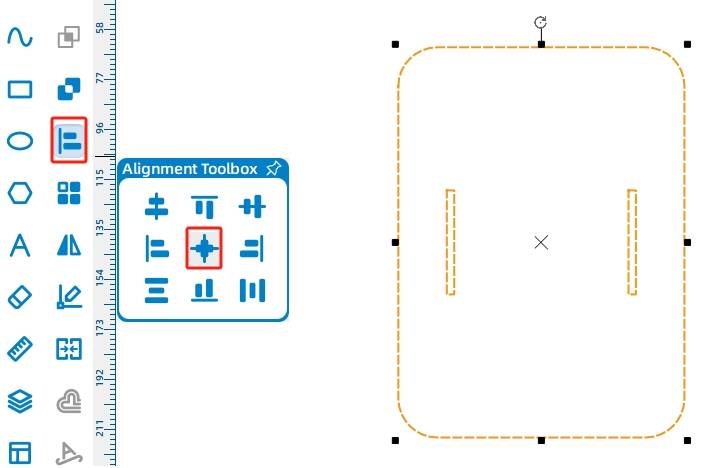
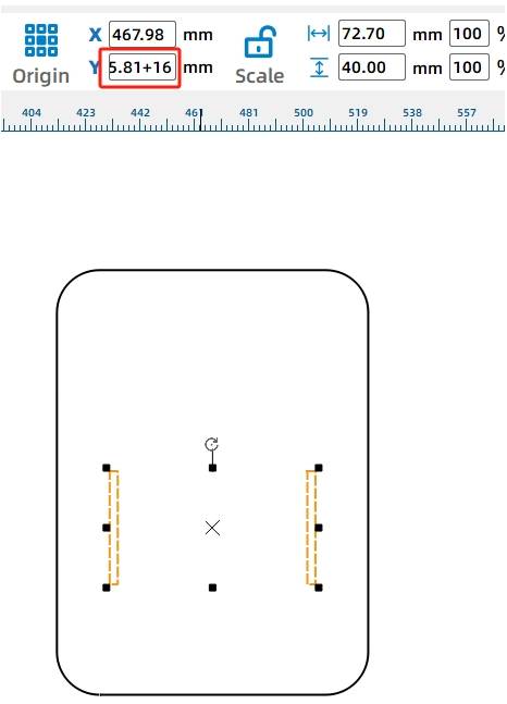
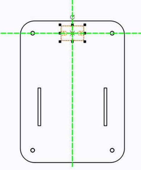
Center-align the mortises with the top plate, then move the mortises down by 16 mm so the motors sit closer to the rear of the chassis. In LaserMaker, increasing the Y-axis value moves the selected graphic downward.
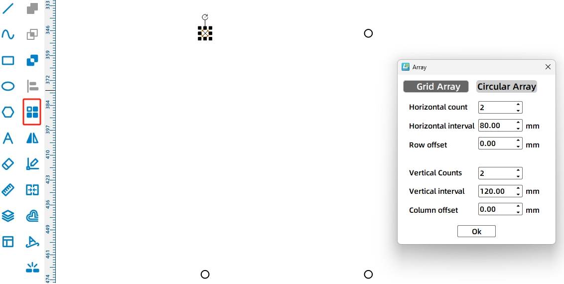
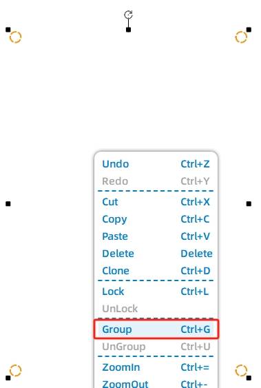
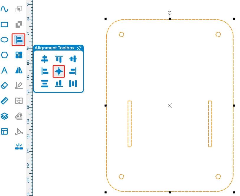
Add four 4 mm fixing holes to the chassis plate. Use Rectangular Array with 2 horizontal copies, 80 mm horizontal spacing, 2 vertical copies, and 120 mm vertical spacing. Group the holes and center-align them with the plate, without selecting the mortises.
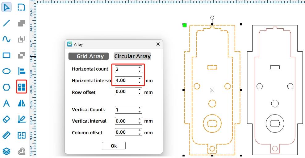
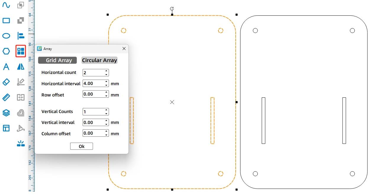
After the top plate is complete, use Rectangular Array to create the bottom plate from the top plate. In the source workflow, the horizontal count is 2 and the horizontal spacing is 4 mm.
To help the vehicle move flexibly, add a caster wheel to the bottom plate. Select the Caster Wheel graphic from the Open-Source Robot Hardware library, group the caster wheel graphic, and align it near the front of the bottom plate.
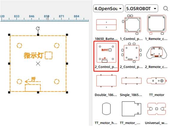
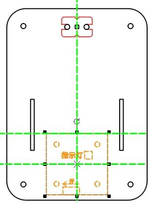
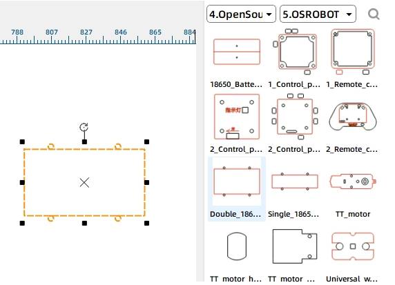
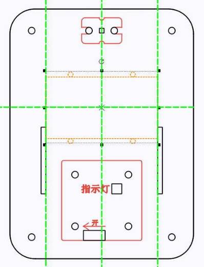
The bottom plate also needs mounting positions for the receiver board and battery. Add the 2.0 Control Board graphic from the Open-Source Robot Hardware library and place it in the square area of the chassis. Then add the Double 18650 Battery graphic and place it above the control board area.
After the motor mounting plates, top plate, and bottom plate are complete, arrange the final drawing for laser processing.
After completing the drawing design, set the laser processing parameters. The source workflow uses outlining for red-layer objects and cutting for black-layer objects.
Outlining: Double-click the red block in the processing area. Select Basswood Plywood as the material, choose Outlining, and set the processing thickness to 0.10.
Cutting: Double-click the black block in the processing area. Select Basswood Plywood as the material, choose Cutting, and set the processing thickness to 3.00.
Turn on the laser cutting machine and laser switch. When the Start Fabrication button becomes ready, upload the drawing to the laser cutting machine and start cutting from the machine panel.
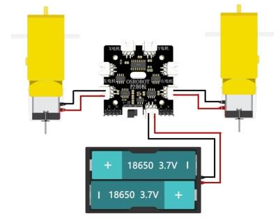
After the chassis is assembled, connect the circuit according to the wiring diagram. The receiver, battery, and two TT motors allow the vehicle body to move by remote control.
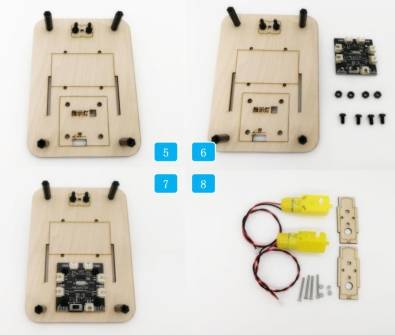
First, identify the caster wheel, chassis bottom plate, M4 screws, and nuts. Install the caster wheel onto the underside of the chassis bottom plate and tighten it with M4 nuts.
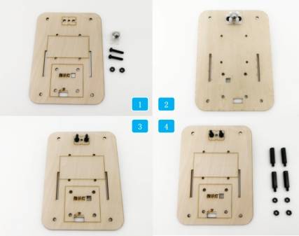
Insert the nylon standoffs into the round holes at the four corners of the chassis plate and tighten them with nuts. Then locate the receiver board, short M4 screws, and M4 nuts, and secure the receiver board to the square section of the bottom plate.
Next, locate the TT motors, motor mounting brackets, M3 screws, and M3 nuts. Fix each motor onto a motor mounting bracket. The source workflow notes that the nuts should be placed on the inside of the wood to prevent protruding screw ends from interfering with wheel installation.
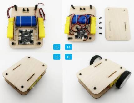
Attach the motor brackets to the chassis plate. Then secure the 18650 battery to the rectangular area of the chassis plate with cable ties.
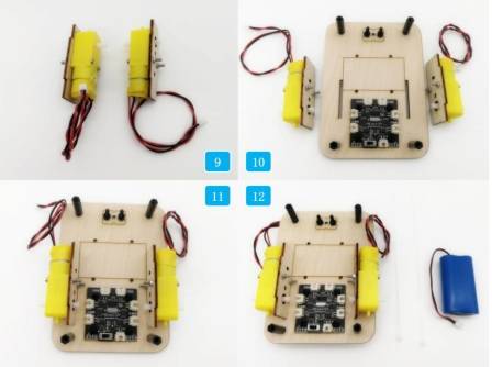
Connect the wiring according to the circuit diagram. Finally, place the chassis top plate over the bottom plate and attach it with screws. Once the top plate is installed, the basic vehicle body assembly is complete.
Check whether the motor mounting plates fit securely into the top and bottom plate mortises.
Confirm that the caster wheel is aligned and can rotate freely.
Test whether the two TT motors run correctly after wiring the receiver and battery.
Review whether the battery and receiver are fixed securely before driving the chassis.
Observe whether the chassis moves straight, turns smoothly, and remains stable during basic remote-control testing.
After design, laser processing, wiring, and assembly, students complete a remote-control basic vehicle body. The project gives students practical experience with robot chassis planning, TT motor mounting, caster wheel support, receiver and battery placement, and precise mortise-and-tenon sizing.

After completing the basic chassis, students can upgrade it with new functions, such as a collection vehicle body, dumper attachment, crane structure, or custom competition module.
For an additional engineering challenge, students can redesign the top plate, bottom plate, and motor mounting plates so the chassis can be assembled and fixed without using screws. This encourages students to explore more advanced mortise-and-tenon structures and snap-fit design ideas.
This project is suitable for classroom laser cutters that support cutting and outlining of sheet materials for small robotics and mechanism projects. For schools, makerspaces, and beginner STEAM labs, projects like robot chassis plates, motor mounting brackets, remote-control vehicle bodies, and competition vehicle bases can be completed with a classroom laser cutter such as the Thunder Laser Bolt Series.
Teachers can choose the machine and material setup based on classroom space, material thickness, electronic components, moving-part clearance, and learning goals. The same LaserMaker workflow can also be adapted for other CO2 laser machines when students move on to larger vehicle bodies or more advanced robotics projects.
Talk To Our Experts Now!
Please leave your contact information so that we can serve you better.
NEED HELP FINDING THE RIGHT SOLUTION?
Talk to our team for machine recommendations, application advice, and support based on your needs.

 Stable & Consistent MachinesUnlimited ApplicationRobust After-sales SupportFactory Direct Supply


