


Remote-Control Amusement Park Billboard Laser Cutting Project for STEAM Classrooms
 2024-07-18
WHAT ARE YOU LOOKING FOR?
Search Across Products, Blog Posts, Support Content, And Resources.

Remote-Control Amusement Park Billboard Laser Cutting Project for STEAM Classrooms
2024-07-18

In this STEAM robotics and mechanism project, students design and build a remote-control amusement park billboard using LaserMaker. The lesson connects advertising sign design, laser-cut structures, a TT motor, an anti-rotation yoke, a reciprocating sliding rod, remote-control components, wiring, and hands-on assembly.
This project helps students understand how circular motor motion can be converted into left-right reciprocating motion. Students design a billboard, support rods, a disc with eccentric holes, an anti-rotation slot, a sliding rod, spacers, and a box base that holds the moving mechanism.
| Item | Details |
|---|---|
| Project | Remote-control amusement park billboard |
| Software | LaserMaker |
| Main Skills | Rectangle Tool, Ellipse Tool, Text Tool, Rectangular Array, Rounded Corner Tool, Union Tool, grouping, alignment, X-axis movement, One-Click Fabrication, tracing, cutting, wiring, and assembly |
| Suggested Material | Basswood laminate, 40 cm × 60 cm × 3 mm |
| Classroom Fit | Robotics and mechanism projects, reciprocating motion, advertising display design, maker education, laser cutting, and remote-control structures |
Students will design a moving amusement park billboard that can slide left and right. They will create the laser-cut parts in LaserMaker, set outlining and cutting processes, assemble the anti-rotation yoke mechanism, connect the circuit, and test whether the billboard moves smoothly.
For teachers: Use this project to connect circular motion, reciprocating motion, eccentric holes, sliding slots, measurement, and laser-cut assembly.
For students: Use the activity to build a moving billboard while learning how a mechanism can turn motor rotation into back-and-forth movement.
For makerspaces: Use it as a powered display project that combines laser cutting, a TT motor, screws, a sliding rod, electronics, and remote control.
Analyze how a static billboard can be redesigned as a moving display.
Use a disc, eccentric hole, anti-rotation slot, and sliding rod to create reciprocating motion.
Create a billboard, support rods, spacers, disc, slide mechanism, and box base in LaserMaker.
Use alignment, grouping, rectangular arrays, rounding, X-axis movement, Union, and One-Click Fabrication tools accurately.
Assemble the mechanical structure, connect the receiver, battery, and TT motor, and test the moving billboard.
Design thinking: Turn a familiar public billboard into a more eye-catching moving display for an amusement park setting.
Computational thinking: Use hole spacing, slot length, eccentric distance, part dimensions, arrays, and coordinate movement to create a precise mechanism.
Engineering thinking: Consider sliding clearance, shaft spacing, motor placement, spacer thickness, screw connections, box stability, and reliable reciprocating motion.
Students should test powered mechanisms carefully under teacher or lab supervisor guidance. Keep fingers, loose wires, and small parts away from the rotating disc and sliding mechanism while the billboard is moving.
Billboards are common in bus stops, subway stations, shopping malls, supermarkets, and amusement parks. Most signs are static, but a moving billboard can attract more attention because the display changes position and draws the viewer’s eye.
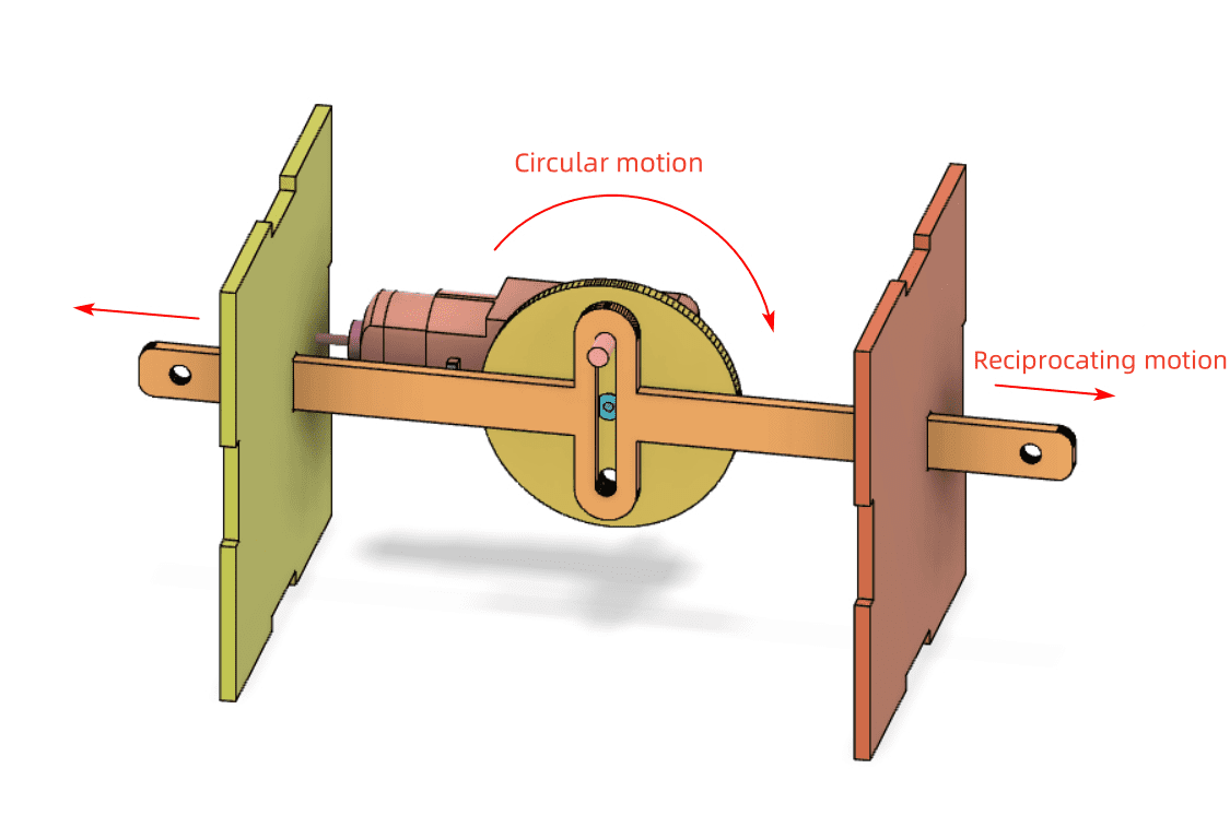
In this project, students use a motor-driven reciprocating mechanism to move the billboard left and right. The motor produces circular motion, while the anti-rotation yoke and sliding rod convert that circular motion into straight-line movement.


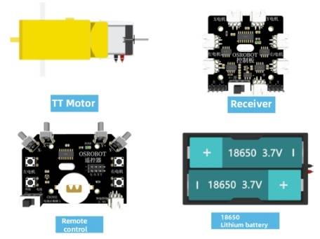
Before modeling the billboard, students should identify the electronic components, structural material, and hardware used in the project.
| Number | Item | Quantity |
|---|---|---|
| 1 | 2.4G Remote Controller with batteries | 1 |
| 2 | 2.4G Receiver | 1 |
| 3 | TT Motor, 1:120 | 1 |
| 4 | 18650 Battery with wires | 1 |
| 5 | Basswood Laminate, 40 cm × 60 cm × 3 mm | 1 |
| 6 | M3/M4 Screws and Nuts | Several |
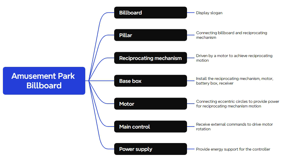
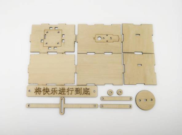
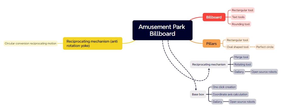
The laser-cut structure is organized into four main part groups: billboard, supports, reciprocating mechanism, and base enclosure.
| Part No. | Part Name | Quantity | Function |
|---|---|---|---|
| 1 | Billboard | 1 | Displays the advertisement or slogan |
| 2 | Supports | 2 | Connect the billboard to the reciprocating mechanism |
| 3 | Reciprocating Mechanism | 1 | Driven by the motor to create left-right movement |
| 4 | Base Enclosure | 1 | Houses the reciprocating mechanism, motor, battery, and receiver |
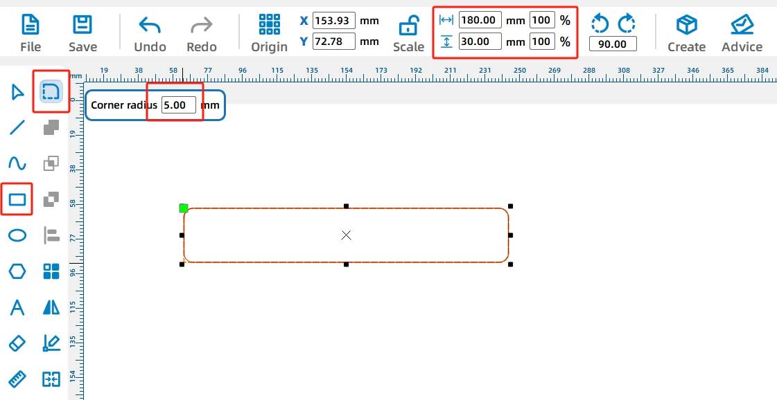
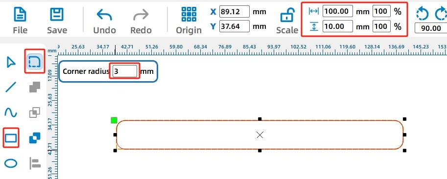
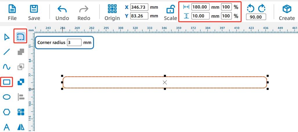
The billboard is based on a rounded rectangle. Use the Rectangle Tool to draw a 180 mm by 30 mm rectangle. Then use the Rounded Corner Tool with a 5 mm radius to round each corner.
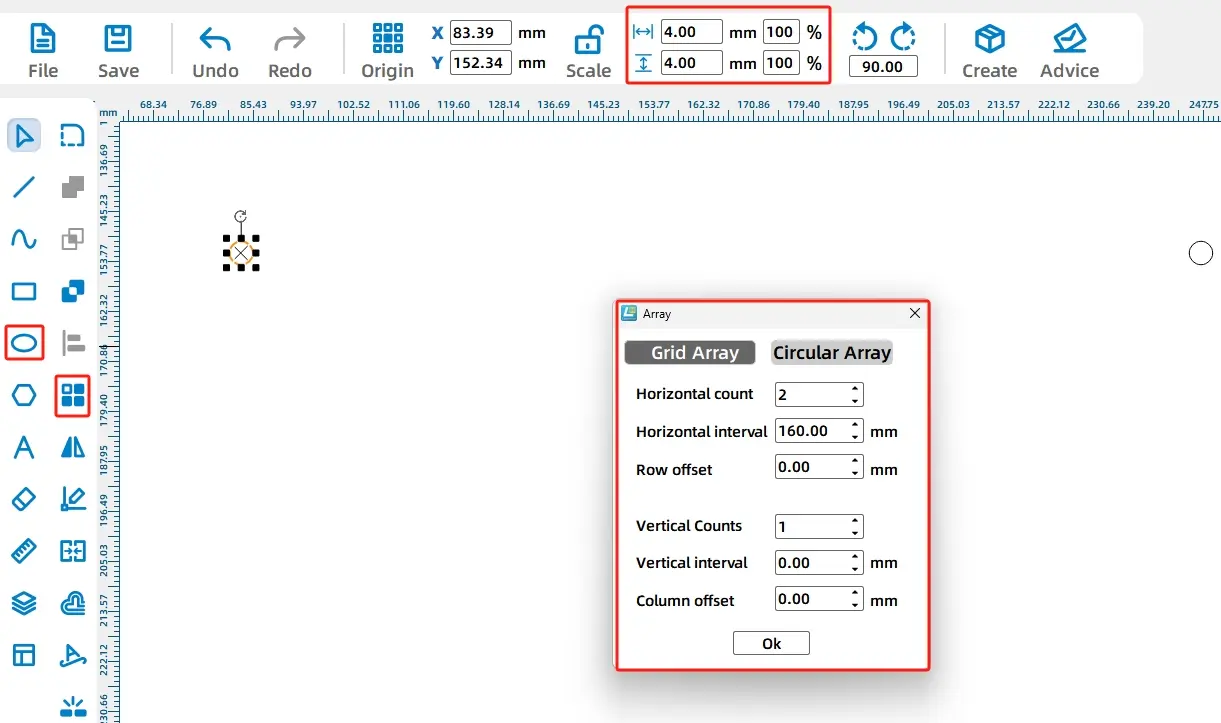
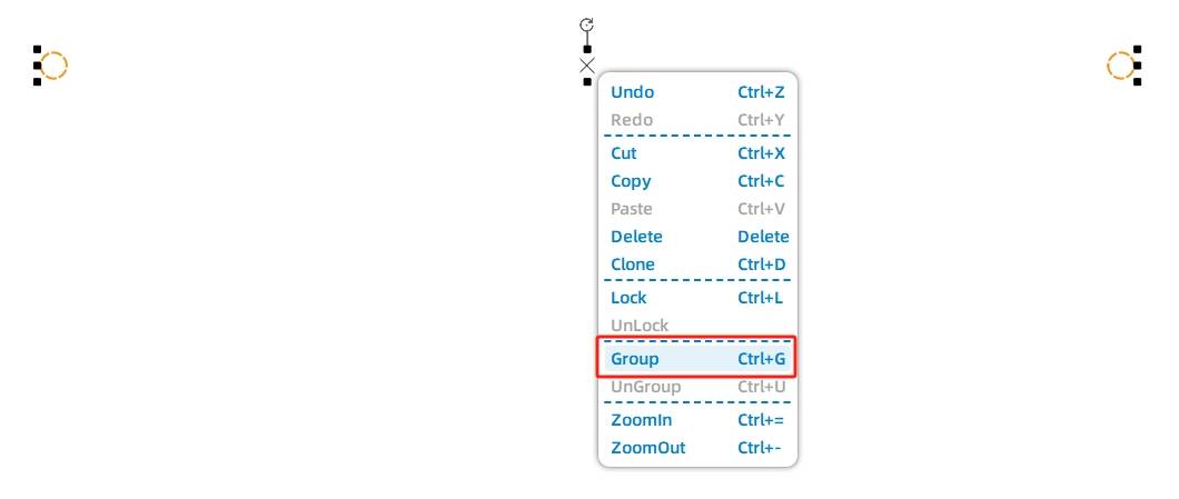
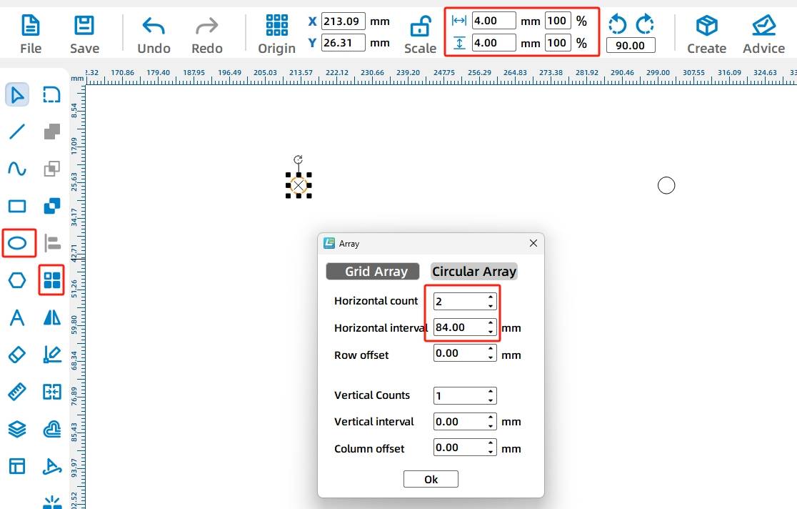
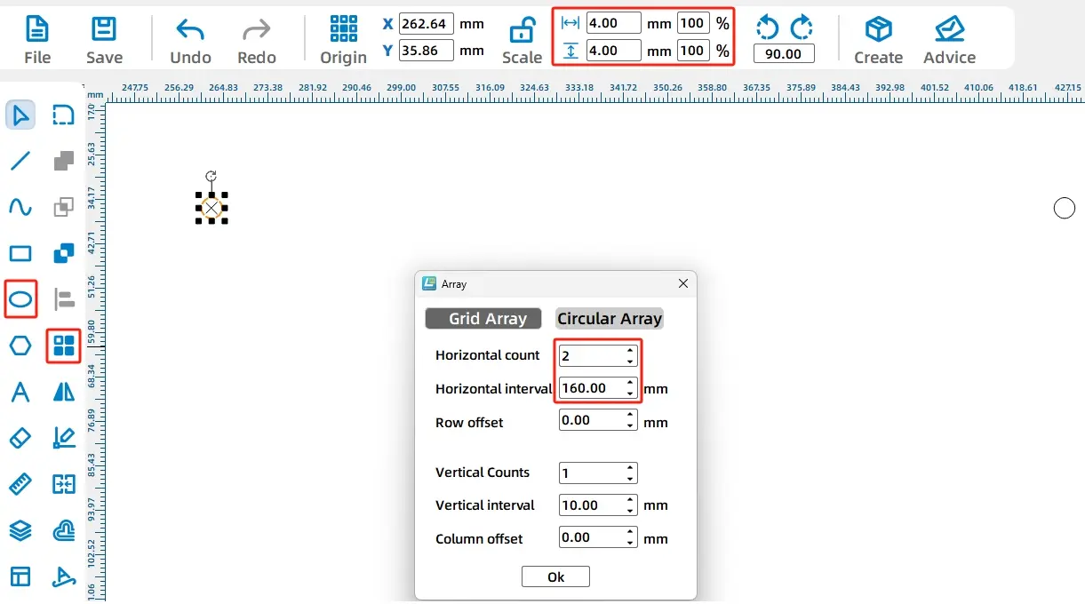
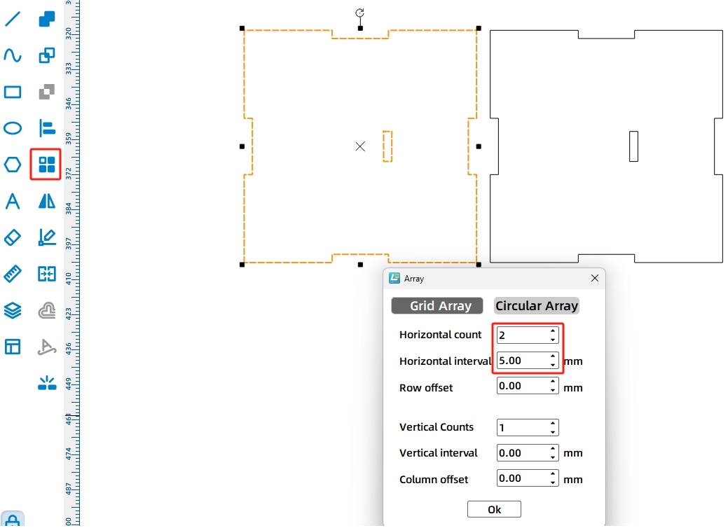
Next, draw two 4 mm circular holes for connecting the billboard to the supports. Use Rectangular Array with 2 horizontal copies and 160 mm horizontal spacing, then group the two holes together.
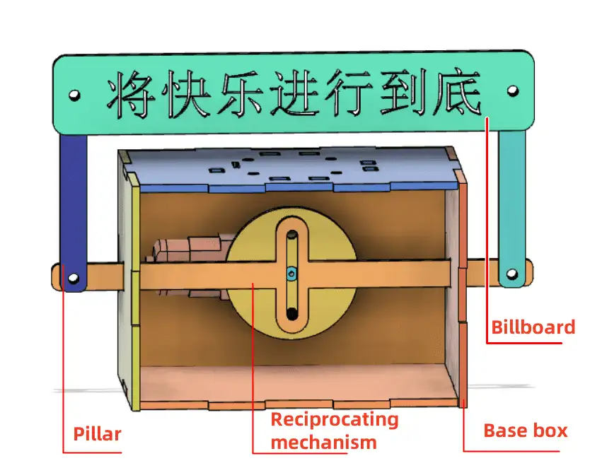
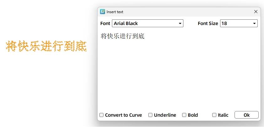
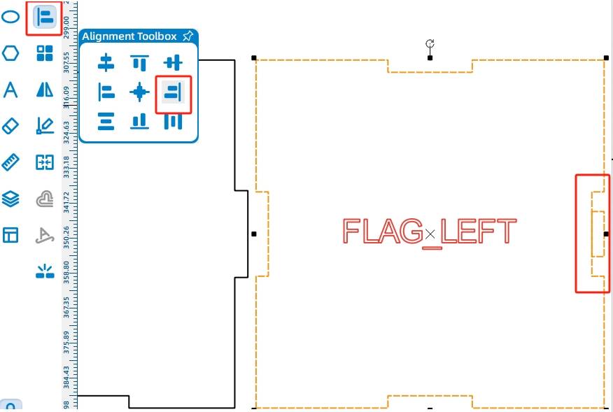
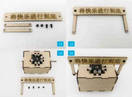
Use the Text Tool to add a slogan to the billboard. The source workflow uses the sample text “Enjoy the Joy to the Fullest.” Center-align the text, holes, and billboard outline so the sign looks balanced.
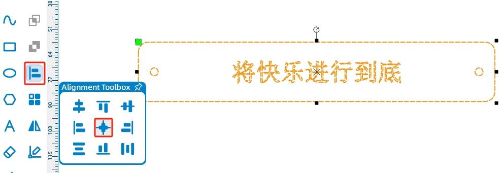
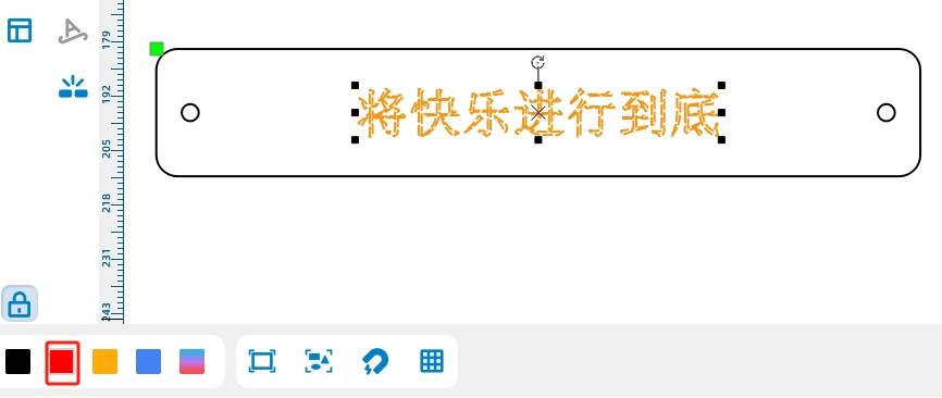
Set the slogan text to the red layer because it only needs to be marked on the surface. Keep the billboard outline and holes on the cutting layer.
The billboard uses two support rods to stand above the base and connect to the sliding mechanism. Draw one support as an 80 mm by 10 mm rectangle, then round each corner with a 3 mm radius.
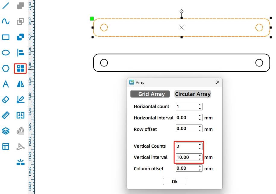
Draw two 4 mm circular holes in the support. Use Rectangular Array with 2 horizontal copies and 66 mm horizontal spacing, then group and center-align the holes within the support body.

Use Rectangular Array to create a second support. In the source workflow, the vertical count is 2 and the vertical spacing is 20 mm.
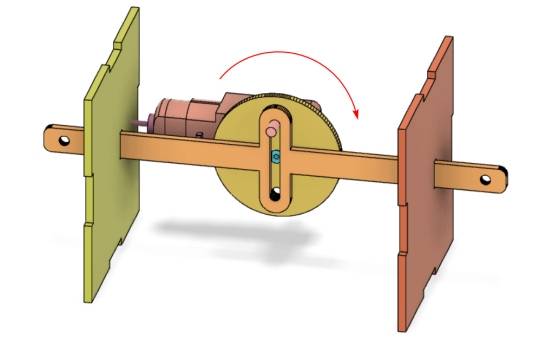
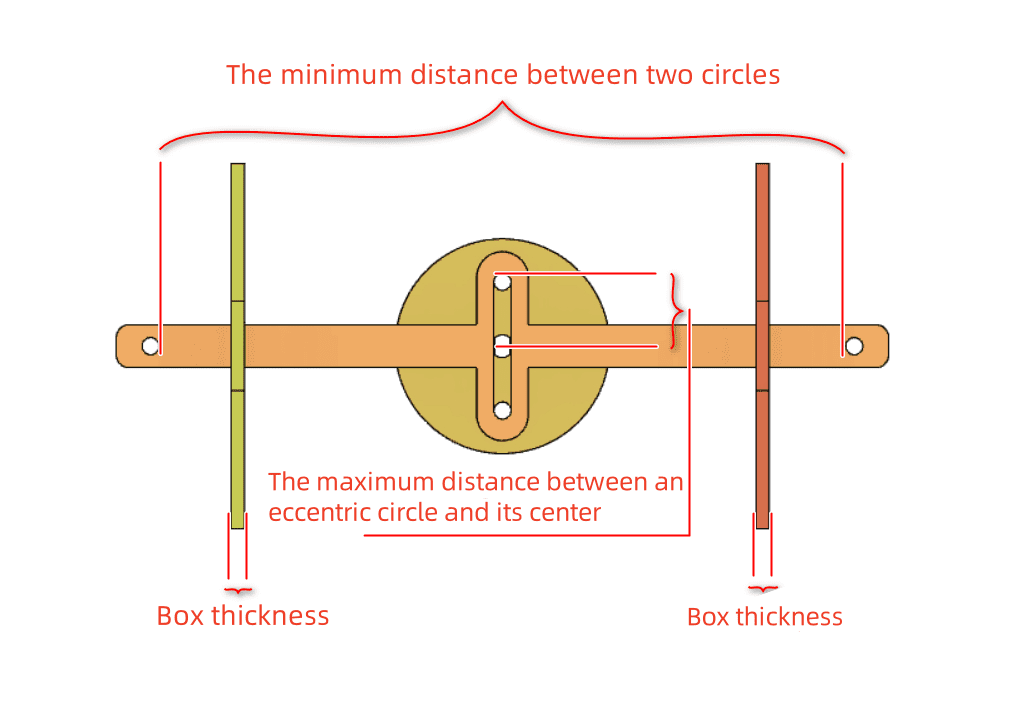
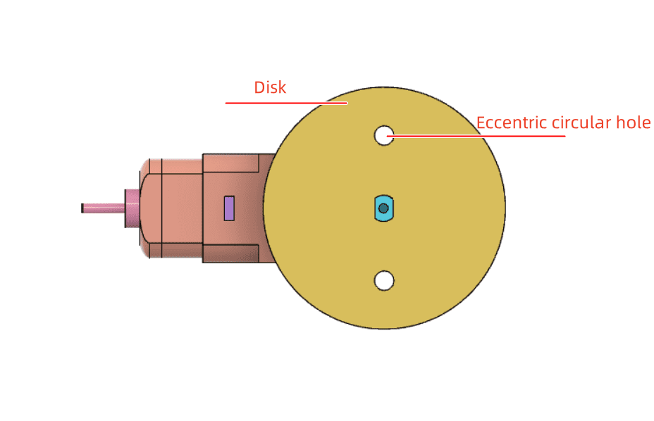
The reciprocating mechanism, also called an anti-rotation yoke mechanism in the source lesson, is the key part of this project. It includes a disc, an anti-rotation slot, and a sliding rod.
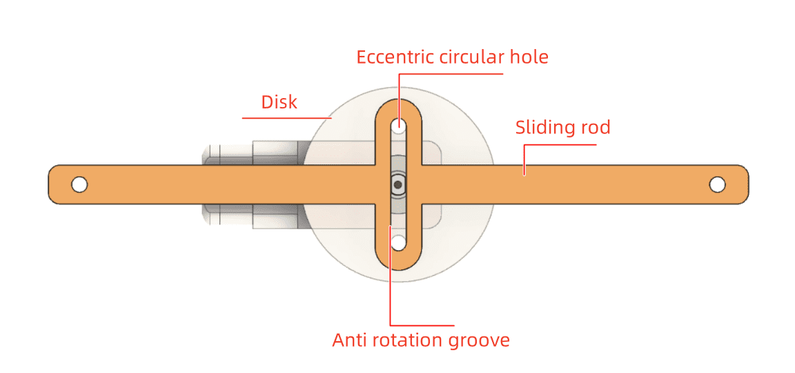
Mechanism Idea: As the eccentric hole on the disc rotates, it pushes against the slot and drives the sliding rod left and right. This converts circular motion into reciprocating linear motion.
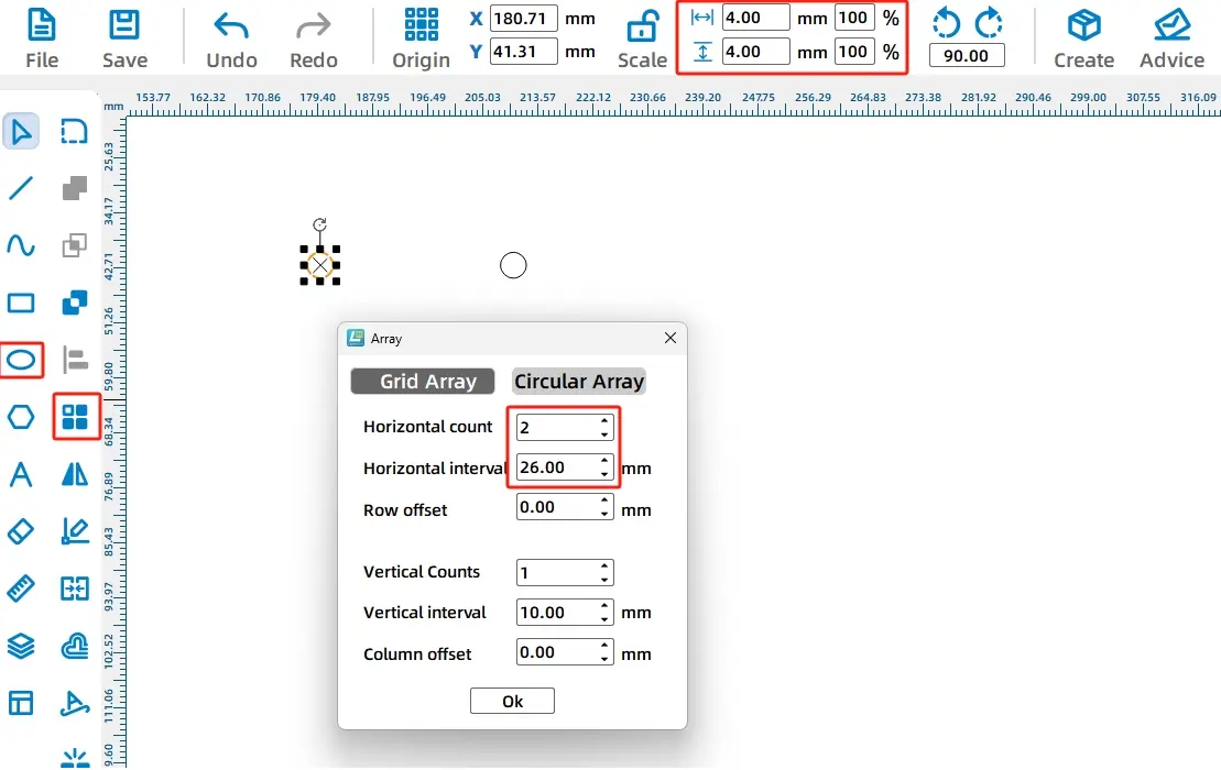
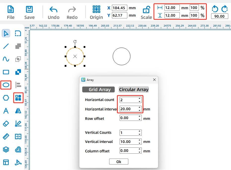
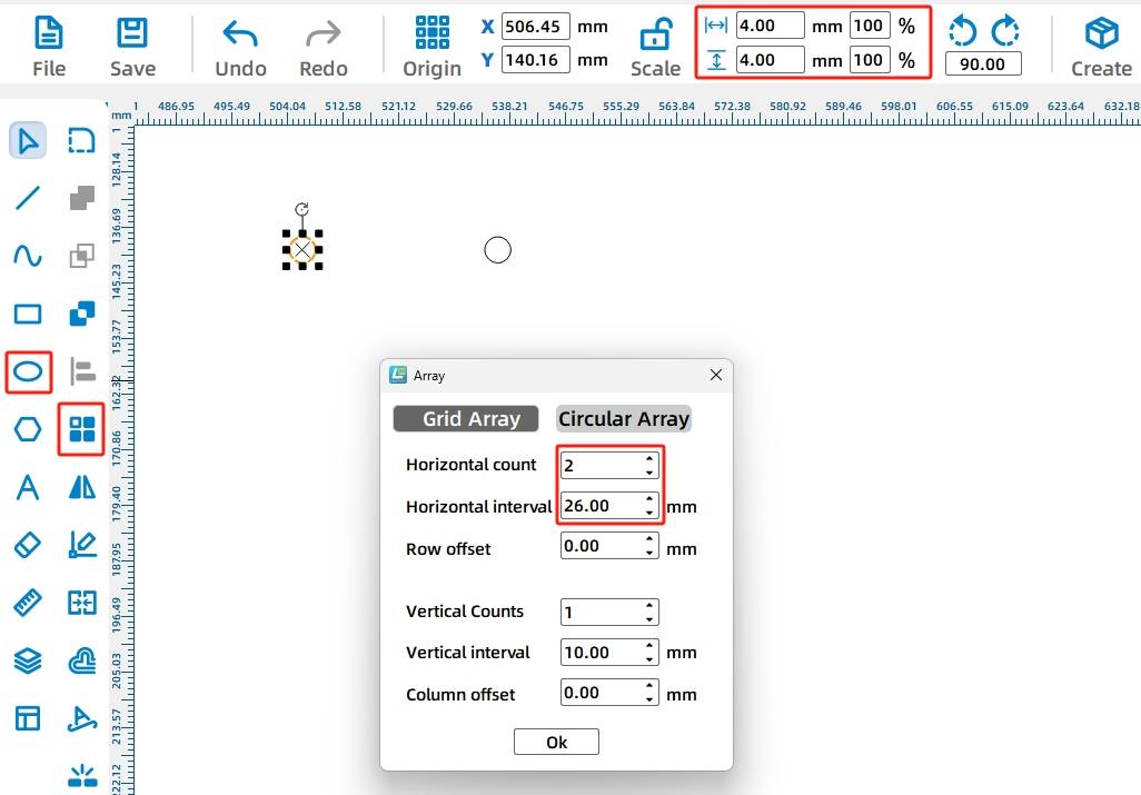
Draw two 4 mm circles and use Rectangular Array with 2 horizontal copies and 26 mm horizontal spacing. Then draw a 30 mm by 4 mm rectangle between the two circles. Align the shapes and use Union to merge them into the inner slot shape.

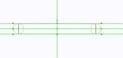
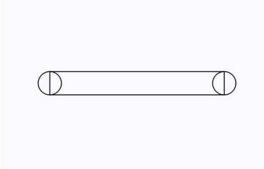
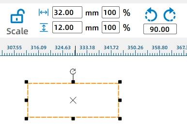
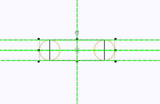
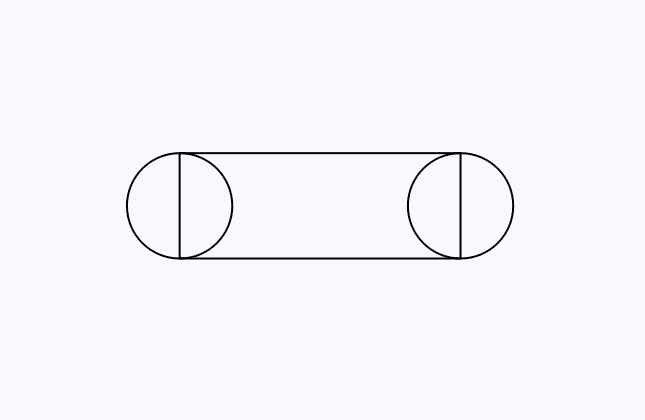
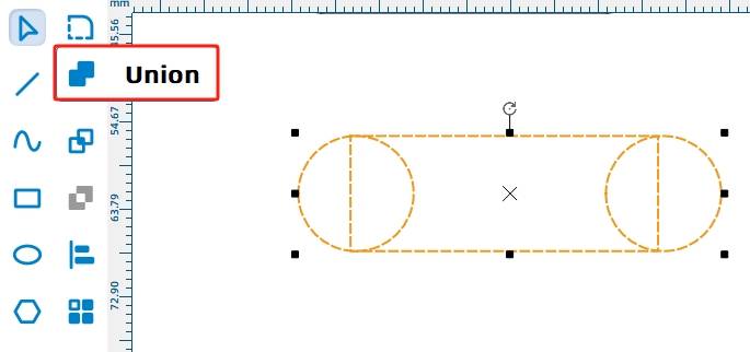
The outer contour of the anti-rotation yoke must be larger than the inner slot. Draw two 12 mm circles with a 20 mm horizontal spacing, then draw a 32 mm by 12 mm rectangle. Align the circles and rectangle, then use Union to create the outer yoke contour.
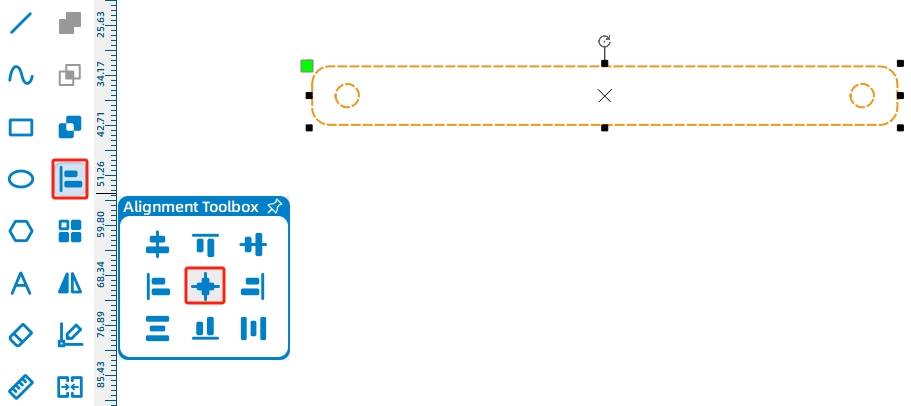
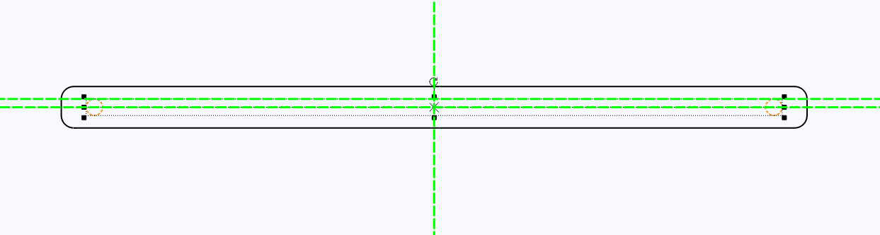
The sliding rod connects the billboard supports to the reciprocating mechanism. Draw two 4 mm circular holes with 160 mm horizontal spacing. Then draw a 180 mm by 10 mm rectangle, round its corners with a 3 mm radius, and align the two holes with the rod.
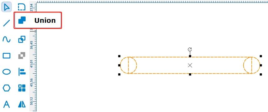
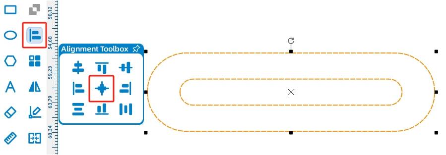
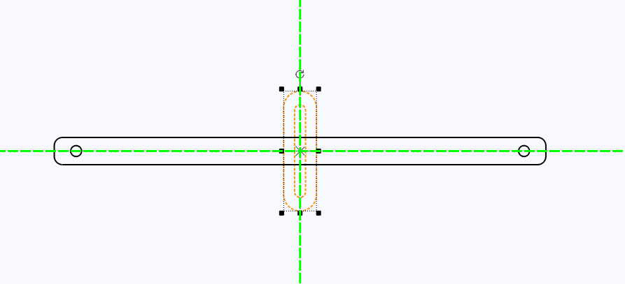
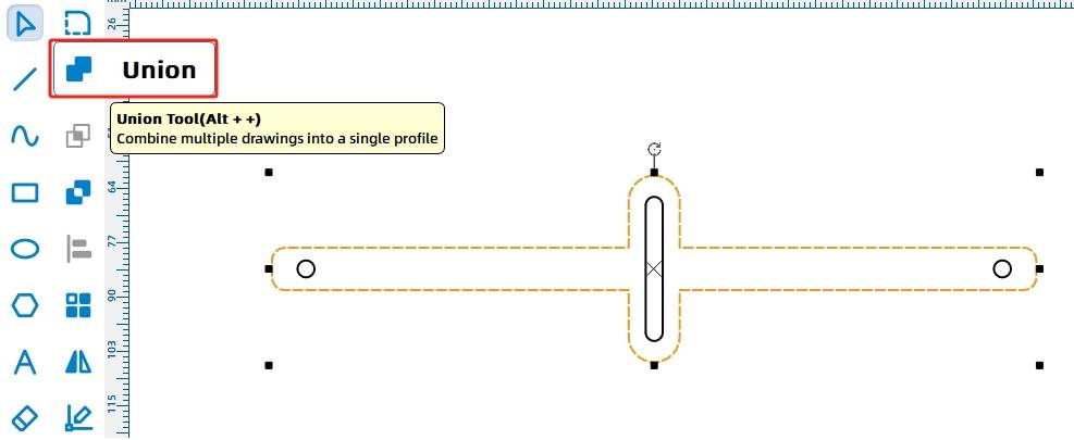
Rotate the anti-rotation yoke by 90 degrees, move it to the center of the sliding rod, and align it horizontally and vertically. Select only the outer contours of the rod and yoke, then use Union to merge them into one connected moving part.
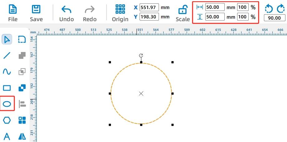
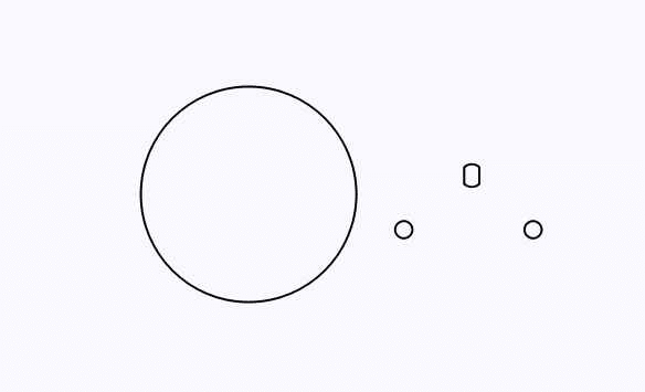
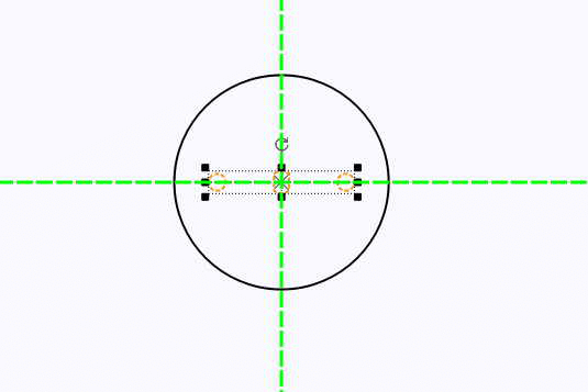
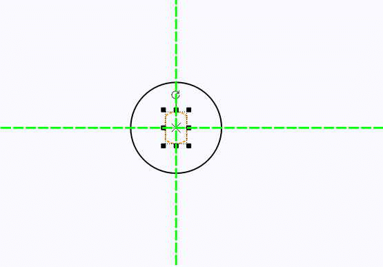
The disc drives the reciprocating mechanism. Draw two 4 mm eccentric holes with 26 mm spacing, then draw a 50 mm diameter circle for the disc. Add a TT motor shaft hole to the center of the disc and align the TT hole and eccentric holes with the disc center.
The source workflow uses two circular spacers on the TT motor shaft. These spacers help keep the motor shaft from interfering with the anti-rotation slot during rotation.
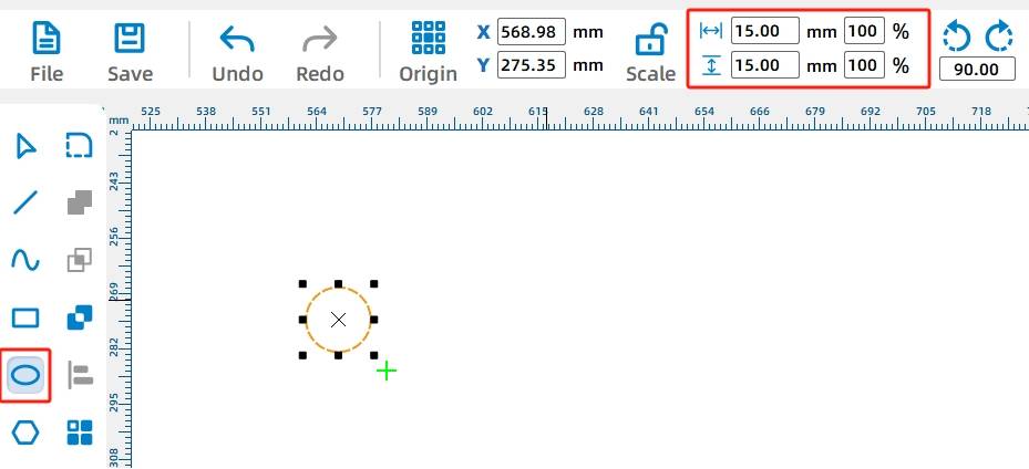
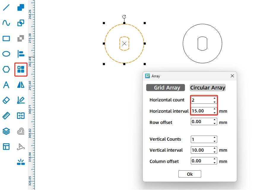
Draw a 15 mm circle, add a TT motor shaft hole to the center, then use Rectangular Array to duplicate the second spacer.
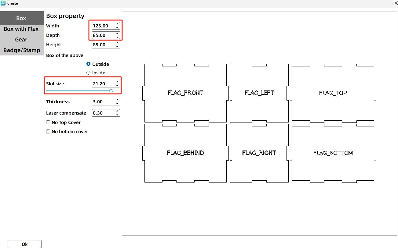
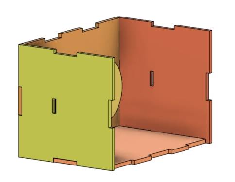
The box base fixes the motor, supports the sliding rod, and houses the battery and receiver. Use the One-Click Fabrication or Rectangular Box function to generate the box. In the source workflow, the dimensions are 125 mm length, 85 mm width, and 85 mm height, with external dimensions selected, 21.2 mm groove size, 3 mm material thickness, and 0.2 mm laser compensation.
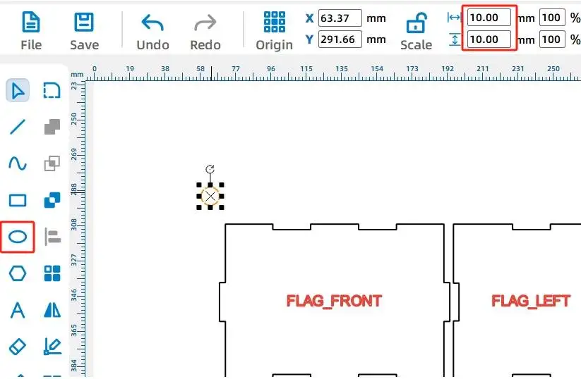
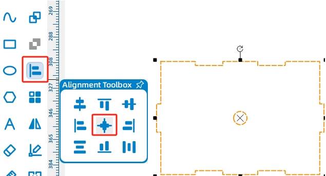
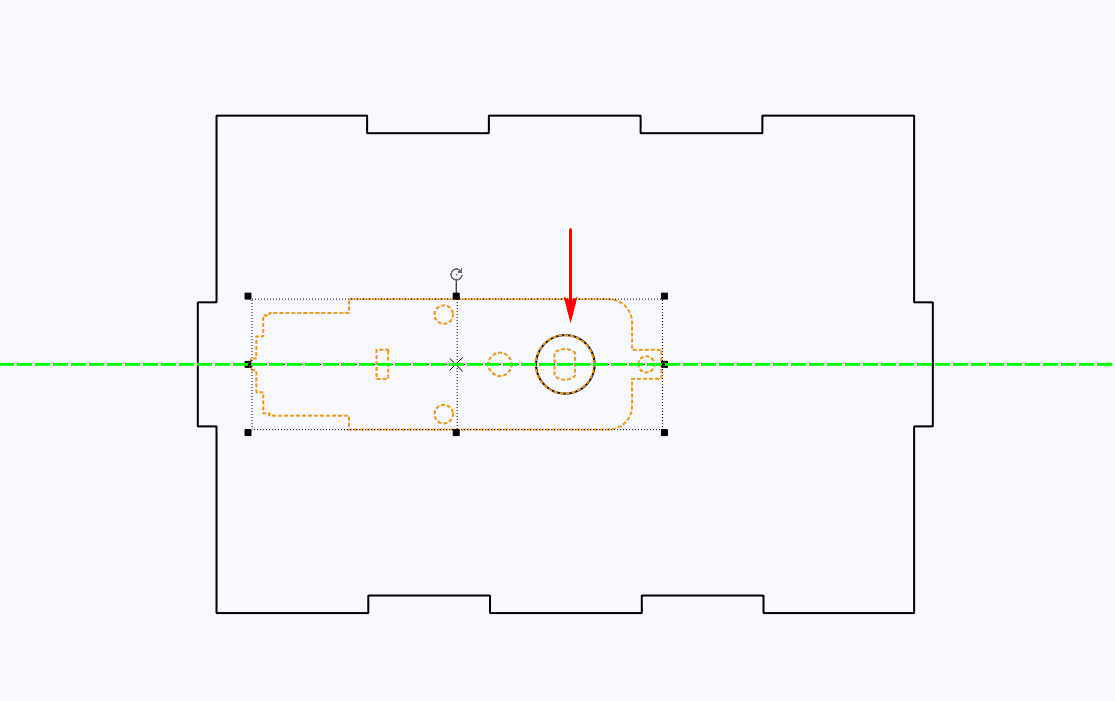
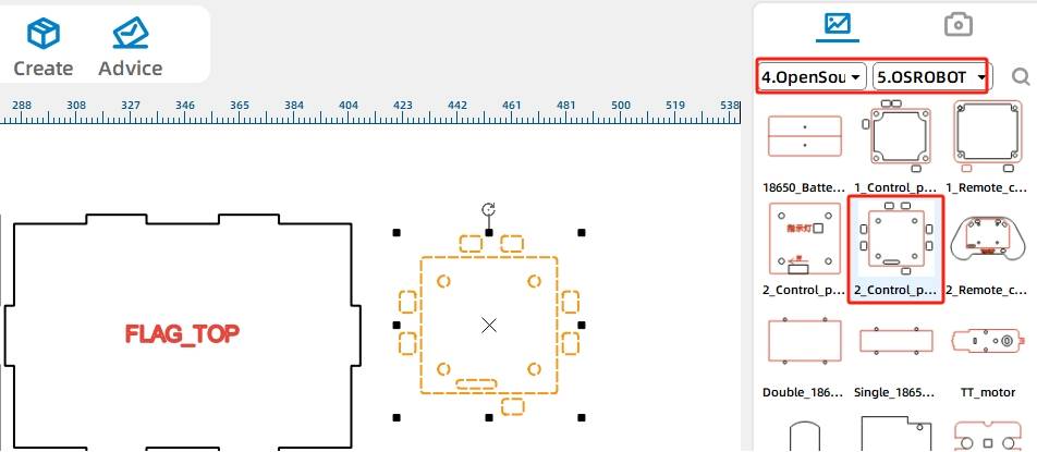
Move the front panel to an open area and draw a 10 mm circle to help position the TT motor shaft hole. Center-align the circle on the front panel, then add the OSROBOT Motor graphic and align the motor shaft hole with the circle.
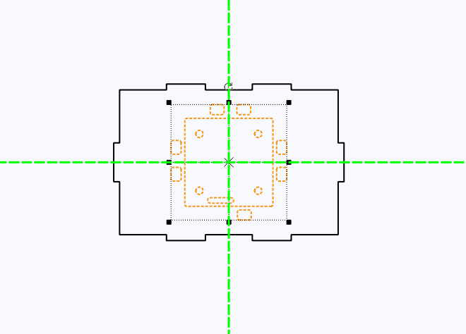
Move the top panel to an open area, add the 2.0 Control Board External graphic, group the board graphic, and center-align it on the top panel so the receiver can be mounted later.
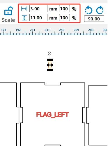
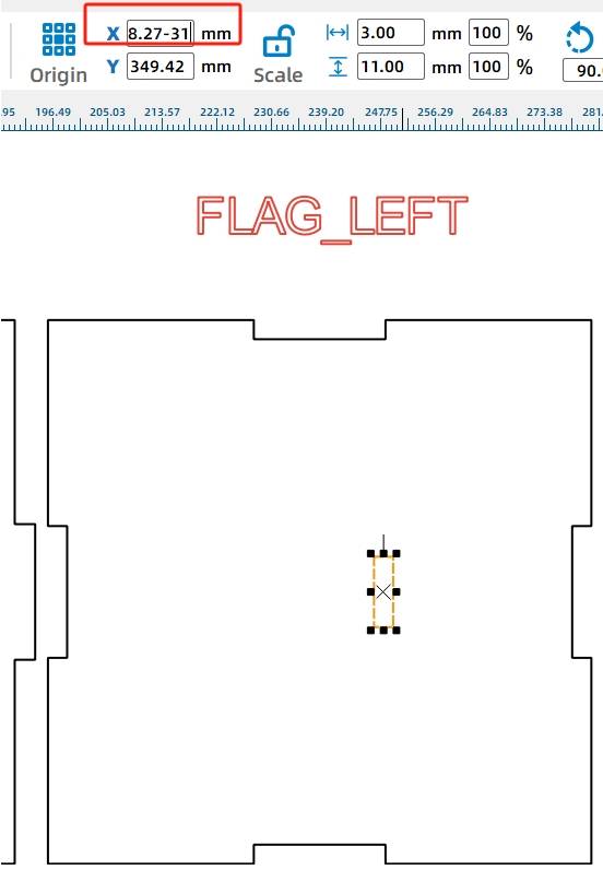
The sliding rod passes through both side panels of the box. Since the sliding rod is 10 mm high and made from 3 mm material, draw a slot that is slightly taller than the rod. In the source workflow, the slot is 3 mm wide and 11 mm high.
On the left side panel, draw a 3 mm by 11 mm rectangle. Align it to the right side and vertical center of the panel, then move it 31 mm left using the X-axis value. Use Rectangular Array to replicate the corresponding slot position for the other side panel.
After the billboard, supports, reciprocating mechanism, disc, spacers, and box base are complete, arrange the final drawing layout for laser processing.
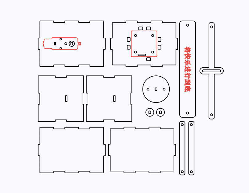
The billboard project uses two main laser processes. Red-layer objects are used for outlining or surface marking, while black-layer objects are cut through the basswood plywood.
Outlining: Double-click the red block in the processing parameters area. Select basswood plywood as the material, choose Outlining, and set the cutting depth to 0.10.
Cutting: Double-click the black block in the processing parameters area. Select basswood plywood as the material, choose Cutting, and set the cutting depth to 3.00.
Turn on the laser cutting machine and laser switch. When the Start Fabrication button is ready, upload the drawing to the laser cutting machine and start processing from the machine panel.
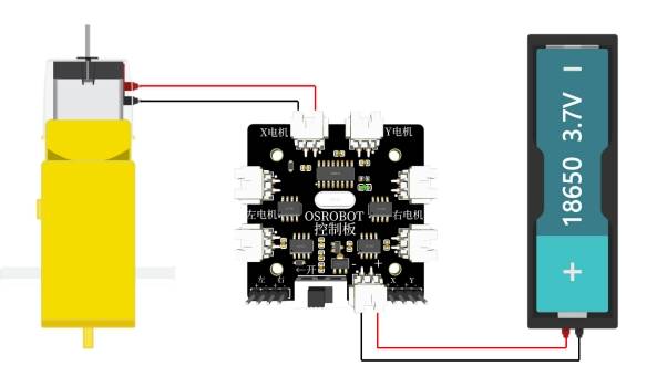
After the mechanical structure is prepared, connect the circuit according to the wiring diagram. The receiver, battery, and TT motor allow the billboard to move through remote control.
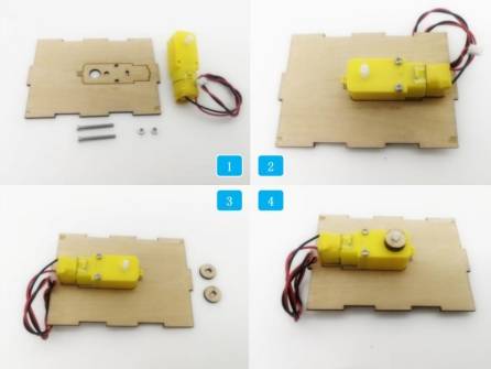
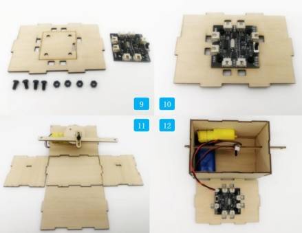
First, locate the TT motor, the motor mounting board, and the M3 screws and nuts. Install the TT motor onto the wooden board, then install the two 15 mm circular spacers onto the TT motor shaft.
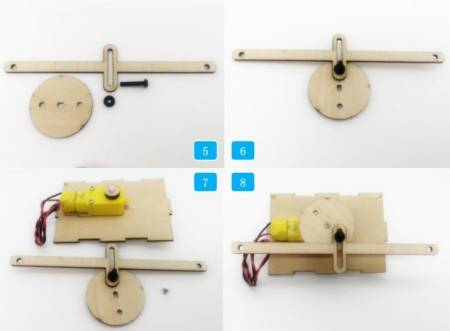
Next, locate the M4 screw, M4 gasket, sliding rod, and 50 mm disc. Use the screw to connect the anti-rotation slot with one eccentric hole on the disc. Then secure the disc onto the TT motor shaft with a self-tapping screw.
Install the receiver on its mounting board. Insert the sliding rod through the rectangular holes on both side panels, assemble the remaining box panels, and connect the wires according to the wiring diagram.
Finally, attach the support rods to the billboard with M4 screws and nuts. Install the top panel of the box, then connect the billboard and support rods to the sliding rod so the sign can move left and right.
Check whether the disc rotates smoothly without rubbing against the anti-rotation yoke.
Test whether the sliding rod moves freely through the side-panel slots.
Confirm that the support rods are firmly attached to both the billboard and sliding rod.
Review whether the box base stays stable while the billboard moves back and forth.
Check whether the slogan remains readable and whether the moving sign is visually clear from the front.
After design, laser processing, wiring, and assembly, students complete a moving amusement park billboard. The project gives students hands-on experience with LaserMaker drawing tools, measurement, coordinate movement, angle rotation, Union operations, powered motion, and reciprocating mechanism design.
Reciprocating mechanisms are used in many moving devices and displays. As an extension challenge, students can look for other real-life examples of non-rotating yoke or sliding mechanisms, then design a new project that uses a similar circular-to-linear motion principle.
Students can also redesign the billboard shape, change the slogan, adjust the eccentric-hole position, modify the sliding rod length, or build a different moving display for a store, museum, classroom, or event booth.
This project is suitable for classroom laser cutters that support cutting and outlining of sheet materials for small robotics and mechanism projects. For schools, makerspaces, and beginner STEAM labs, projects like moving billboards, reciprocating displays, remote-control signs, and motorized classroom models can be completed with a classroom laser cutter such as the Thunder Laser Bolt Series.
Teachers can choose the machine and material setup based on classroom space, project size, material thickness, electronic components, and learning goals. The same LaserMaker workflow can also be adapted for other CO2 laser machines when students move on to larger moving signs or more advanced mechanism projects.
Talk To Our Experts Now!
Please leave your contact information so that we can serve you better.
NEED HELP FINDING THE RIGHT SOLUTION?
Talk to our team for machine recommendations, application advice, and support based on your needs.

 Stable & Consistent MachinesUnlimited ApplicationRobust After-sales SupportFactory Direct Supply


