


Remote-Control Ring Toss Game Laser Cutting Project for STEAM Classrooms
 2024-07-18
WHAT ARE YOU LOOKING FOR?
Search Across Products, Blog Posts, Support Content, And Resources.

Remote-Control Ring Toss Game Laser Cutting Project for STEAM Classrooms
2024-07-18

In this STEAM robotics and mechanism project, students design and build a remote-control ring toss game using LaserMaker. The lesson connects laser-cut box structures, gift holders, gear transmission, cam mechanisms, reciprocating motion, game rings, TT motor control, wiring, and hands-on assembly.
This project turns a familiar amusement-park game into a moving classroom model. Students explore how a rotating motor and gear set can drive a cam, and how the cam can convert circular motion into up-and-down movement for the gift holders.
| Item | Details |
|---|---|
| Project | Remote-control ring toss game device |
| Software | LaserMaker |
| Main Skills | Right-angle box creation, Text Tool, support-foot design, OSROBOT motor graphics, gear placement, cam design, rectangular arrays, mortise-and-tenon joints, game ring drawing, laser cutting, wiring, and assembly |
| Suggested Material | Basswood plywood, 40 cm × 60 cm × 3 mm |
| Classroom Fit | Robotics and mechanism projects, cam mechanisms, gear transmission, game design, maker education, laser cutting, and remote-control structures |
Students will design a ring toss game with a base, moving gift holders, a rotating cam mechanism, gear transmission, and game rings. They will prepare the laser-cut parts in LaserMaker, set scoring and cutting processes, assemble the mechanical structure, connect the electronic components, and test whether the gift holders move smoothly.
For teachers: Use this project to connect circular motion, linear reciprocating motion, gears, cams, measurement, game design, and laser-cut assembly.
For students: Use the activity to build a working ring toss game while learning how mechanisms can make game targets move.
For makerspaces: Use it as a powered game project that combines laser cutting, gears, cams, wood parts, electronics, and remote control.
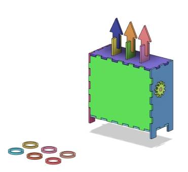
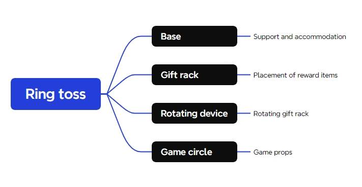
Analyze a ring toss game and divide it into a base, gift holder, rotating mechanism, and game rings.
Use LaserMaker to generate and modify an open box base with text, support feet, mounting holes, and component positions.
Use gears and a cam mechanism to convert motor rotation into linear up-and-down motion.
Create gift holders with mortise-and-tenon connections and arrow-shaped targets for the game rings.
Draw game rings, set laser processing, assemble the model, and connect the motor, receiver, and battery.
Design thinking: Improve a traditional ring toss game by adding moving targets and a clear game structure.
Computational thinking: Use dimensions, hole spacing, arrays, alignment, gear placement, and cam sizing to build a precise digital model.
Engineering thinking: Consider motor position, shaft fit, gear engagement, cam clearance, gift-holder movement, base stability, and safe wiring.
Students should test powered and moving parts carefully under teacher or lab supervisor guidance. Keep hands, loose wires, and small objects away from gears, cams, rotating shafts, and moving gift holders during operation.
A ring toss game asks players to throw rings onto targets or prizes. The game becomes more challenging when the target size, throwing distance, or target position changes.
In this project, students create moving gift holders using a motor-driven cam. The motor rotates the gear set, the gear set turns the wooden shaft, and the cam lifts the gift holder to create a changing target position.

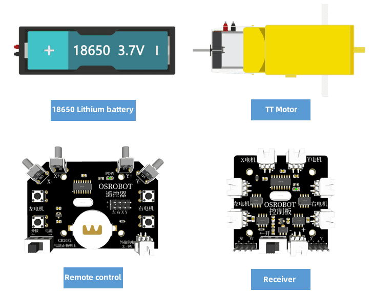
Before modeling the ring toss device, students should identify the electronic components, structural materials, shaft material, and hardware used in the project.
| No. | Name | Quantity |
|---|---|---|
| 1 | 2.4G remote control with battery | 1 |
| 2 | 2.4G receiver | 1 |
| 3 | TT motor, 1:120 | 1 |
| 4 | 18650 battery with wire | 1 |
| 5 | Basswood plywood, 40 cm × 60 cm × 3 mm | 1 |
| 6 | M3 screws and nuts | Several |
| 7 | 6 mm diameter wooden rod | 1 piece |
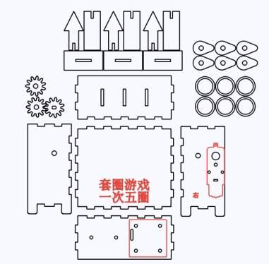
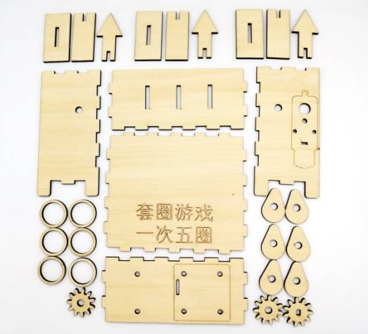
The ring toss game structure is organized into four main part groups: base, gift holder, rotating mechanism, and game rings.
| Part No. | Part Name | Quantity | Function |
|---|---|---|---|
| 1 | Base | 4 | Secures the brackets, battery box, and receiver |
| 2 | Gift Holder | 9 | Holds the gifts or target positions |
| 3 | Rotating Mechanism | 8 | Moves the gift holder up and down |
| 4 | Game Rings | 5 | Game props for throwing |
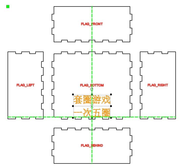
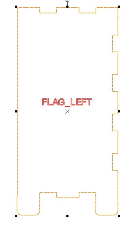
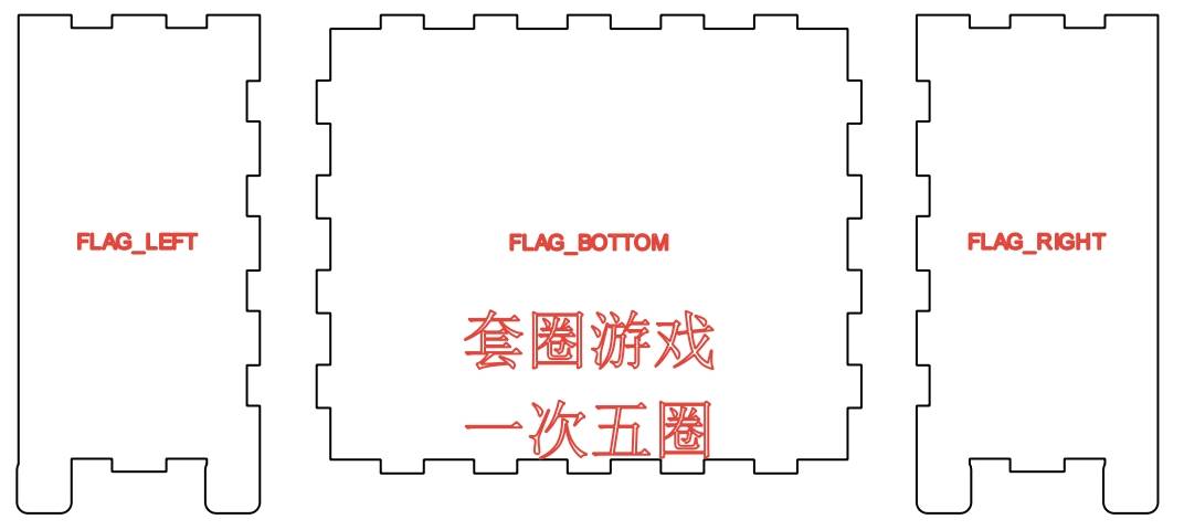
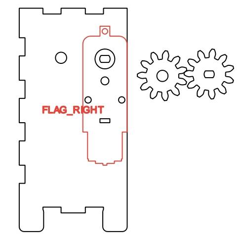
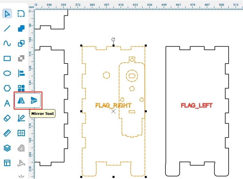
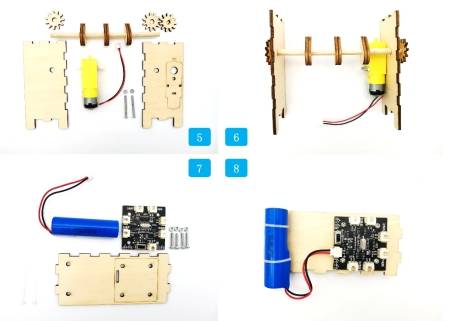
The base is designed as an open box so students can access the motor, battery, receiver, and moving mechanism. In the source workflow, the box is created with the right-angle box tool and later rearranged to work as a base without a rear cover.
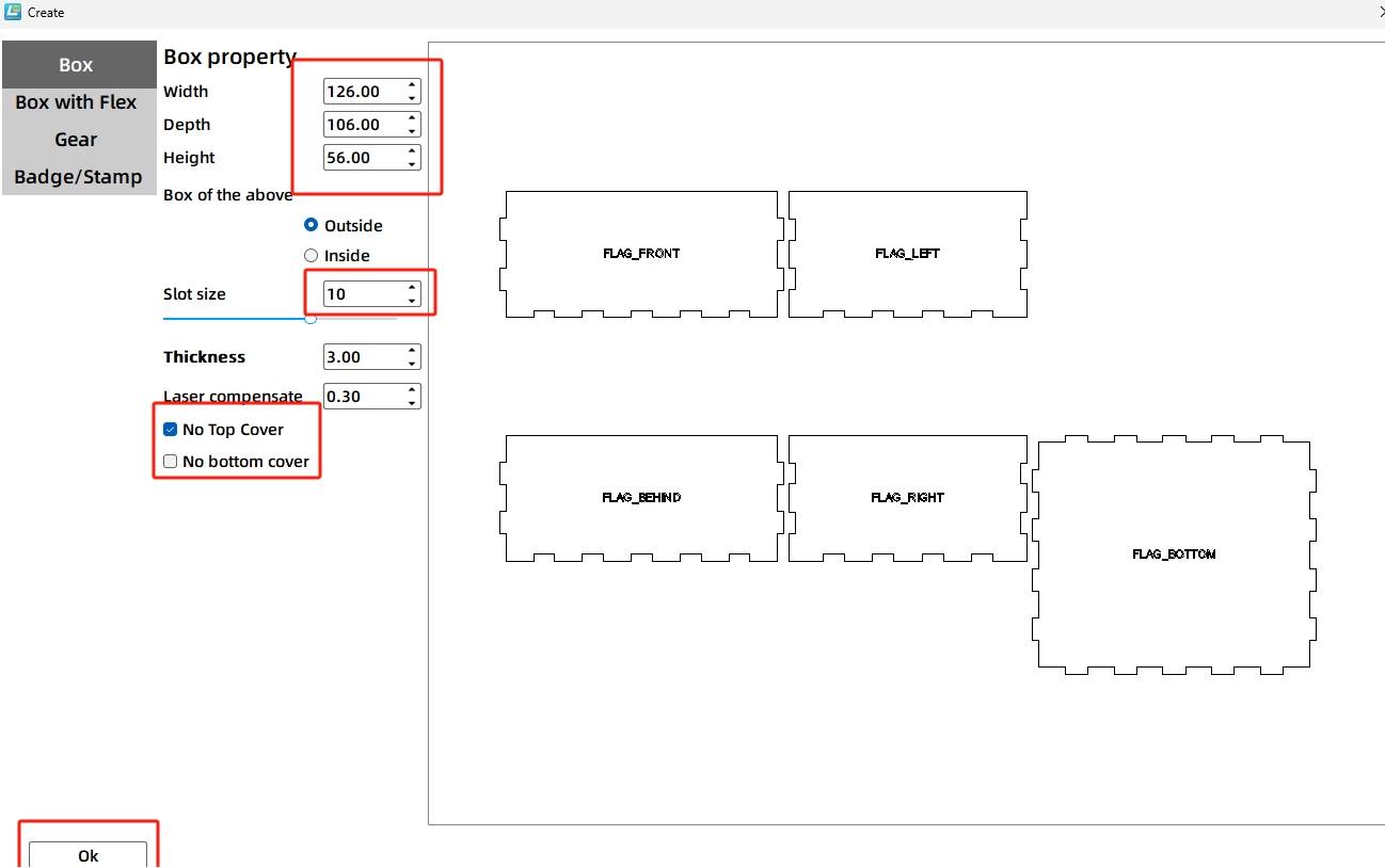
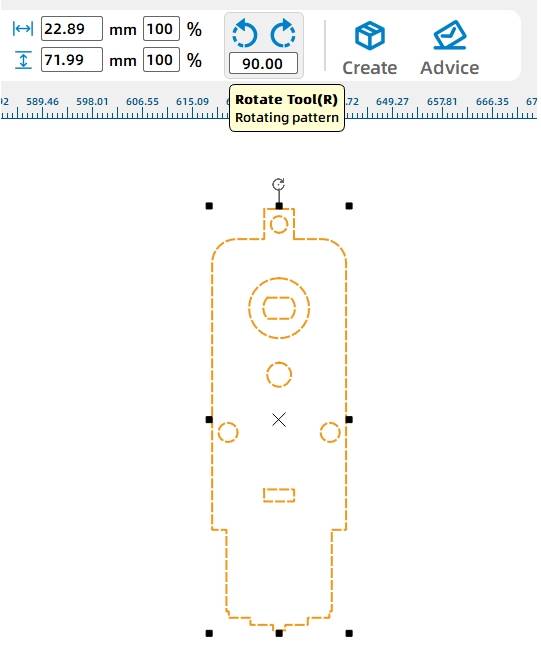
Open LaserMaker, click Creation from the tool menu, and create a right-angle box. In the source workflow, the length, width, and height are set to 126 mm, 106 mm, and 56 mm. The groove size is set to 10 mm, and the No Top Cover option is selected.
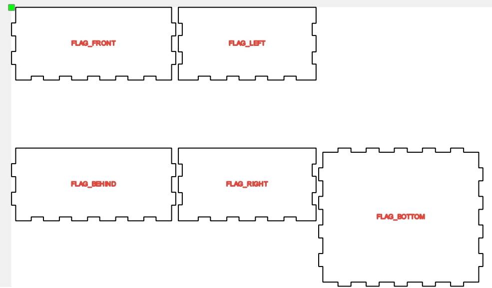
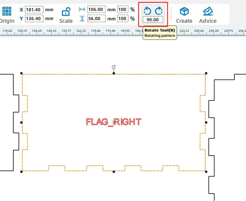
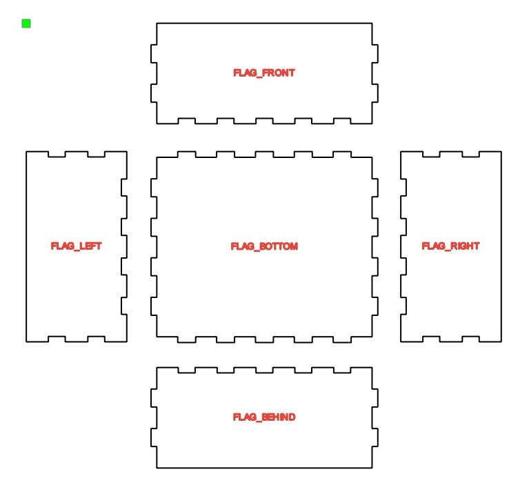
Rearrange the panels so each surface is easier to edit. Rotate and move the right and left panels, then place the front and back panels above and below the bottom panel. Move the prompt labels to the corresponding panels and delete extra prompts.
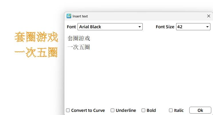
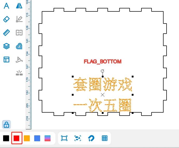
Add the game instructions to the front panel using the Text Tool. In the source workflow, the text says “Ring Toss Game” and “5 Rings per Turn.” Since the text is only a prompt, set its process to scoring instead of cutting.
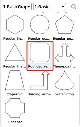
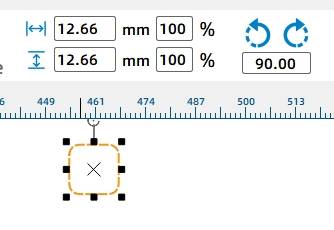
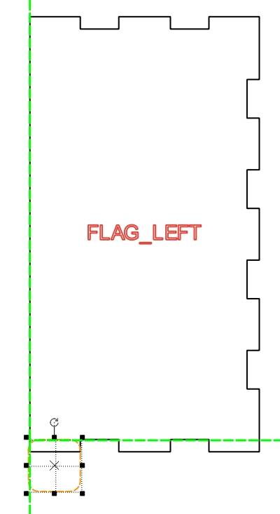
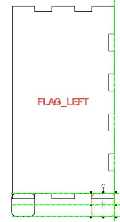
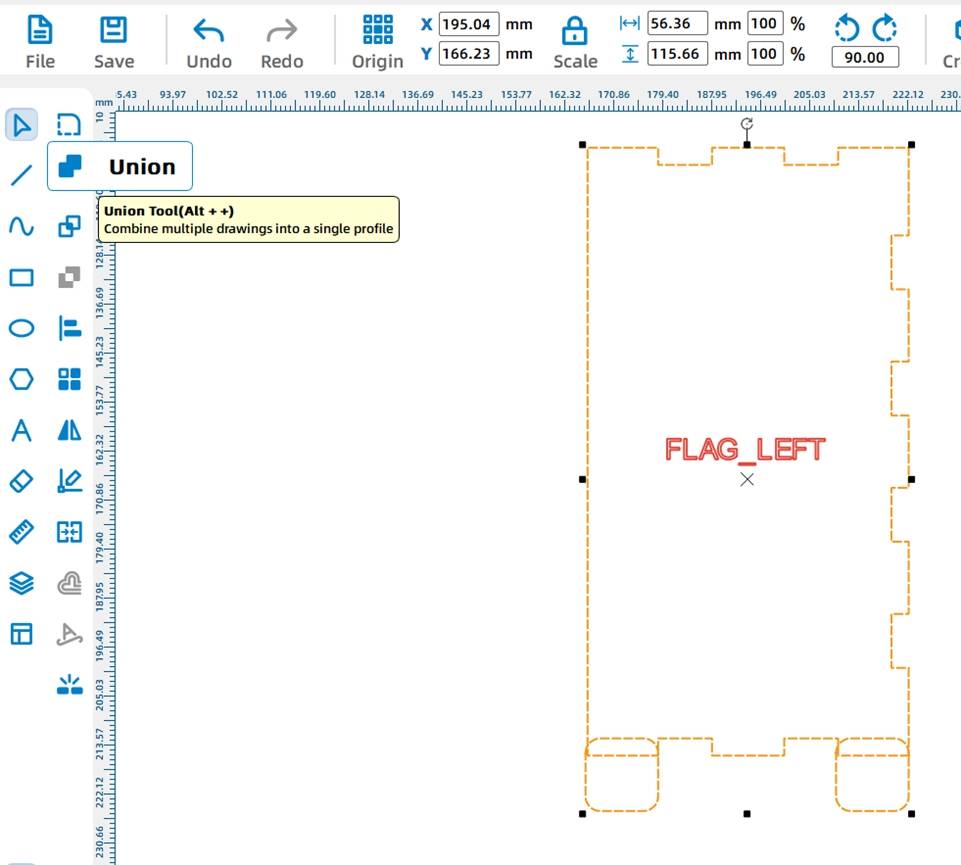
Because the bottom of the base holds electronics and fasteners, support feet are added to keep the box stable. Select a rounded rectangle from Basic Shapes. In the source workflow, the leftmost bottom tenon is measured as 12.66 mm wide, so the rounded rectangle is resized to 12.66 mm by 12.66 mm.
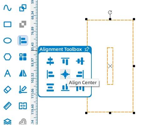
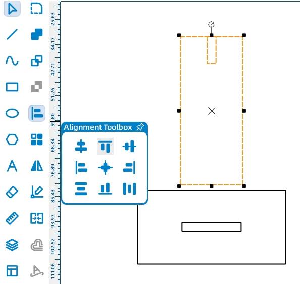
Move the rounded rectangle to the bottom of the left panel. Copy and paste another rounded rectangle to the right side of the panel. Select the panel and support feet, then use Union to integrate the shapes. Repeat the same process for the right panel.
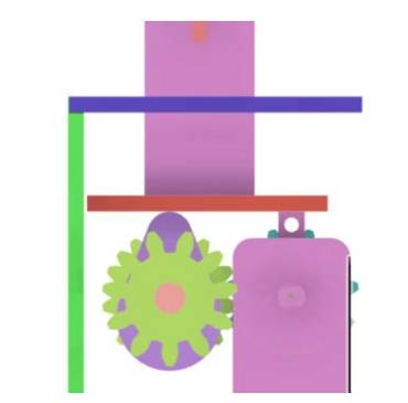
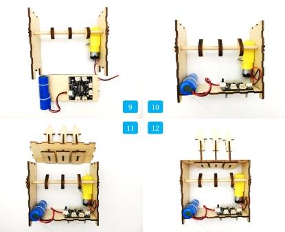
The rotating mechanism uses a TT motor, a gear set, a wooden shaft, and cams. The motor drives the gears, the gears rotate the shaft, and the cams push the gift holders up and down.
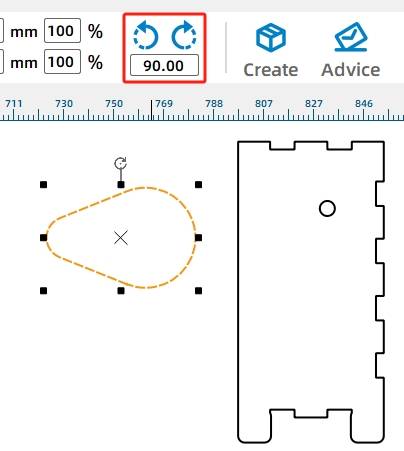
Select the OSROBOT Motor graphic from the Open Source Robot library and drag it onto the canvas. Rotate the motor graphic by 90 degrees.
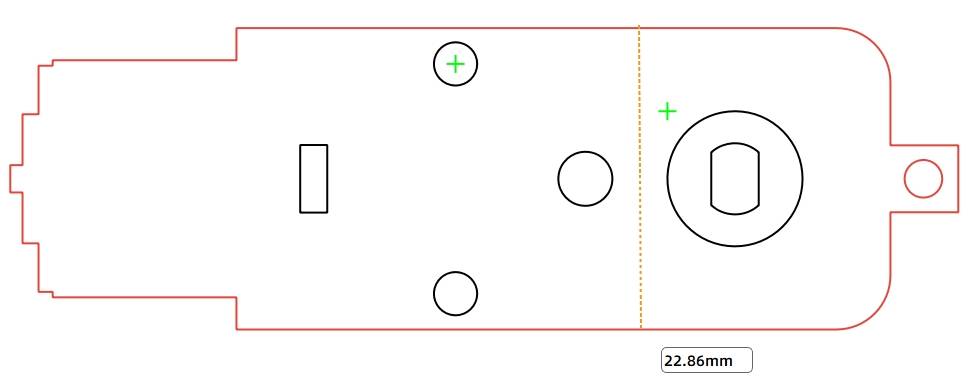
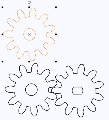
To connect the motor to the wooden shaft, add a gear set to the outside of the base. In the source workflow, students select the M2 11t Round Hole from Mechanical Parts, place it over the TT motor, and align it with the motor center. A second matching gear is then added and aligned with the first gear.
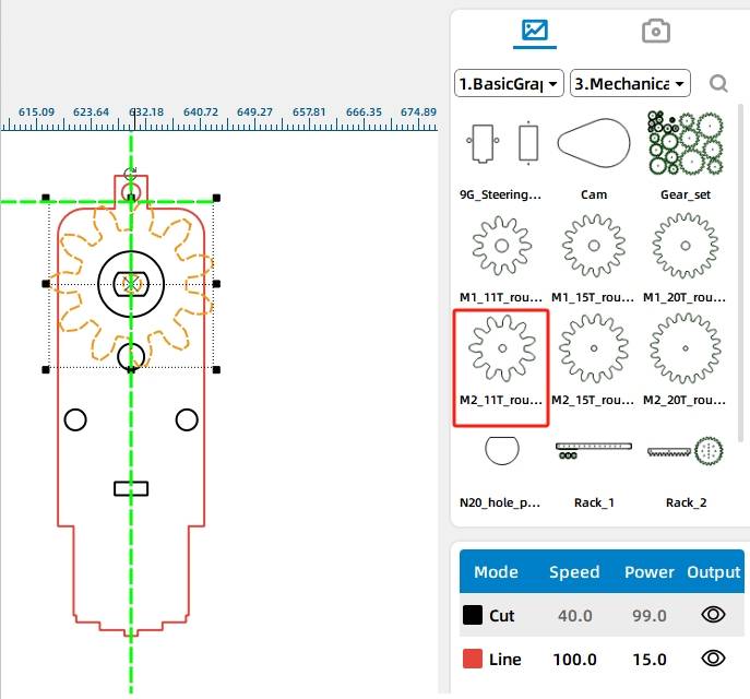
Move the TT motor and gear set onto the right panel. Align the bottom of the motor with the lowest mortise on the panel. The round shaft hole through the base is set slightly larger than the 6 mm wooden rod to reduce friction, so the hole on the panel is changed to 6.2 mm.
.jpg)
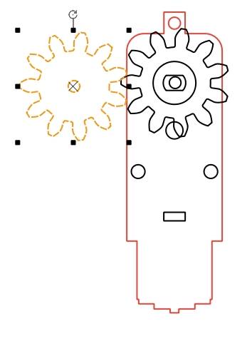
The gear that connects directly to the wooden shaft needs a slightly tighter hole. Copy the gear set and set the left gear inner circle to 5.8 mm so it can grip the 6 mm shaft more securely. Delete unnecessary gear components on the right panel.
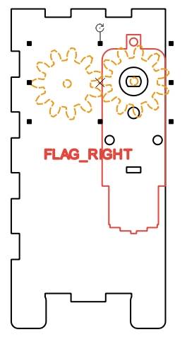
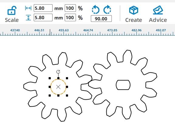
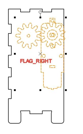
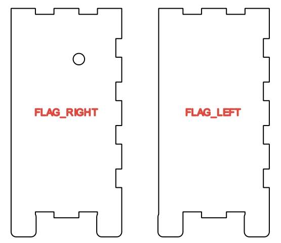
Copy the right panel and use it to create a matching left panel with the aligned shaft hole. Remove extra holes and prompts, leaving only the round shaft hole. Add another round-hole gear on the left side of the shaft to help keep the shaft from detaching during rotation.
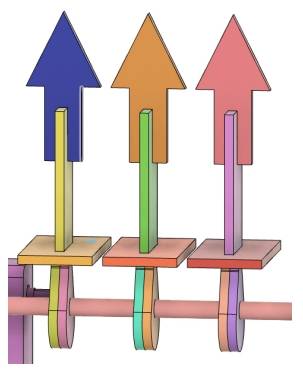
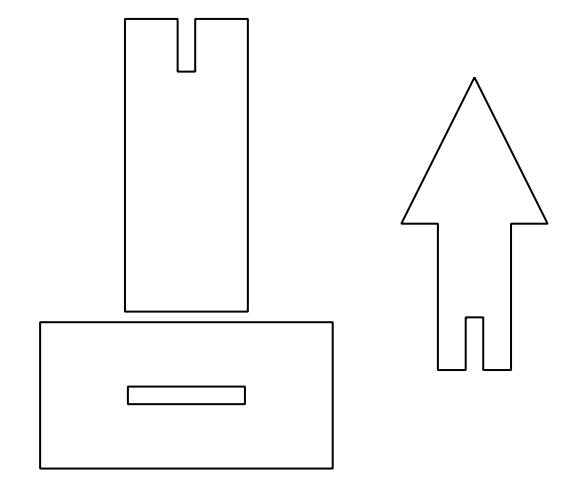
The gift holder uses a vertical structure so three targets can fit within the base width. Each gift holder includes a base that contacts the cam, a middle connector, and an arrow-shaped top for the ring.
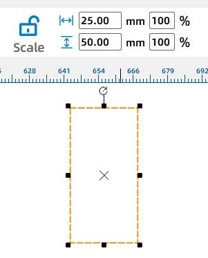
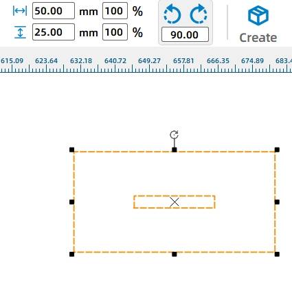
Start with the gift holder base. Draw a 25 mm by 50 mm rectangle, then draw a 3 mm by 20 mm rectangle inside it. Center-align the two rectangles to create the mortise position.
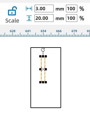
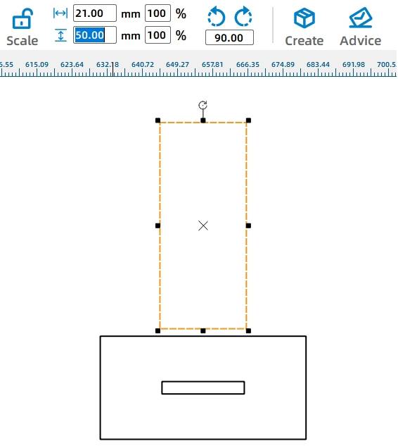
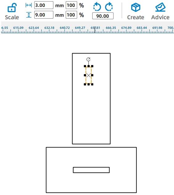
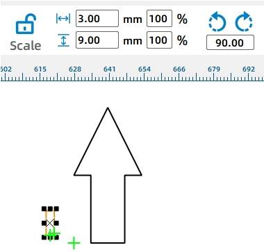
For the middle connector, draw a 21 mm by 50 mm rectangle. Then draw a 3 mm by 9 mm rectangle near the top so the arrowhead can be inserted later. Align the smaller rectangle to the top center and use Difference to create the mortise.
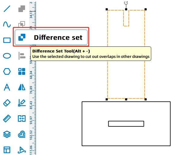
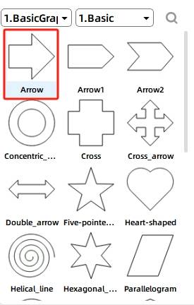
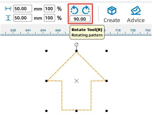
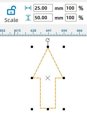
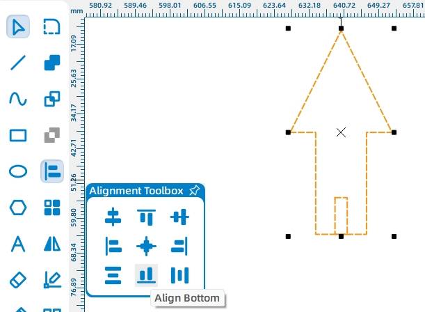
For the arrow-shaped top, choose the Arrow graphic from Basic Shapes, rotate it upward by 90 degrees, and set its width to 25 mm. Add a 3 mm by 9 mm mortise rectangle, align it to the bottom center of the arrow, and use Difference to create the insertion feature.

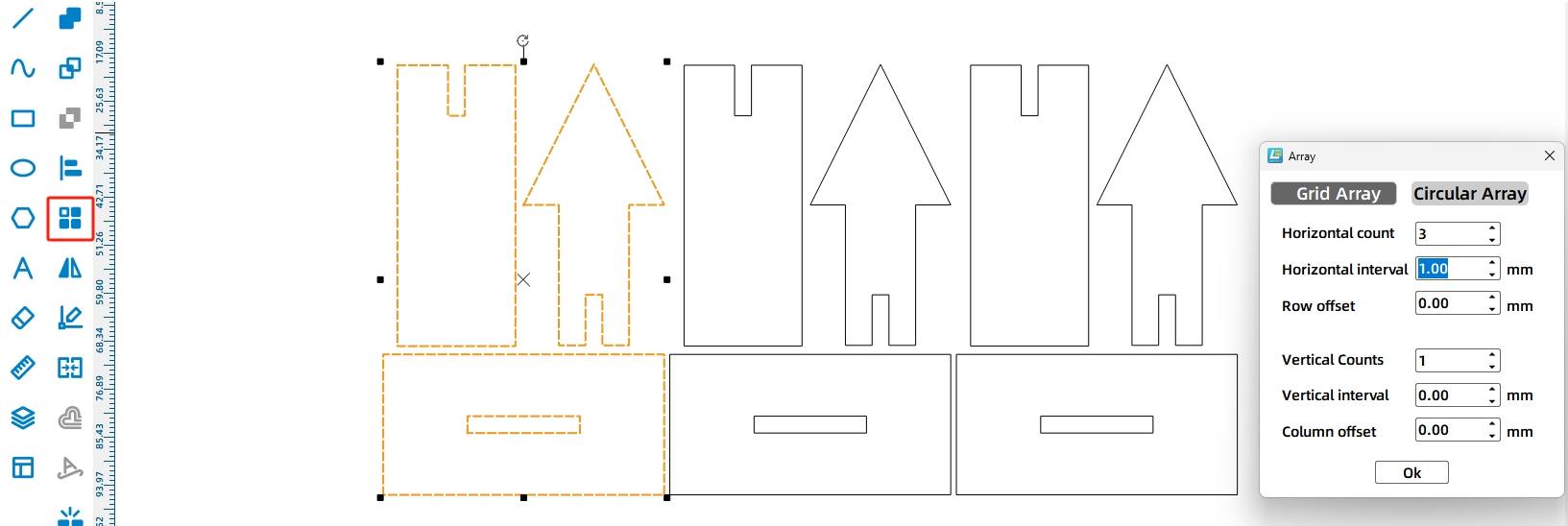
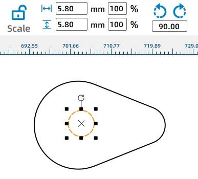
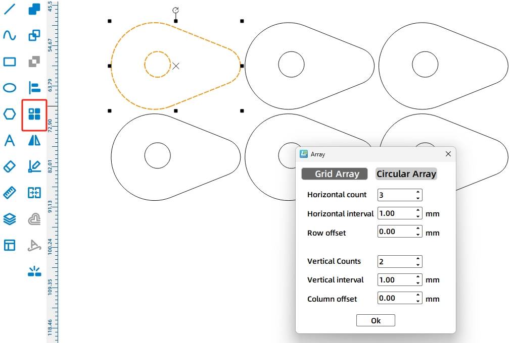
After completing one gift holder, use Rectangular Array to create three identical gift holders.
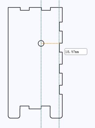
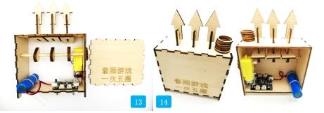
The cam is the key mechanism that lifts the gift holders. Select the Cam graphic from Mechanical Parts and drag it onto the canvas. Add auxiliary lines to estimate the distance from the shaft hole center to the bottom of the panel mortise. In the source workflow, this distance is about 18.97 mm.
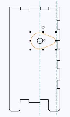
Scale the cam down to 45% so it will not hit the base while rotating. Then add a 5.8 mm shaft hole at the cam center so it can fit tightly onto the 6 mm wooden rod. To increase contact area with the gift holder base, the source workflow stacks two cams together.
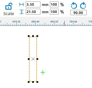
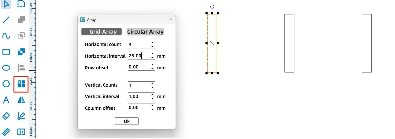
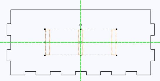
Draw rectangular slots on the top panel so the gift holders can move up and down. In the source workflow, each slot is 3.5 mm wide and 21.5 mm high. Use Rectangular Array to create three slots with 25 mm spacing, then move them to the center of the top panel.
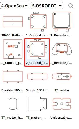
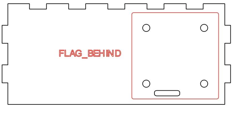
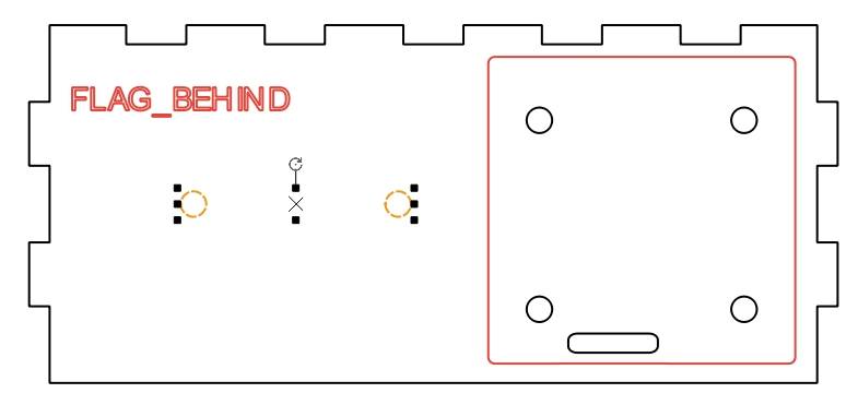
Add the OSROBOT receiver board from the Open Source Robot library to the base panel. Since the motor, battery, and receiver are hidden inside the base, delete unnecessary wire holes. Copy the receiver board screw holes to create mounting holes for the 18650 battery cable ties.
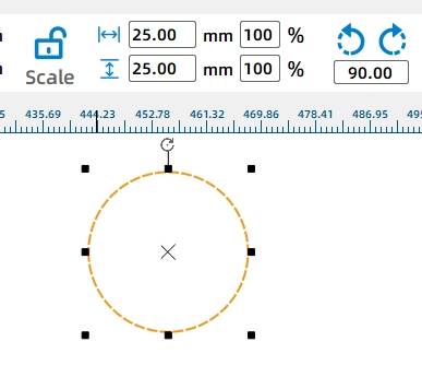
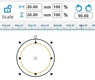
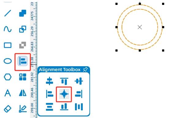
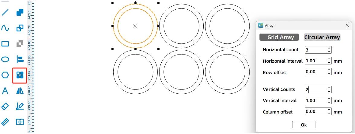
The game rings are made from two concentric circles. Use the Ellipse Tool while holding Ctrl to draw circles with diameters of 25 mm and 20 mm. Center-align the two circles to create one ring, then use Rectangular Array to create six rings with 1 mm spacing.
Before saving, delete annotations and auxiliary lines that are no longer needed.
After completing the design, check the laser process settings again. Use simulation to confirm the sequence of scoring and cutting before sending the file to the laser cutting machine.
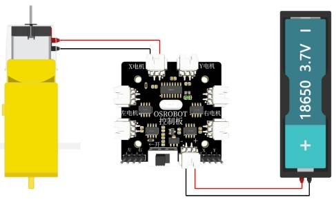
After cutting the parts, connect the circuit according to the wiring diagram. The source workflow notes that the ring toss game should not move too quickly, so the setup uses one 18650 battery and a geared motor in the wiring example.
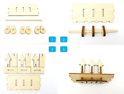
First, locate the cams, wooden stick, and upper panel of the base. Install the cams on the wooden stick according to the hole spacing on the upper panel. Then locate the three bottom supports of the gift holders, the arrows, and the middle vertical plates.
Next, locate the left and right panels, gear set, rotating shaft, and accessories. Secure the motor to the right panel, pass the rotating shaft through the left and right panels, and fix both ends with round-hole gears. Install the gear with the TT hole onto the motor so it engages with the gear on the rotating shaft.
Find the bottom panel, 18650 battery, receiver, nylon cable ties, screws, and nuts. Secure the receiver and battery to the base using the hardware and ties.
Install the rotating mechanism on the bottom panel. Then install the upper panel with the gift holders onto the base.
Finally, install the front panel with the game instructions and place the game rings on the gift holders.
Check whether the cams rotate smoothly without hitting the base or top panel.
Test whether the gift holders move up and down freely through the top-panel slots.
Confirm that the gears mesh well and that the shaft does not slip or detach during operation.
Review whether the base stays stable after the receiver, motor, battery, screws, and ties are installed.
Check whether the rings are easy to pick up, throw, and land on the arrow-shaped gift holders.
After design, laser processing, wiring, and assembly, students complete a remote-control ring toss game with moving targets. The project gives students hands-on experience with gear transmission, cam mechanisms, laser-cut boxes, mortise-and-tenon gift holders, game ring design, and powered motion.
In the finished project, the gift holders use wooden arrow shapes. As an extension challenge, students can add text prompts to the gift holders, redesign them as small gift boxes, or create a new target system that makes the game easier to understand for players.
Students can also brainstorm other daily-life examples of gear transmission and cam mechanisms, then design another moving project that uses the same circular-to-linear motion principle.
This project is suitable for classroom laser cutters that support cutting and scoring of sheet materials for small robotics and mechanism projects. For schools, makerspaces, and beginner STEAM labs, projects like ring toss games, cam-driven targets, remote-control game devices, and gear transmission models can be completed with a classroom laser cutter such as the Thunder Laser Bolt Series.
Teachers can choose the machine and material setup based on classroom space, project size, material thickness, electronic components, and learning goals. The same LaserMaker workflow can also be adapted for other CO2 laser machines when students move on to larger game devices or more advanced mechanism projects.
Talk To Our Experts Now!
Please leave your contact information so that we can serve you better.
NEED HELP FINDING THE RIGHT SOLUTION?
Talk to our team for machine recommendations, application advice, and support based on your needs.

 Stable & Consistent MachinesUnlimited ApplicationRobust After-sales SupportFactory Direct Supply


