


Remote-Control Happy Ferris Wheel Laser Cutting Project for STEAM Classrooms
 2024-07-19
WHAT ARE YOU LOOKING FOR?
Search Across Products, Blog Posts, Support Content, And Resources.

Remote-Control Happy Ferris Wheel Laser Cutting Project for STEAM Classrooms
2024-07-19

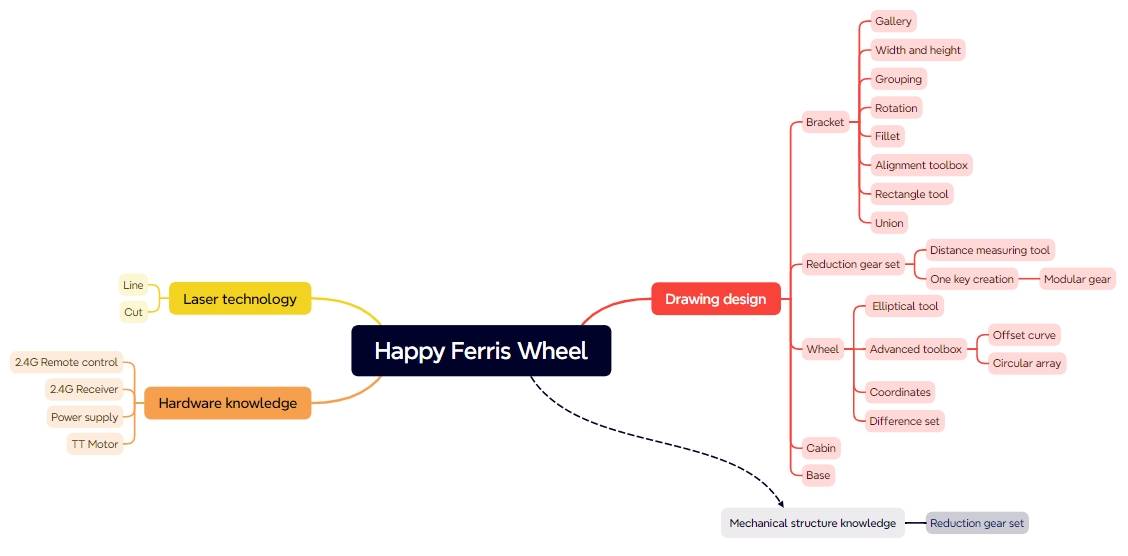
In this STEAM robotics and mechanism project, students design and build a remote-control Ferris wheel using LaserMaker. The lesson connects amusement-ride observation, laser-cut structures, gear reduction, cockpit design, bracket support, TT motor control, wiring, and hands-on assembly.
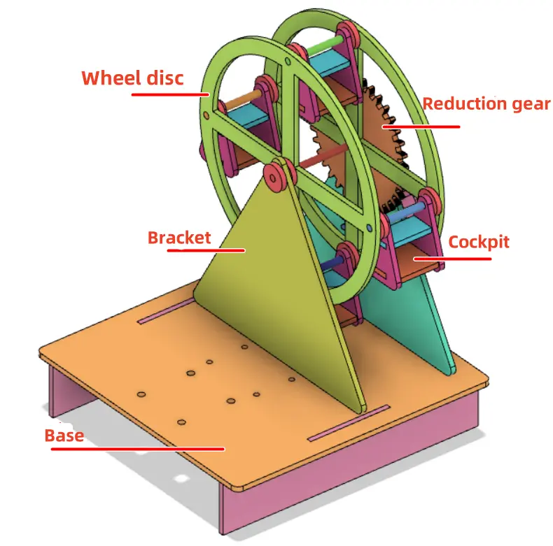
This project helps students understand how a rotating wheel, suspended cockpits, support brackets, a base, a reduction gear set, a TT motor, and remote-control components work together to create a moving Ferris wheel model.
| Item | Details |
|---|---|
| Project | Remote-control Happy Ferris Wheel model |
| Software | LaserMaker |
| Main Skills | Gallery graphics, TT Motor graphics, Triangle Tool, Rounded Corner Tool, Rectangle Tool, Modulus Gear tool, Distance Measuring Tool, Ellipse Tool, Offset Curve, Ring Array, tracing, cutting, wiring, and assembly |
| Suggested Material | Basswood laminate, 40 cm × 60 cm × 3 mm |
| Classroom Fit | Robotics and mechanism projects, gear transmission, amusement-ride modeling, laser cutting, remote-control structures, and engineering design activities |
Students will design a Ferris wheel with cockpits, wheels, a reduction gear set, support brackets, and a base. They will prepare the laser-cut parts in LaserMaker, set tracing and cutting processes, assemble the mechanical structure, connect the electronic components, and test whether the wheel rotates smoothly.
For teachers: Use this project to connect gear transmission, rotation speed, structural support, motor control, measurement, and laser-cut assembly.
For students: Use the activity to build a moving Ferris wheel model while learning how digital drawings become a working mechanical system.
For makerspaces: Use it as a more advanced powered model project that combines laser cutting, gears, wooden shafts, spacers, a TT motor, and remote-control components.
Analyze the structure of a Ferris wheel and identify the wheel, cockpit, bracket, base, power unit, and reduction gear set.
Use LaserMaker drawing and Gallery tools to create brackets, wheels, cockpits, gaskets, gears, and base parts.
Use the Modulus Gear tool to create a reduction gear set and adjust the motor shaft hole to fit the TT motor.
Measure clearance so the cockpits can rotate without hitting the base or bracket.
Set tracing and cutting processes, then assemble the model with wooden rods, spacers, screws, nuts, copper posts, receiver, battery, and motor.
Design thinking: Study a real Ferris wheel and simplify it into a classroom-scale model with clear parts and functions.
Computational thinking: Use dimensions, gear parameters, center distance, ring arrays, alignment, offsets, and spacing calculations to create accurate digital parts.
Engineering thinking: Consider rotation speed, gear meshing, axle clearance, cockpit balance, bracket spacing, base stability, and reliable powered motion.
Students should test powered and rotating parts carefully under teacher or lab supervisor guidance. Keep fingers, loose wires, and small parts away from gears, shafts, and the rotating wheel during testing.
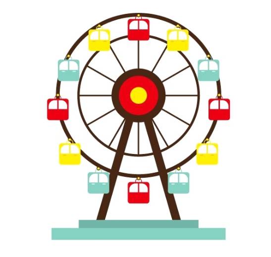
A Ferris wheel is a large wheel-shaped amusement ride with passenger cockpits hanging around the outer edge. As the wheel rotates slowly, the cockpits move to different heights and allow passengers to view the surroundings.
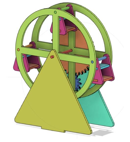
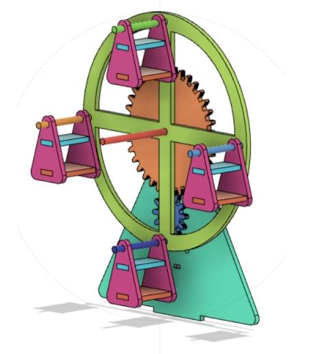
In this project, students create a simplified powered Ferris wheel. The rotating wheel carries four cockpits, the bracket supports the wheel, the base holds the structure, and the gear set helps reduce the wheel speed for smoother movement.
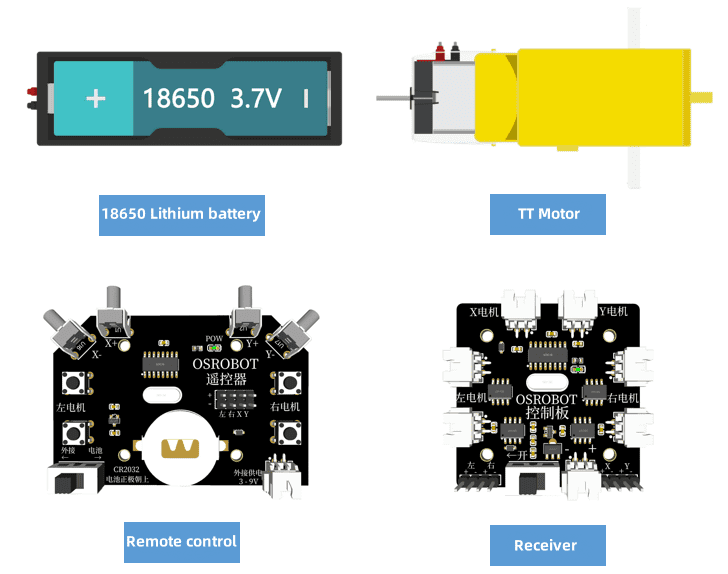
Before modeling the Ferris wheel, students should identify the electronic components, structural materials, axle material, and hardware used in the project.
| No. | Name | Quantity |
|---|---|---|
| 1 | 2.4G remote control with battery | 1 |
| 2 | 2.4G receiver | 1 |
| 3 | TT motor, 1:220 | 1 |
| 4 | 18650 battery with cable | 1 |
| 5 | Basswood laminate, 40 cm × 60 cm × 3 mm | 1 |
| 6 | M3 screws, nuts, and copper posts | Several |
| 7 | 4 mm wooden rods | Several |
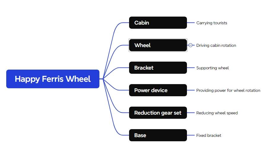
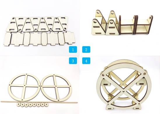
The Ferris wheel structure is organized into five main part groups: cockpits, wheels, reduction gear set, brackets, and chassis.
| Part Number | Part Name | Number of Parts | Function |
|---|---|---|---|
| 1 | Cockpit | 4 | Holds the passenger model area and hangs from the wheel |
| 2 | Wheel | 2 | Rotates and carries the cockpits |
| 3 | Reduction gear set | 1 | Reduces the rotation speed of the wheel |
| 4 | Bracket | 2 | Connects the wheel to the base and holds the motor |
| 5 | Chassis | 1 | Fixes the bracket, battery box, and receiver |
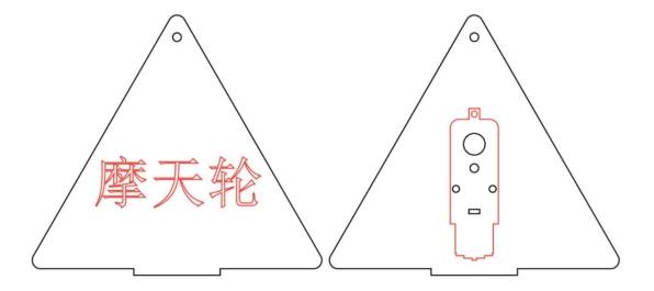
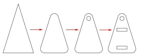
The bracket is a key support part for the Ferris wheel. In the source workflow, the bracket uses a triangular structure and the TT motor size helps determine its scale.
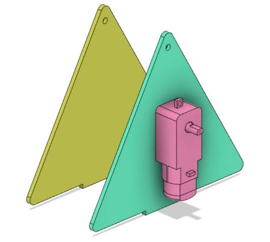
Open LaserMaker, choose the TT Motor graphic from Open Source Robotics Hardware in the Gallery, drag it onto the canvas, check its size, and group the motor graphics so they can be moved as one object.
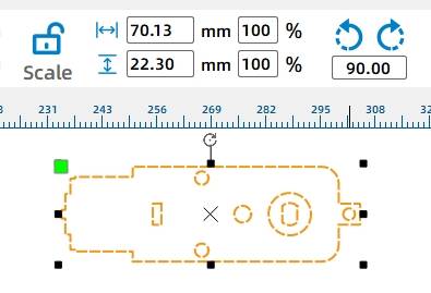
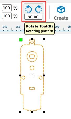
Select the TT motor graphic and rotate it by 270 degrees.
Drag a triangle from Basic Graphics, then adjust it to about 140 mm wide and 121.24 mm high. Use the Rounded Corner Tool with a 4 mm corner radius, place the TT motor on the bracket, and use horizontal center alignment to align the two parts.
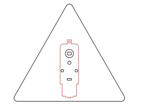
Use the Rectangle Tool to draw a 40 mm by 3 mm rectangle as the bracket tenon. Align the rectangle with the lower edge of the triangle, center it horizontally, then use the Union Tool to merge it with the triangle and create the bracket prototype.
A Ferris wheel usually rotates slowly for a comfortable experience. In this project, students reduce wheel speed by combining the motor with a reduction gear set.
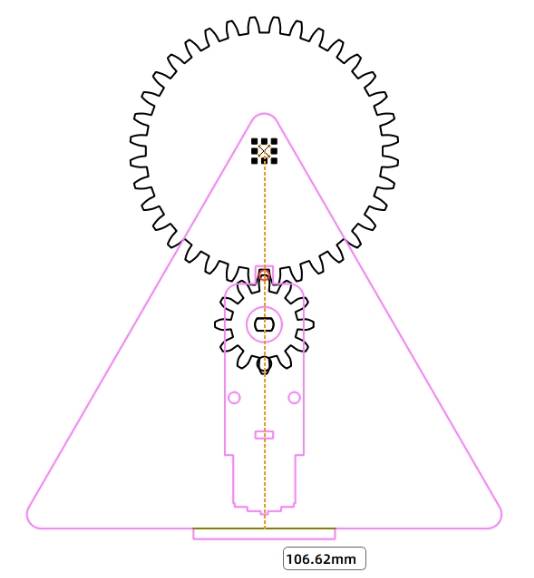
Use the Distance Measuring Tool to measure the distance from the center of the TT motor shaft to the top of the bracket. In the source workflow, the measured distance is 59.62 mm, but the actual value depends on the final motor position.
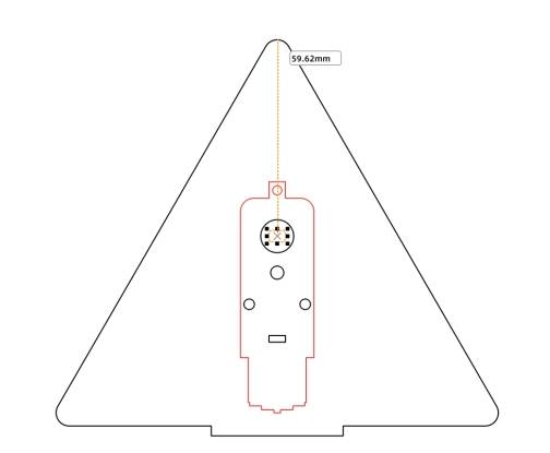
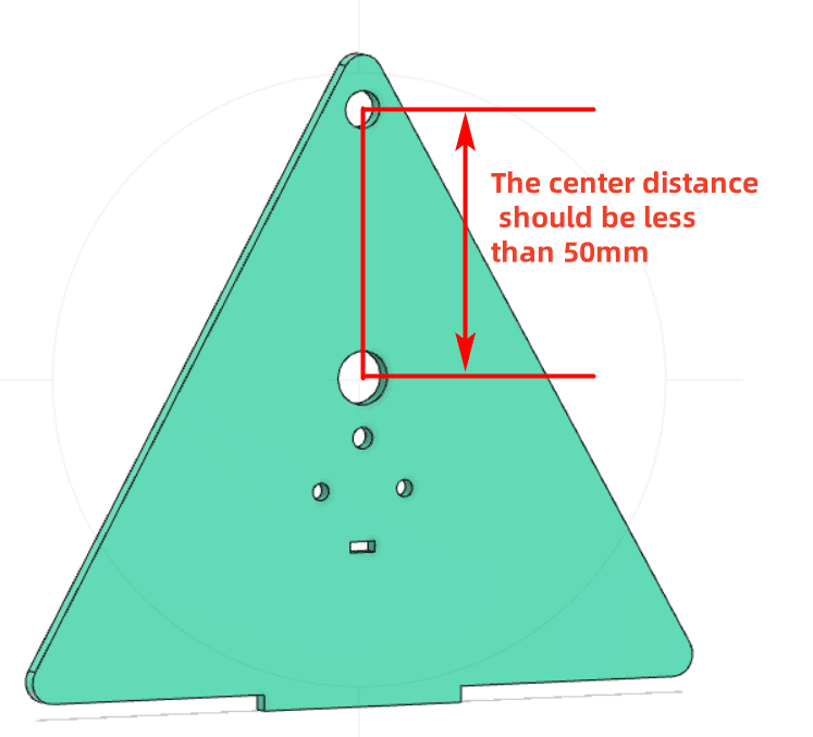
The wheel and gear axle use a 4 mm wooden rod. Because the axle should not sit too close to the upper edge of the bracket, the gear center distance should be less than 50 mm in this design.
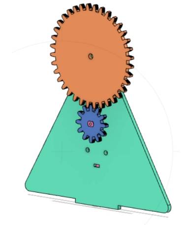
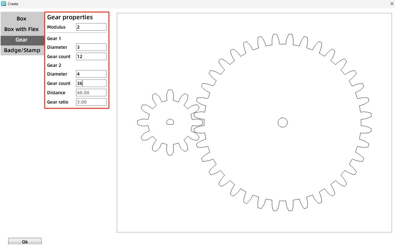
Open the Artifact tool and choose Modulus Gear. In the source workflow, the modulus is set to 2. Gear 1 uses a 3 mm bearing diameter and 12 teeth. Gear 2 uses a 4 mm bearing diameter and 36 teeth. The center distance is automatically confirmed as 48 mm.
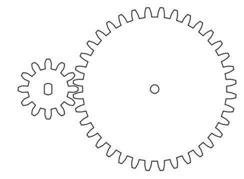
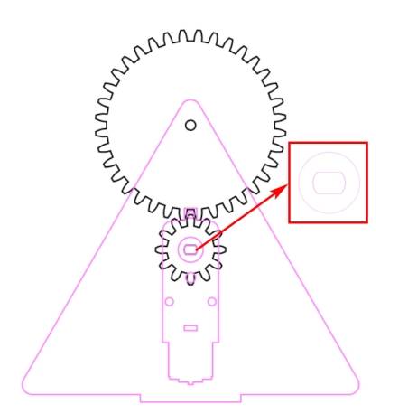
Because the TT motor shaft does not match the default D-shaped hole of the small gear, delete the D-shaped hole on Gear 1 and replace it with the TT Motor Hole graphic from the Gallery. Align it to the gear center. To reduce gear jamming caused by tight meshing, the source workflow moves Gear 1 left by 1 mm.
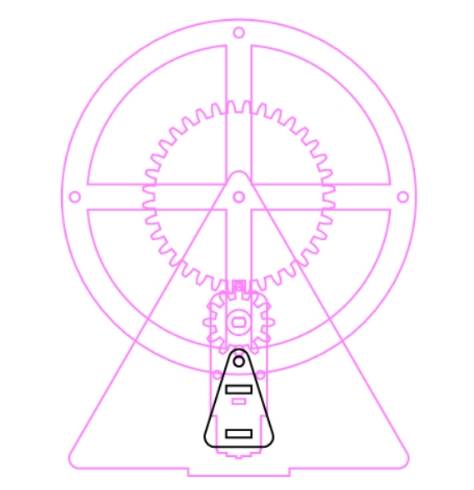
Select the two gears, rotate them by 270 degrees, and group them. Drag the gear set onto the bracket so the TT hole in the gear overlaps the TT hole on the bracket. The hole of Gear 2 can also be used as the 4 mm shaft hole on the bracket.
Copy the final bracket shapes. One bracket can include red text labeling, while the other bracket keeps the bracket outline, TT motor graphics, and shaft hole needed for assembly planning.
The wheel is the core rotating part of the Ferris wheel. It carries the cockpit axle holes and rotates around the main shaft.
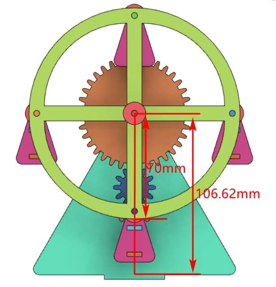
Before drawing the wheel and cockpits, measure the distance from the wheel shaft center to the lower edge of the bracket. Use an auxiliary line to support measurement. In the source workflow, this distance is 106.62 mm.
Based on the measured clearance, the source workflow sets the wheel radius to 70 mm, which gives a wheel diameter of 140 mm.
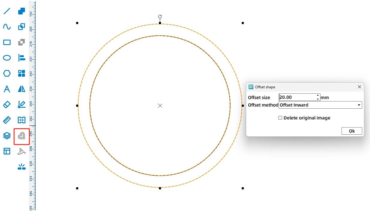
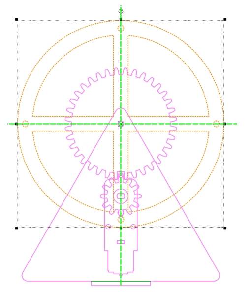
Use the Ellipse Tool to draw a 140 mm circle. Then use Offset Curve with a 20 mm inner offset to create a set of concentric circles.
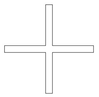
Use the Rectangle Tool to draw a 130 mm by 10 mm rectangle. Copy it, rotate the copy by 90 degrees, align the two rectangles to the center, and merge them to create a cross-shaped inner contour.
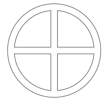
Center-align the cross shape with the concentric circles. Use Difference Set to create the prototype of the wheel, then set its coordinates to 300,100 in the source workflow.
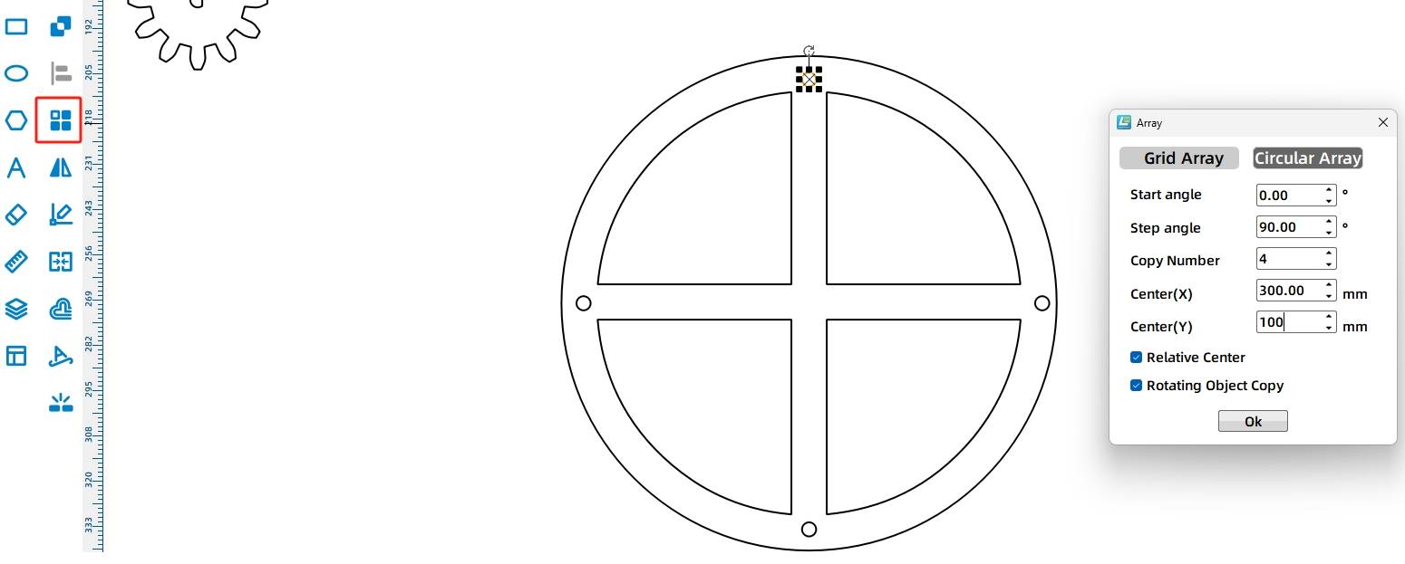
Draw a 4 mm diameter circle as a cockpit axle hole, place it near the upper edge of the wheel, and use Ring Array to create four holes. In the source workflow, the start angle is 0°, the step angle is 90°, the number of copies is 4, and the center point is 300,100. Group the finished wheel graphics.
Drag the wheel so its center aligns with the bracket axle hole. Because the bracket and wheel both use a 4 mm wooden rod, the 4 mm bracket axle hole can align with the wheel shaft position.
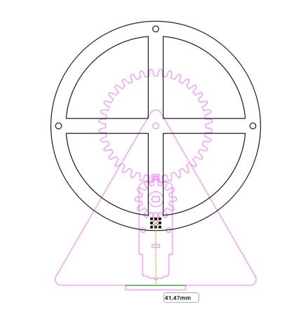
Measure the distance from the lowest cockpit hole on the wheel to the base. In the source workflow, this distance is 41.47 mm, so students should check the cockpit height carefully to avoid collision during rotation.
For the cockpit side, drag a triangle from Basic Graphics and set it to 30 mm wide and 48 mm high in the source workflow. Round the three corners with a 4 mm radius. Draw a 4 mm diameter circle as the axle hole, and draw two 10 mm by 3 mm rectangles as the roof and base connection slots.
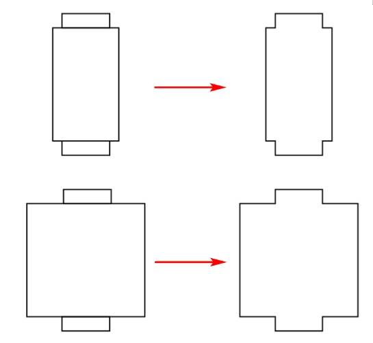
For the cockpit roof, draw a 14 mm by 24 mm rectangle and two 10.1 mm by 3 mm tenon rectangles. Align and merge the three rectangles to form the roof. For the cockpit base, draw a 25 mm by 24 mm rectangle and use the same tenon workflow.
Group the cockpit side graphics and align the cockpit axle hole with the wheel cockpit axle hole. Confirm that the cockpit does not touch the bottom when it reaches the lowest point.
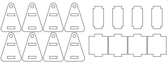
The final model uses four cockpits. Each cockpit includes two cockpit sides, one roof, and one base. Therefore, the final cockpit part set includes eight cockpit sides, four cockpit roofs, and four cockpit bases.
To help the Ferris wheel run smoothly, spacers are added between the wheel and bracket and between the wheel and cockpits. The source workflow uses 12 spacers for these positions, plus one additional spacer for the TT motor shaft and pinion gear connection.
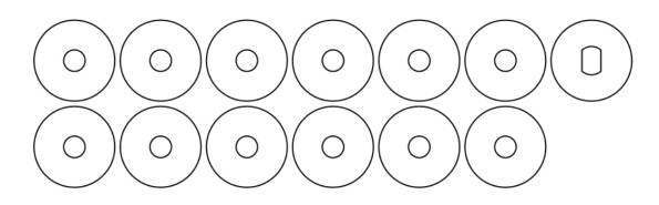
Use the Ellipse Tool to draw a 4 mm circle and a 15 mm circle. Center-align the two circles to create a ring-shaped spacer, then duplicate it to create 12 spacers. For the TT motor shaft spacer, draw a 15 mm circle and align it with a TT motor hole graphic from the Gallery.
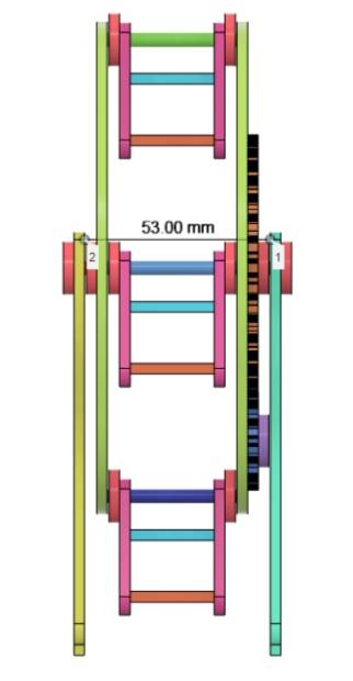
Before drawing the base, determine the bracket slot distance. In the source workflow, the theoretical spacing is calculated from cockpit width, spacers, wheels, gears, and gasket thicknesses. The bracket slot distance is set to 53 mm to allow smooth rotation.
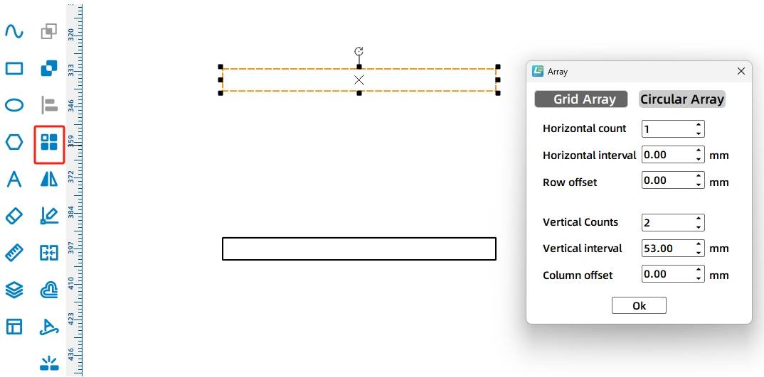
Draw a 39.5 mm by 3 mm rectangle as the bracket mortise. Use Rectangular Array with 1 horizontal copy, 2 vertical copies, 53 mm vertical spacing, and 0 mm offset to create two bracket slots.
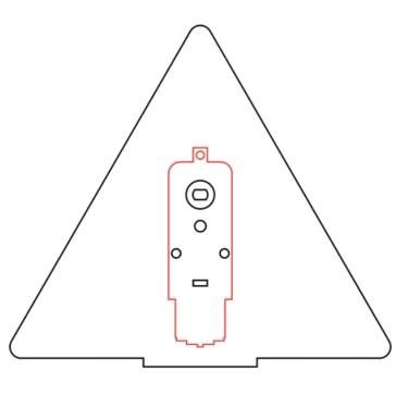
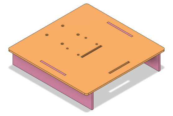
Plan the base platform for the brackets, 18650 battery, and OSROBOT control board. In the source workflow, the base platform is set to 160 mm by 160 mm with 4 mm rounded corners. Two 3 mm by 50 mm slots are added for the base brackets.
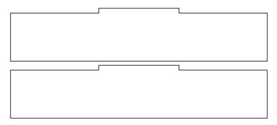
For the base bracket, draw a 160 mm by 30 mm rectangle and a 40 mm by 3 mm tenon rectangle. Align the tenon with the top edge of the base bracket and merge the shapes. Copy the finished bracket to create the second base bracket.
After all parts are complete, arrange the layout for laser processing.
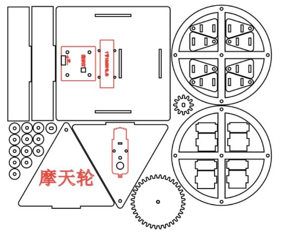
The Ferris wheel drawing uses two main processes: tracing and cutting. Red-layer objects are used for tracing details, and black-layer objects are cut through the material.
Tracing: Double-click the red block in the processing area. Select basswood plywood as the material, choose tracing line as the process, and set the processing thickness to 0.10.
Cutting: Double-click the black block in the processing area. Select basswood plywood as the material, choose cutting as the process, and set the processing thickness to 3.00.
Turn on the laser cutting machine and laser switch. When the start button becomes ready, upload the drawing to the laser cutting machine and begin cutting from the machine panel.
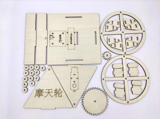
After cutting, identify the finished parts and prepare them for mechanical assembly.
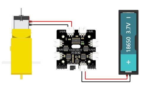
Connect the circuit according to the wiring diagram so the Ferris wheel can operate smoothly with the remote-control receiver, battery, and TT motor.
First, locate the cockpit parts and assemble the four cockpits.
Next, locate the wheel parts. Assemble the cockpits and wheel with 4 mm wooden rods and spacers. Use hot melt glue at the edge of each wooden rod near the wheel cockpit holes, while keeping a small gap between the two wheel disks and each cockpit so the cockpit can continue hanging downward as the wheel rotates.
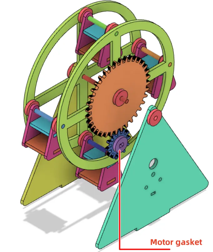
Then locate the reduction gear set, bracket, TT motor, and related hardware. Fix the TT motor to the bracket with screws and nuts. Install the spacer onto the TT motor shaft, then install the pinion gear onto the motor shaft.
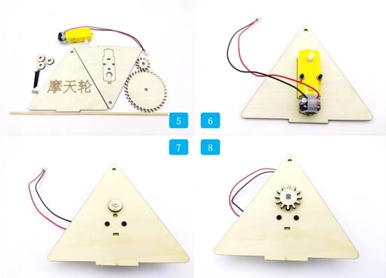
Align the large gear shaft hole with the wheel shaft hole and glue them together. Use a 4 mm wooden rod to connect the wheel disk to the bracket.
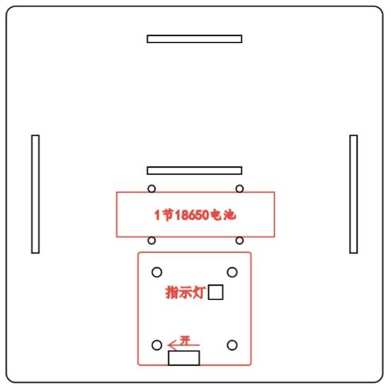
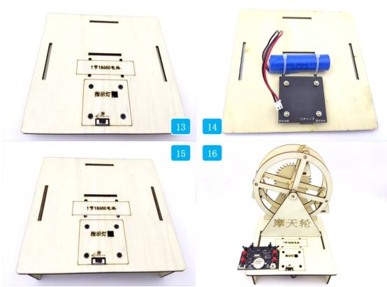
Locate the base, OSROBOT2 receiver board, copper posts, screws, nuts, and related parts. Fix the copper posts to the OSROBOT2 control board, then fix the control board to the base.
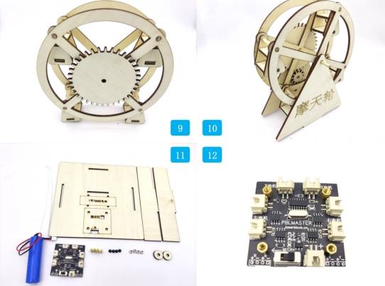
Secure the battery to the base bracket with ties, attach the base bracket, and fix the bracket to the base. Add spacers on both sides of the wheel axle and secure the axle with hot melt glue.
Check whether the wheel rotates smoothly without rubbing against the brackets or base.
Test whether the cockpits hang downward as the wheel rotates and do not collide with the base.
Confirm that the reduction gear set meshes smoothly and does not jam during motor operation.
Check whether the bracket spacing, shaft holes, spacers, and wooden rods are aligned correctly.
Review whether the receiver, battery, and wiring are fixed securely on the base before running the model.
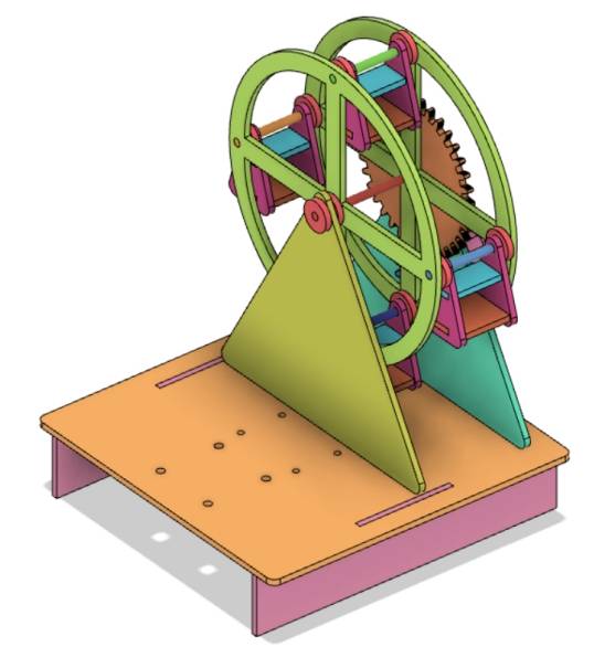
After design, laser processing, wiring, and assembly, students complete a remote-control Ferris wheel model. The project gives students hands-on experience with gear transmission, wheel structure, suspended cockpits, bracket design, base planning, laser cutting, and powered motion.
The Ferris wheel model in this lesson achieves the basic function of a rotating amusement-ride structure. As an extension challenge, students can increase the number of cockpits, explore additional gear stages to reduce rotation speed further, or redesign the bracket and base for improved stability and appearance.
This project is suitable for classroom laser cutters that support cutting and tracing of sheet materials for small robotics and mechanism projects. For schools, makerspaces, and beginner STEAM labs, projects like Ferris wheels, gear-driven models, rotating amusement-park structures, and remote-control mechanisms can be completed with a classroom laser cutter such as the Thunder Laser Bolt Series.
Teachers can choose the machine and material setup based on classroom space, project size, material thickness, gear fit, electronic components, and learning goals. The same LaserMaker workflow can also be adapted for other CO2 laser machines when students move on to larger moving models or more advanced gear-driven engineering projects.
Talk To Our Experts Now!
Please leave your contact information so that we can serve you better.
NEED HELP FINDING THE RIGHT SOLUTION?
Talk to our team for machine recommendations, application advice, and support based on your needs.

 Stable & Consistent MachinesUnlimited ApplicationRobust After-sales SupportFactory Direct Supply


