


Remote-Control Dazzling Light Box Laser Cutting Project for STEAM Classrooms
 2024-07-17
WHAT ARE YOU LOOKING FOR?
Search Across Products, Blog Posts, Support Content, And Resources.

Remote-Control Dazzling Light Box Laser Cutting Project for STEAM Classrooms
2024-07-17

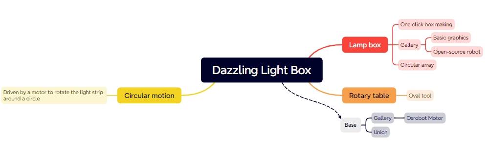
In this STEAM robotics and mechanism project, students design and build a remote-control dazzling light box using LaserMaker. The lesson connects box structure design, one-click box building, ring arrays, decorative light holes, TT motor mounting, LED light strings, 2.4G remote-control components, wiring, laser cutting, and hands-on assembly.
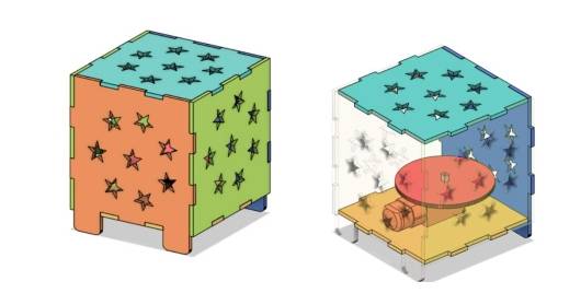
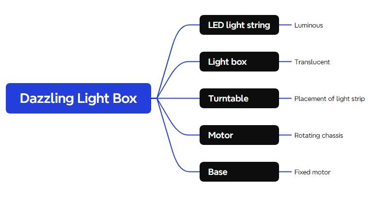
This project helps students turn a static laser-cut box into a powered light display. Students explore how a hollow box, rotating turntable, LED light string, motor, receiver, and battery work together to create a colorful night-time lighting effect.
| Item | Details |
|---|---|
| Project | Remote-control dazzling light box |
| Software | LaserMaker |
| Main Skills | One-Click Artifact, Right Angle Box, Gallery graphics, Ring Array, Grouping, Copy and Paste, Rectangle Tool, Union Tool, Distance Measuring Tool, Oval Tool, tracing, cutting, wiring, and assembly |
| Suggested Material | Basswood laminate, 40 cm × 60 cm × 3 mm |
| Classroom Fit | Robotics and mechanism projects, light box design, maker education, laser cutting, powered structures, and beginner remote-control activities |
Students will design a square light box with decorative light-transmission holes, add motor mounting features, create support feet, draw a rotating turntable for the LED light string, laser cut the parts, wire the control components, and assemble a powered light box that can create a dynamic lighting display.
For teachers: Use this project to connect box structures, digital pattern arrays, motorized movement, lighting design, wiring, and product-style assembly.
For students: Use the activity to build a colorful light box while learning how flat laser-cut panels can become a powered three-dimensional display.
For makerspaces: Use it as an introductory project that combines laser cutting, LEDs, a TT motor, and remote-control components.
Use LaserMaker One-Click Artifact to generate a right-angle box layout with mortise-and-tenon edges.
Create decorative light-transmission patterns with Gallery graphics and Ring Array.
Add motor mounting graphics, a threading hole, support feet, and a turntable for the LED light string.
Set tracing and cutting processes for motor reference marks, holes, box panels, support feet, and turntable parts.
Assemble the light box and connect the TT motor, 2.4G receiver, battery, and LED light string.
Design thinking: Turn the idea of a lantern or playground light feature into a laser-cut box with decorative holes and a dynamic lighting effect.
Computational thinking: Use dimensions, box-generation settings, ring array parameters, grouping, copying, and layer planning to prepare a clean digital model.
Engineering thinking: Consider motor placement, turntable radius, LED position, wire routing, box stability, support feet, and ease of opening the light box.
Students should test powered parts carefully and follow teacher or lab supervisor instructions when working with batteries, receivers, motors, LEDs, and moving components. The light box should be assembled so wires are protected and rotating parts do not rub against the box panels.
Light boxes and lantern-style displays are often used in playgrounds, festivals, classrooms, and maker events to create a bright visual atmosphere. When decorative holes are cut into the box, light can pass through and project patterns onto the surrounding space.
In this project, students add a rotating motor inside the box so the LED light string can move and create a changing light effect. The result is a small powered display that combines structure, light, motion, and control.

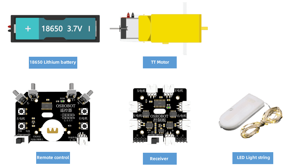
Before modeling the light box, students should identify the electronic components, structural material, lighting component, and hardware used in the project.
| No. | Name | Quantity |
|---|---|---|
| 1 | 2.4G remote control with battery | 1 |
| 2 | 2.4G receiver | 1 |
| 3 | TT motor, 1:120 | 1 |
| 4 | 18650 battery with cable | 1 |
| 5 | Basswood laminate, 40 cm × 60 cm × 3 mm | 1 |
| 6 | M3 screws and nuts | Several |
| 7 | LED light string | 1 |
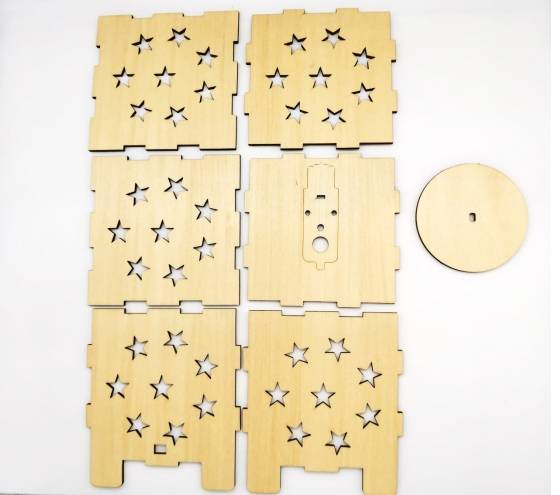
The laser-cut structure is organized into the light box panels, chassis, and LED light-string turntable.
| Part Number | Part Name | Number of Parts | Function |
|---|---|---|---|
| 1 | Light box panels | 6 | Display light through decorative openings |
| 2 | Chassis | 1 | Fix the motor and support the box |
| 3 | Turntable | 1 | Hold the LED light string and rotate with the TT motor |
Open LaserMaker and click One-Click Artifact from the menu bar. This tool can quickly generate the flat layout of a box structure, which saves time compared with drawing each panel and joint manually.

In the pop-up window, choose the Right Angle Box tool. In the source workflow, the box length, width, and height are each set to 100 mm, and the notch size is set to 15 mm. Preview the flat display map before creating the box.
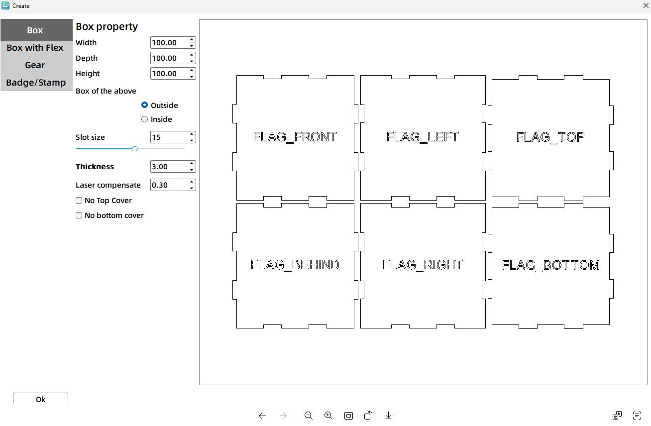
Tool Tip: The notch size is the mortise-and-tenon length in the box layout. In the source workflow, the laser compensation setting means the actual generated tenon length is about 14.4 mm when the notch size is set to 15 mm.
Click OK to generate the six box panels in the drawing area. The generated panels include orientation labels, which are useful during design and assembly.
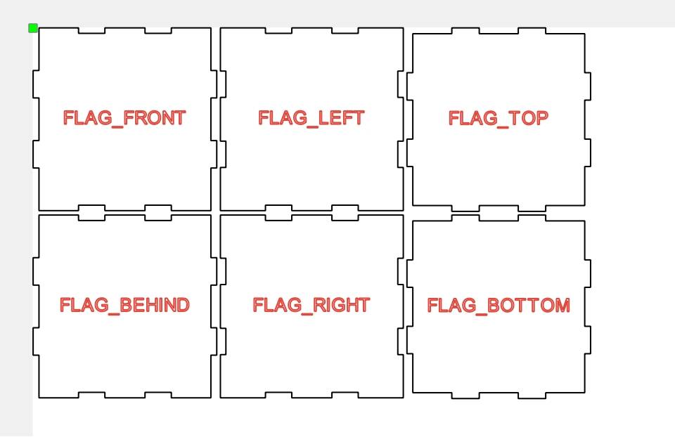
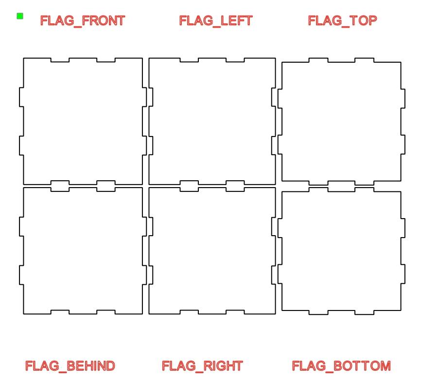
Move the orientation labels outside the panels so the center areas remain clear for decorative patterns and light-transmission holes.
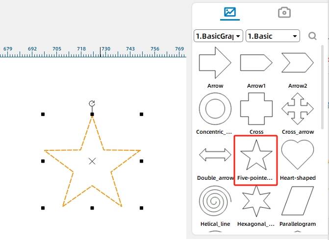
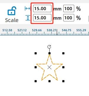
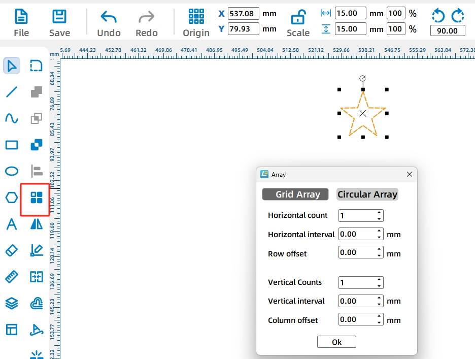
Open the Gallery panel and choose the Pentagram graphic from Basic Graphics. Drag it onto the canvas and resize it to 15 mm by 15 mm.
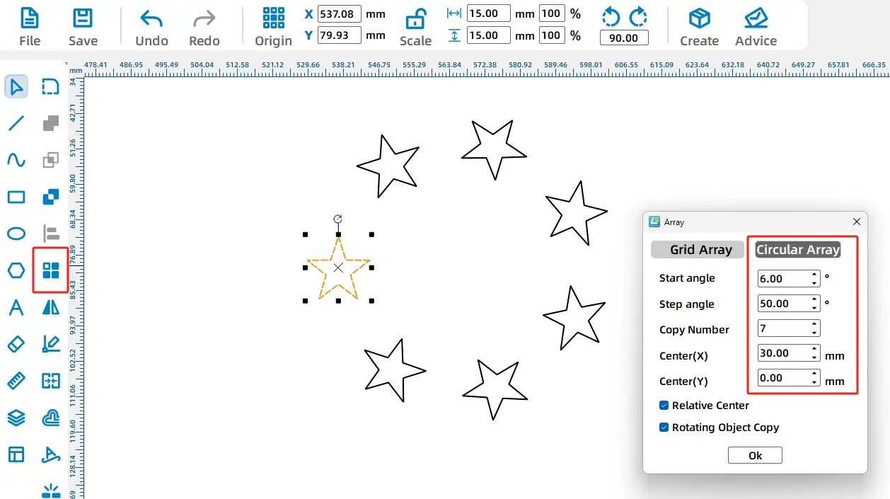
Select the pentagram and open the Ring Array tool from Advanced Tools. The array preview helps students create repeated star patterns around a center point.
In the source workflow, the Ring Array settings are Start Angle 6°, Step Angle 50°, Number of Copies 7, and Center X 30. These settings create a circular star pattern.
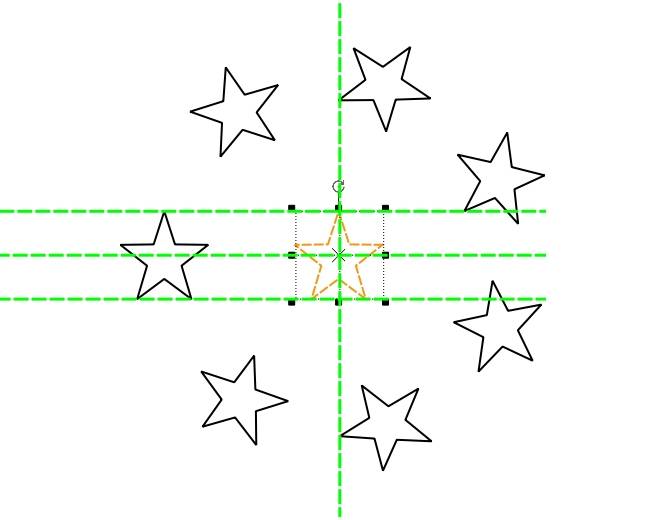
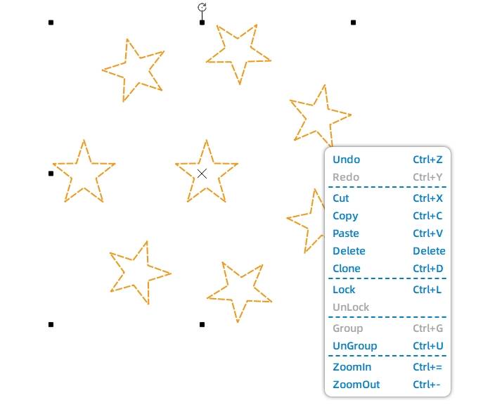
Add another pentagram to the center of the circular star pattern, then group the star graphics together so they can be copied and positioned as one pattern.
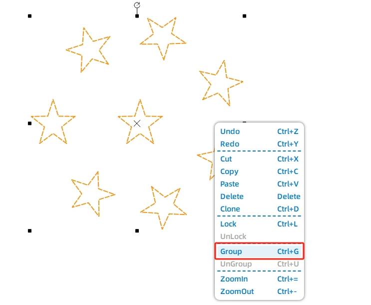
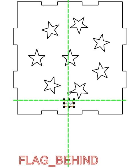
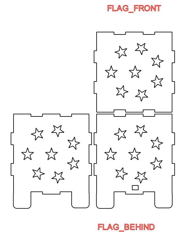
Use Copy and Paste to duplicate the grouped star pattern, then place the patterns onto the light box panels.
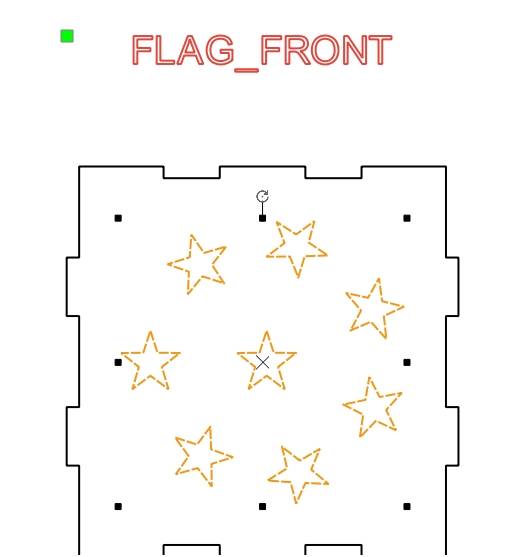
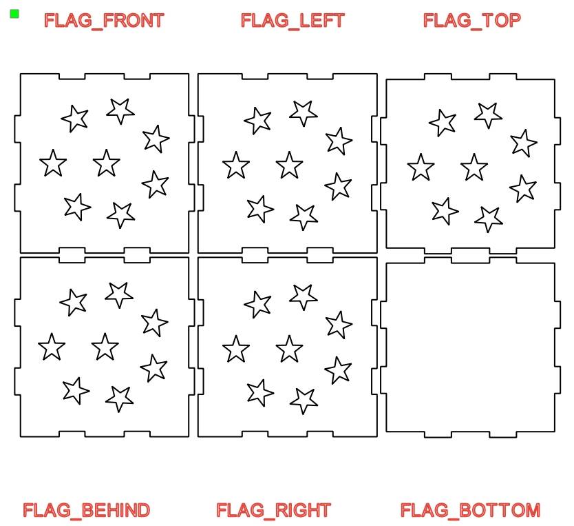
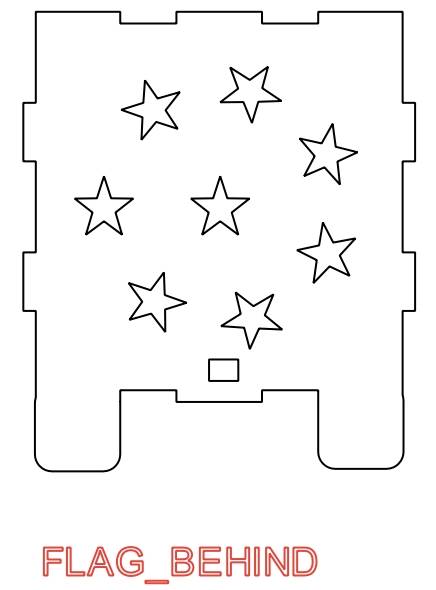
Place the star patterns on the front panel and other visible panels. The lower panel is used for motor installation, so it does not need the circular star pattern.
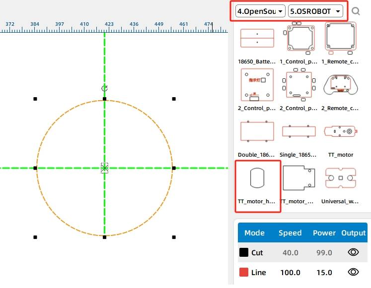
Open the Open Source Robotics section in the Gallery and select the OSROBOT motor graphic. Drag it onto the canvas so the motor mounting holes can be added to the lower panel.
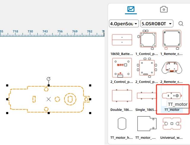
Rotate the motor graphic by 90 degrees so the TT motor is positioned vertically in the design.
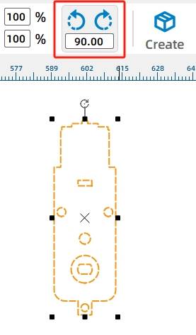
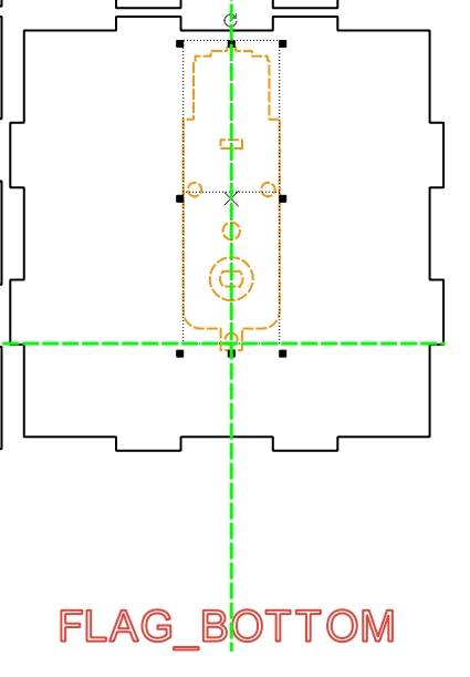
Move the motor graphic onto the lower panel. The motor shaft hole should be placed as close as practical to the center of the lower panel so the LED turntable has enough space to rotate inside the light box.
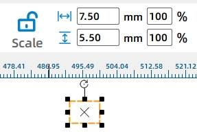
Because the receiver and battery are outside the light box in the source workflow, draw a small threading hole on the rear panel. In the source workflow, the hole is a 7.5 mm by 5.5 mm rectangle.
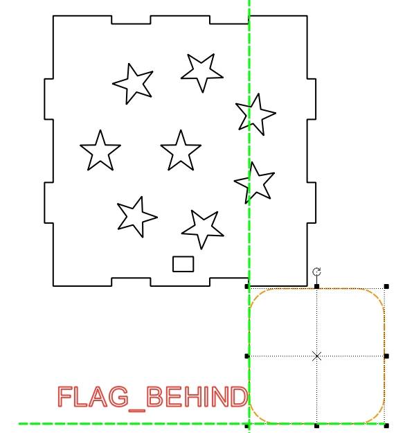
The motor and hardware create extra height under the light box, so support feet are added to improve stability. Select a rounded rectangle from the Basic Graphics section of the Gallery.
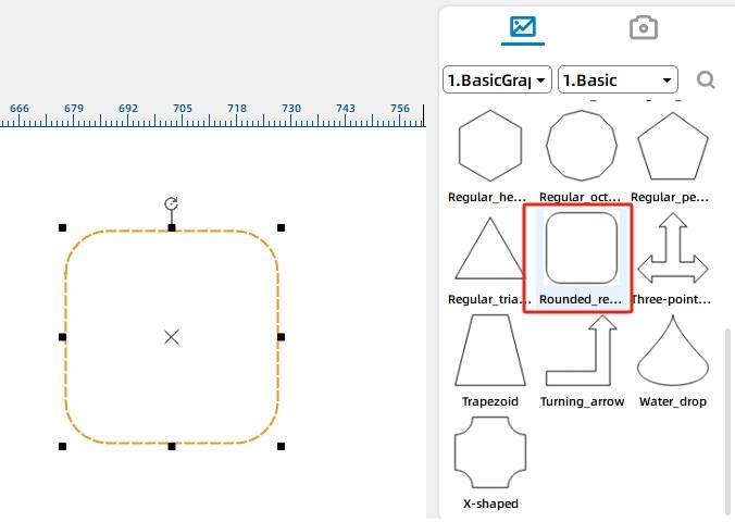
Place the rounded rectangle at the lower right side of the rear panel and resize it so its width matches the nearby tenon area.
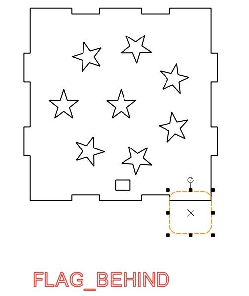
Copy and paste the second rounded rectangle, then place it at the lower left side of the rear panel.
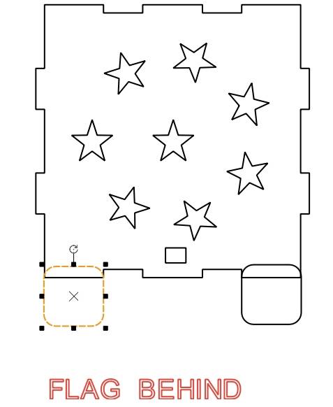
Select the rear panel and the two rounded rectangles, then use the Union Tool to merge them into one connected part.
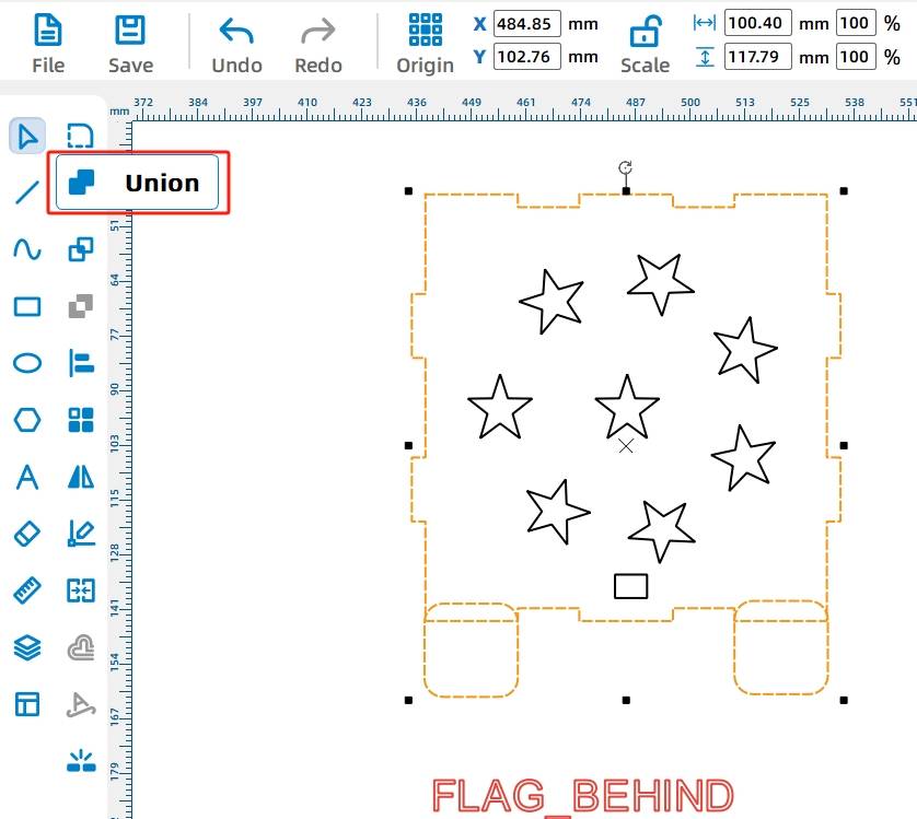
The front and rear panel tenon structures match, so students can repeat the same process for the front panel or copy the rear panel, remove the threading hole, and use it as the front panel with support feet.
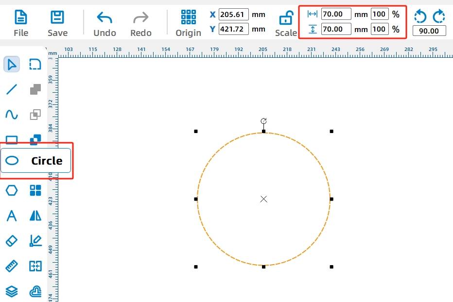
The LED light string sits on a round turntable attached to the TT motor shaft. Use the Distance Measuring Tool to estimate the available radius inside the light box. In the source workflow, the turntable radius is set to 35 mm, so the circle diameter is 70 mm.
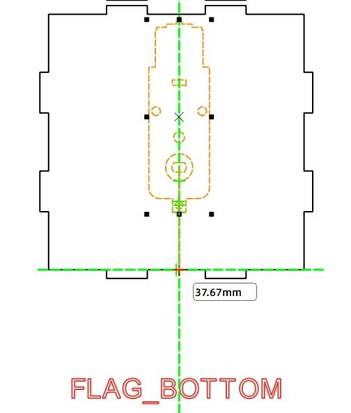
Use the Oval Tool and hold Ctrl to draw a 70 mm diameter circle for the turntable.
Add the TT motor shaft hole by selecting TT holes from Mechanical Parts in the Gallery and placing the graphic at the center of the turntable.
Delete any auxiliary labels, red text, or construction lines that are no longer needed, then save the file.
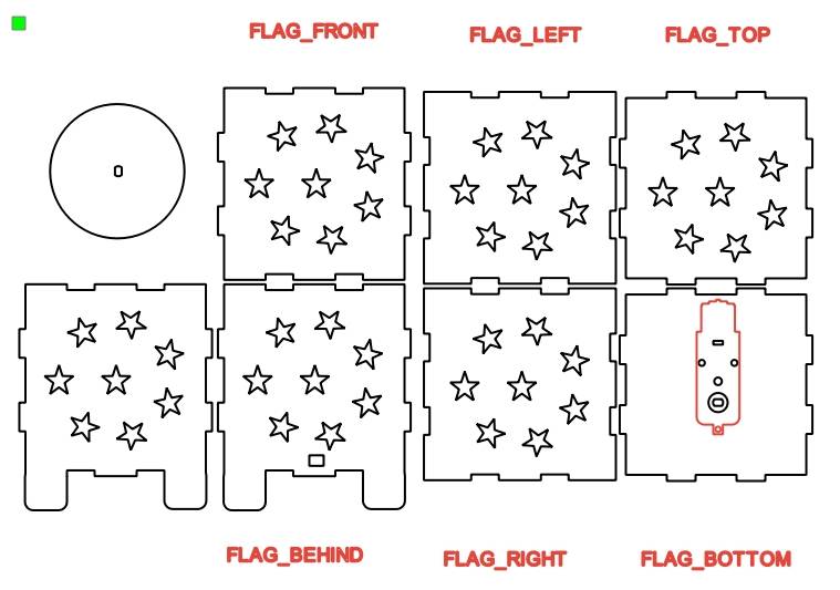
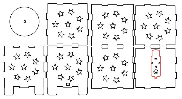
The light box drawing uses two main processes: tracing and cutting. In the source workflow, the OSROBOT motor outline is used for tracing, while the remaining structural parts, holes, decorative openings, and turntable are cut.
Before fabrication, students should check the speed and power settings for the selected laser cutting machine, simulate the process sequence, and confirm that tracing happens before cutting where needed.
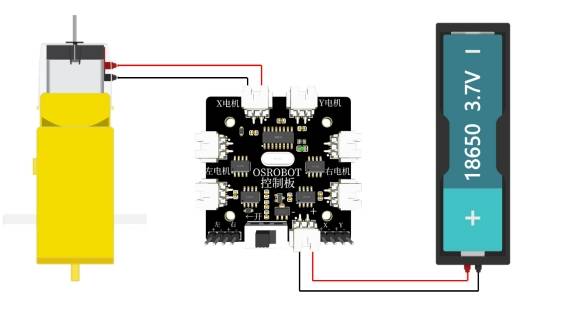
Before assembly, review the wiring diagram. The TT motor, 18650 battery, 2.4G receiver, and LED light string should be connected according to the project wiring plan.
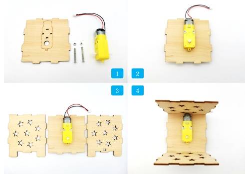
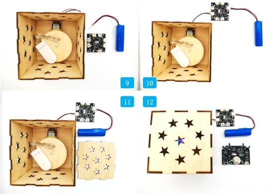
First, locate the motor, chassis, and matching hardware. Use screws and nuts to fix the motor to the chassis.
Then locate the front and rear panels of the light box. Assemble the front and rear panels with the chassis, and pass the TT motor connecting wires through the rear panel threading hole.
Next, locate the left and right panels and assemble them to the base plate. Then find the turntable and LED light string. Fix the turntable to the TT motor shaft and place the LED light string on the turntable.
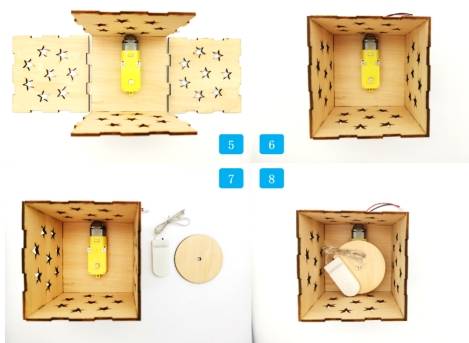
Locate the 18650 battery and 2.4G receiver. Connect the TT motor and battery to the receiver. Finally, locate the upper panel, turn on the LED string switch, and cover the upper panel.
After assembly, debug the light box by checking the lighting effect, rotation, wiring, and box stability.

Check whether the LED light string rotates smoothly on the turntable without hitting the box walls.
Confirm that the TT motor is mounted securely and close to the center of the lower panel.
Test whether the support feet keep the light box stable when the motor and screws are installed underneath.
Review whether the star-shaped holes allow enough light through while keeping the panels strong.
Check whether the wire hole is large enough for safe cable routing but not so large that it weakens the rear panel.
After modeling, laser processing, wiring, and assembly, students complete a remote-control dazzling light box. The project gives students a full design-to-fabrication experience, including ring arrays, one-click box building, Gallery graphics, graphic resizing, support-foot design, laser cutting, circuit wiring, and assembly testing.
In the finished light box, controlling the brightness of the LED light string may require opening the box frequently. At the same time, laser compensation and tight finger-joint fit can make repeated opening more difficult.
As an extension challenge, students can redesign the light box with a removable cover, a gift-box-style opening, a more accessible switch position, or a new pattern system that creates more colorful light effects.
This project is suitable for classroom laser cutters that support cutting and tracing of sheet materials for small robotics and mechanism projects. For schools, makerspaces, and beginner STEAM labs, projects like dazzling light boxes, LED displays, motorized turntables, and remote-control structures can be completed with a classroom laser cutter such as the Thunder Laser Bolt Series.
Teachers can choose the machine and material setup based on classroom space, material thickness, electronic components, and project size. The same LaserMaker workflow can also be adapted for other CO2 laser machines when students move on to larger light boxes or more advanced powered display projects.
Talk To Our Experts Now!
Please leave your contact information so that we can serve you better.
NEED HELP FINDING THE RIGHT SOLUTION?
Talk to our team for machine recommendations, application advice, and support based on your needs.

 Stable & Consistent MachinesUnlimited ApplicationRobust After-sales SupportFactory Direct Supply


