


Remote-Control Carousel Laser Cutting Project for STEAM Classrooms
 2024-07-19
WHAT ARE YOU LOOKING FOR?
Search Across Products, Blog Posts, Support Content, And Resources.

Remote-Control Carousel Laser Cutting Project for STEAM Classrooms
2024-07-19

In this STEAM robotics and mechanism project, students design and build a remote-control carousel using LaserMaker. The lesson connects carousel structure, horse-seat design, turntable rotation, TT motor mounting, 2.4G remote-control components, laser cutting, tracing, wiring, and hands-on assembly.
This project helps students understand how a rotating amusement-park ride can be simplified into a laser-cut classroom model. Students design the horse seats, turntable, and base, then add a motor and receiver so the carousel can rotate.
| Item | Details |
|---|---|
| Project | Remote-control carousel model |
| Software | LaserMaker |
| Main Skills | Gallery graphics, Rectangle Tool, Ellipse Tool, Eraser Tool, Rounded Corner Tool, Rectangular Array, grouping, rotation, alignment, tracing, cutting, wiring, and assembly |
| Suggested Material | Basswood laminate, 40 cm × 60 cm × 3 mm |
| Classroom Fit | Robotics and mechanism projects, maker education, motorized structures, amusement-park design, laser cutting, and beginner remote-control activities |
Students will design a carousel with four horse seats, one rotating turntable, and one base. They will prepare the laser-cut parts in LaserMaker, set tracing and cutting processes, connect the motor and receiver, and assemble the model so the carousel can rotate.
For teachers: Use this project to connect digital design, rotation, motor control, part alignment, and structural assembly.
For students: Use the activity to build a small moving carousel and understand how flat laser-cut parts can become a powered model.
For makerspaces: Use it as an introductory remote-control mechanism project before students move on to more complex moving structures.
Create carousel horse seats using Gallery graphics, rectangles, erasing, tracing, rounding, and arrays.
Design a rotating turntable with four mortise slots and a central TT motor hole.
Create a base that supports the TT motor, receiver, battery, and mounting holes.
Use LaserMaker alignment, grouping, rotation, and Rectangular Array tools to organize repeated parts accurately.
Set tracing and cutting parameters, then assemble and wire a powered carousel model.
Design thinking: Observe a real carousel and simplify it into horse seats, a rotating platform, a base, and control components.
Computational thinking: Use measurements, arrays, rotation angles, alignment tools, and layer settings to create a precise digital model.
Engineering thinking: Consider motor placement, center alignment, slot fit, turntable balance, base stability, and reliable rotation.
Students should test motorized parts carefully and follow teacher or lab supervisor instructions when wiring batteries, receivers, motors, and moving structures. Keep fingers, loose parts, and cables away from the rotating turntable during testing.
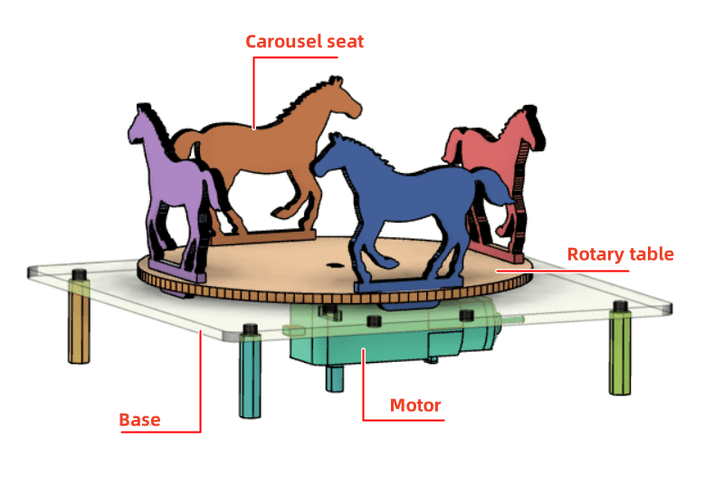
A carousel is an amusement-park ride where seats move around a central rotating platform. Riders usually sit on decorative horses or other themed seats while the carousel rotates.
In this project, students create a simplified carousel model. The horse seats are inserted into the turntable, and the TT motor installed in the base provides the rotation.

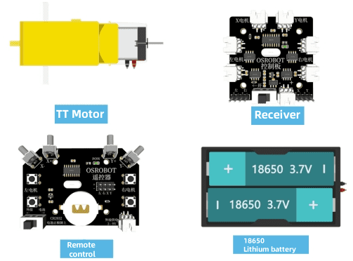
Before modeling the carousel, students should identify the electronic components, structural materials, and hardware used in the project.
| Number | Name | Quantity |
|---|---|---|
| 1 | 2.4G remote control with batteries | 1 |
| 2 | 2.4G receiver | 1 |
| 3 | TT motor, 1:120 | 1 |
| 4 | 18650 battery with cable | 1 |
| 5 | Basswood laminate, 40 cm × 60 cm × 3 mm | 1 |
| 6 | M3/M4 screws and nuts | 1 set |
| 7 | Additional 2.4G remote-control components, as listed in the source lesson | As needed |
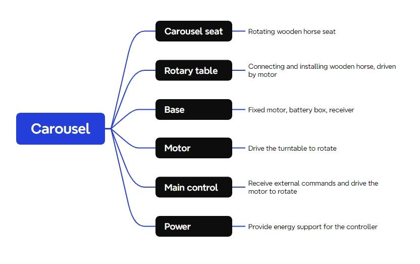
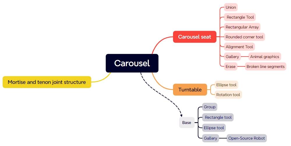
The carousel structure is organized into three main part groups: horse seats, turntable, and base.
| Part Number | Part Name | Quantity | Function |
|---|---|---|---|
| 1 | Carousel horse seat | 4 | Seat structures installed on the turntable |
| 2 | Turntable | 1 | Connects the horse seats and rotates with motor power |
| 3 | Base | 1 | Holds the motor, battery, and receiver |
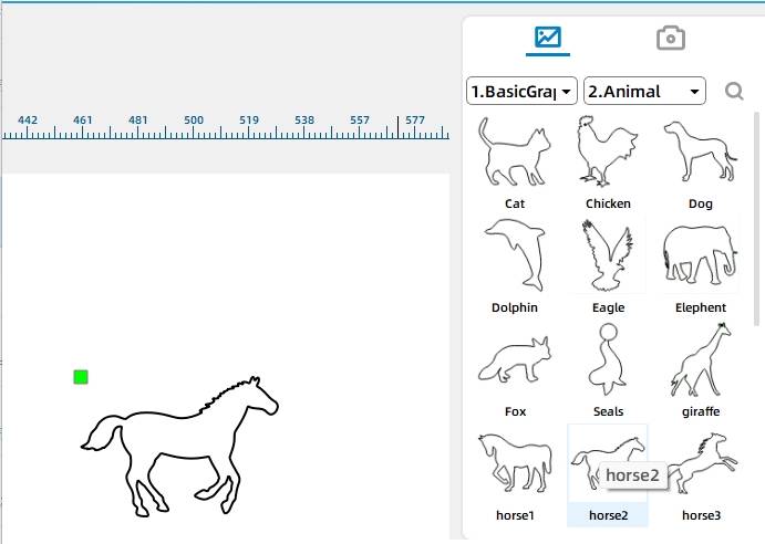
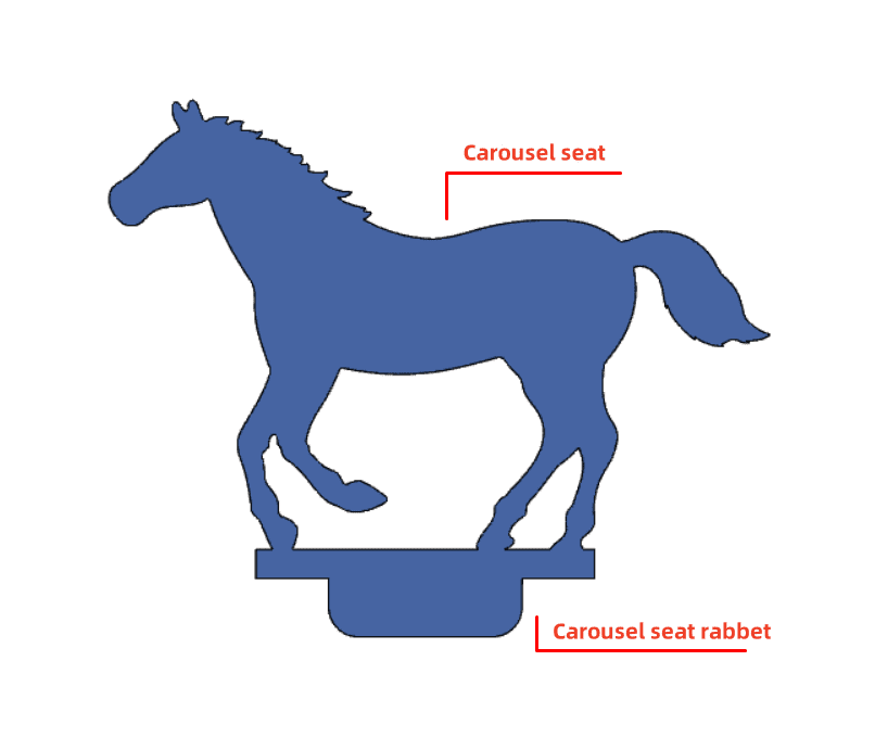
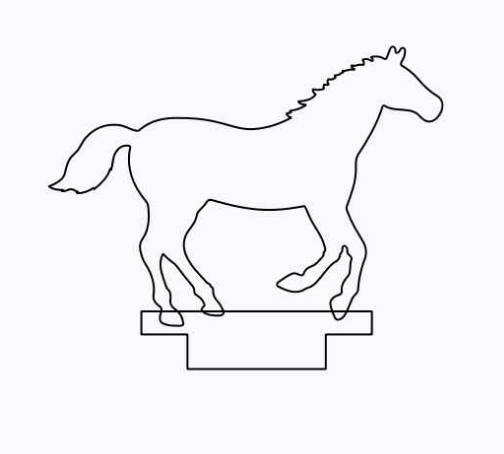
Open the Gallery panel in LaserMaker. Under Animal Graphics, select the Horse 2 graphic and drag it into the drawing area as the carousel horse seat.
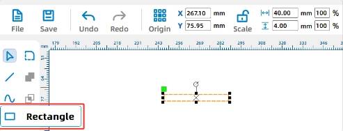
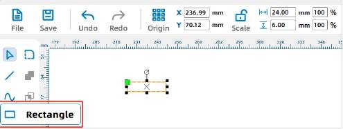
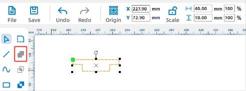
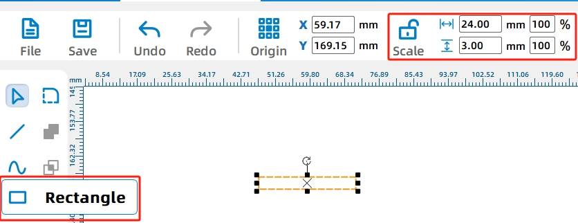
The horse graphic needs a base tenon so it can be inserted into the turntable. Draw two rectangles to create the tenon base. In the source workflow, the first rectangle is 40 mm wide and 4 mm high, and the second rectangle is 24 mm wide and 6 mm high.
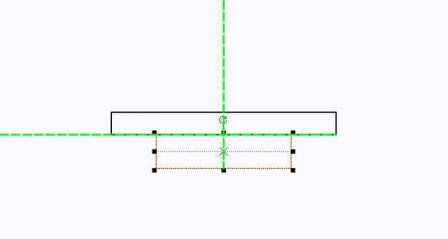
Center the two rectangles horizontally, then use the Union Tool to merge them into one tenon base.
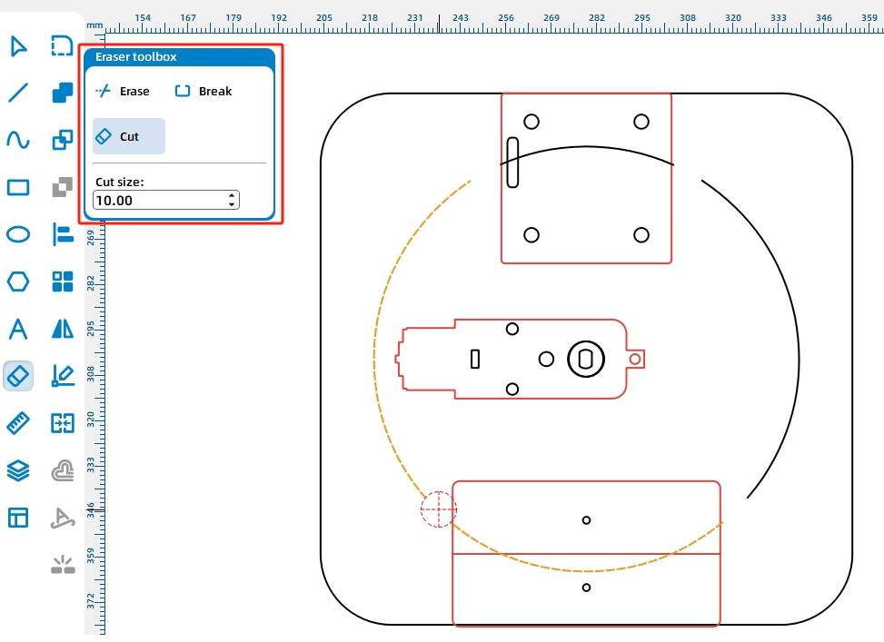
Move the tenon base so it overlaps with the Horse 2 graphic. Because overlapping cut lines may separate the horse from the tenon during laser cutting, use the Eraser Tool to remove unwanted intersecting line segments.
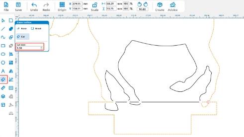
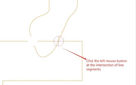
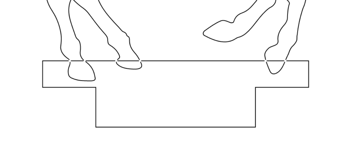
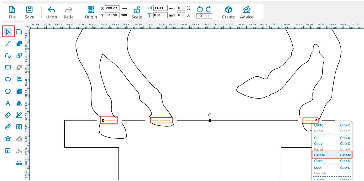
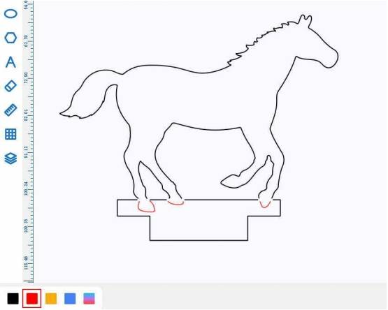
Delete the remaining unwanted line segments. If the horseshoe shape should be visible but not cut through, select the horseshoe graphics and assign them to the red tracing layer.
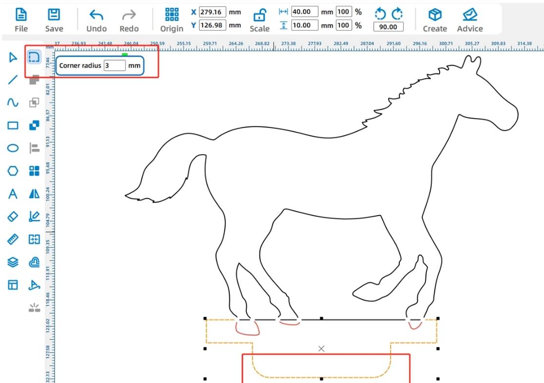
Round the lower corners of the horse-seat tenon with a 3 mm radius so it is easier to insert into the turntable slots.
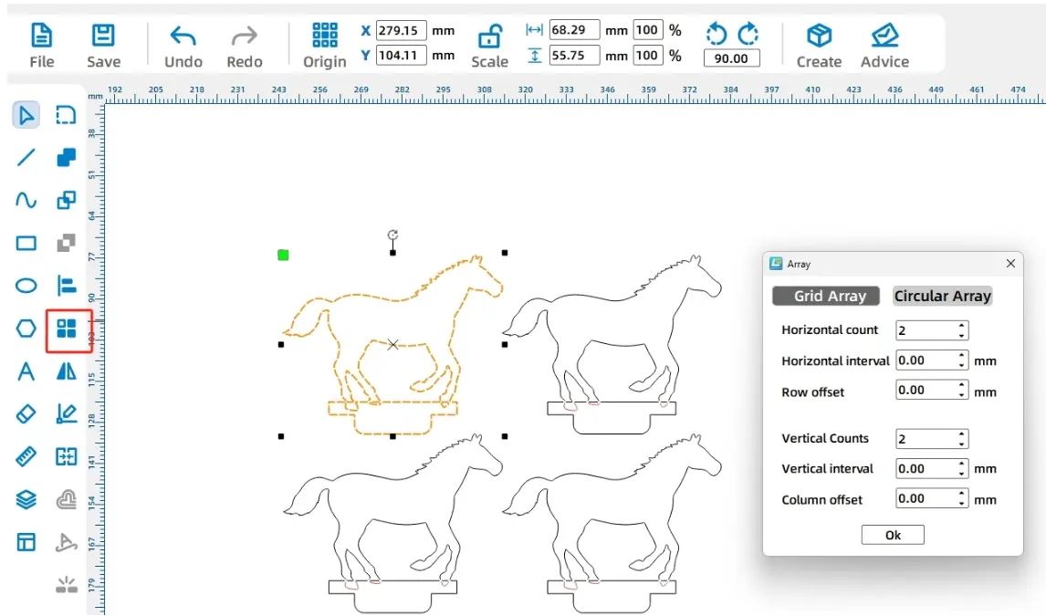
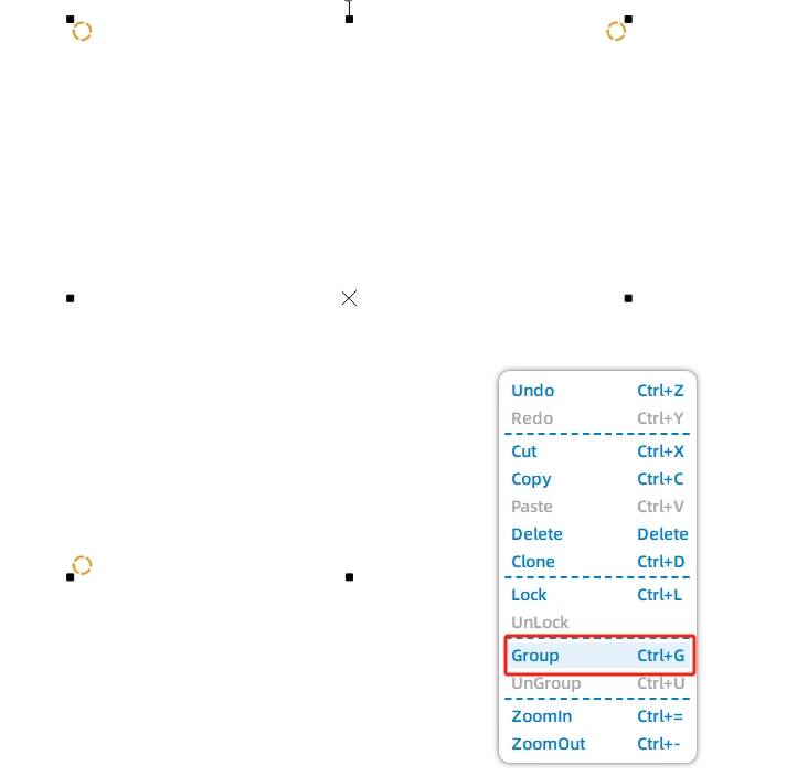
The carousel uses four horse seats. Select the completed horse-seat graphic and use Rectangular Array to create a 2 by 2 layout.
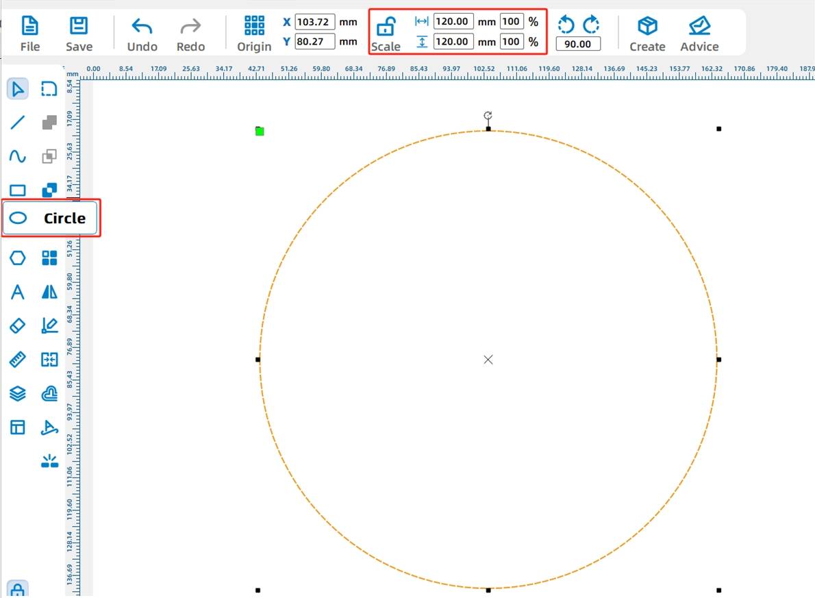
Use the Ellipse Tool to draw a circle and set its width and height to 100 mm. This circle becomes the rotating turntable.
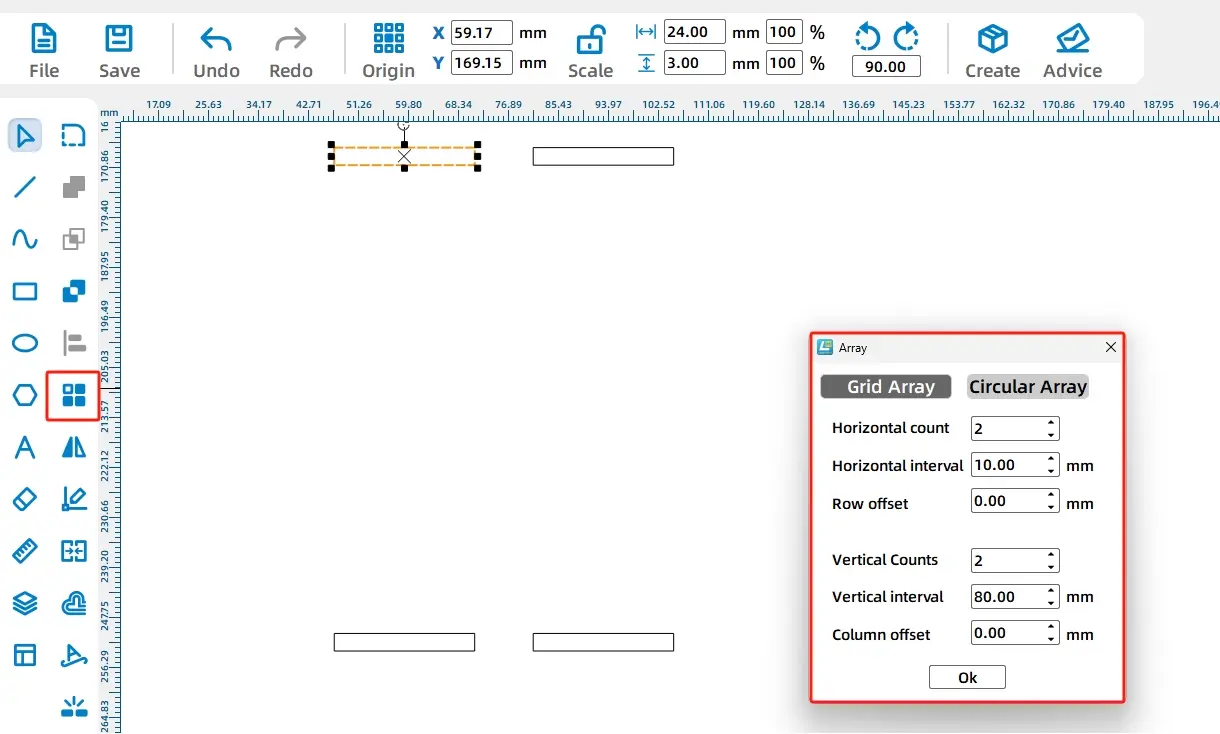
Draw a rectangular slot for the horse-seat tenon. In the source workflow, the slot is 24 mm wide and 3 mm high. Then use Rectangular Array to create four identical slots.
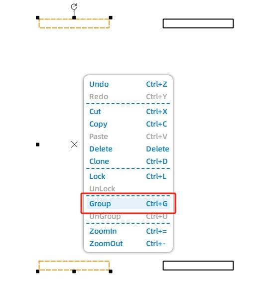
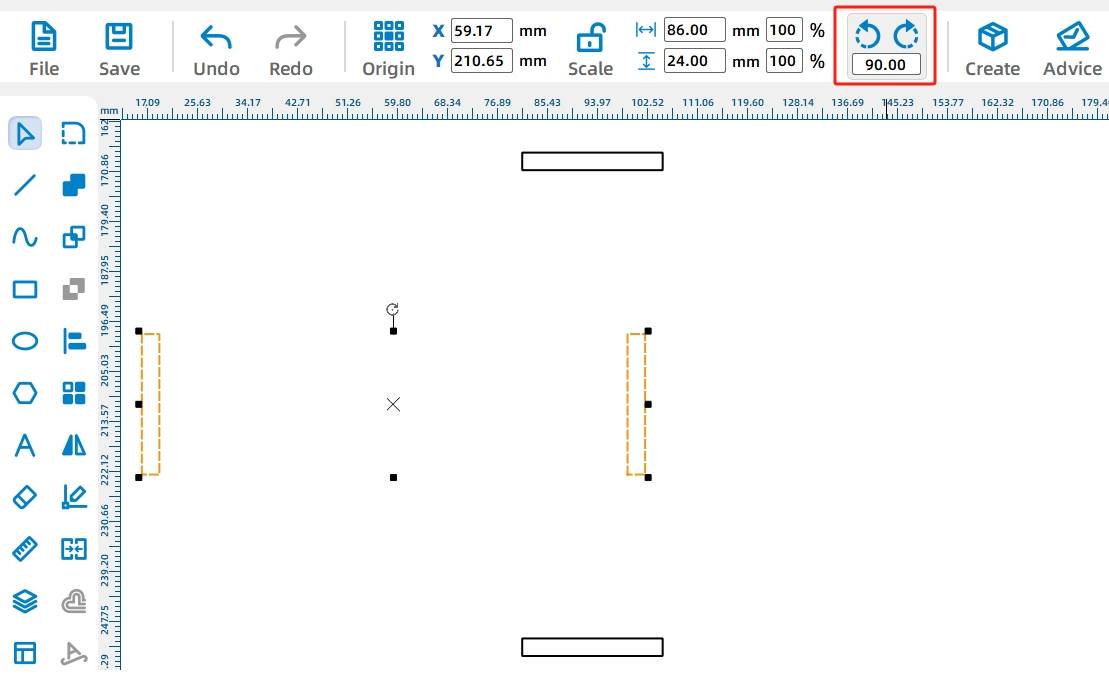
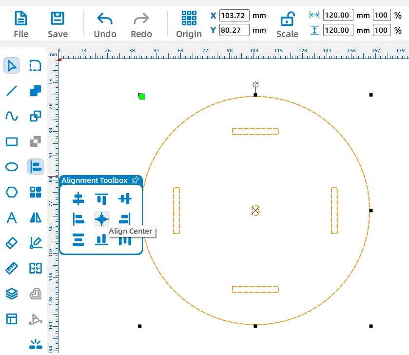
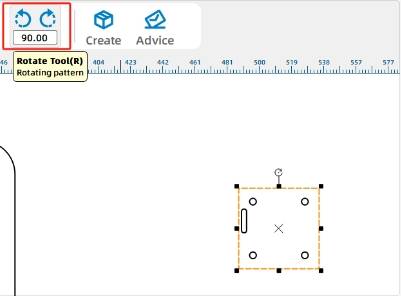
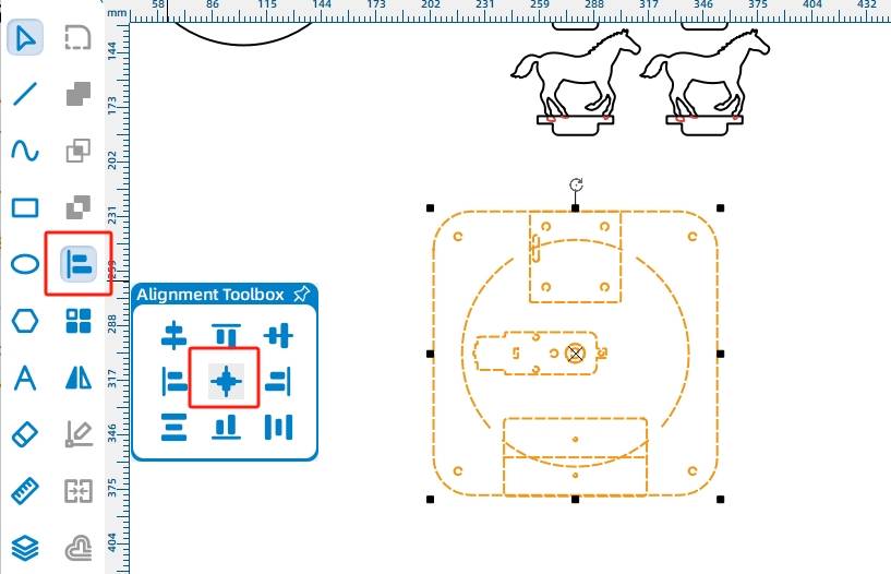
Group the slots into two columns so they can be rotated and aligned more easily. Rotate one slot group by 90 degrees, then center-align the horizontal and vertical slot groups.
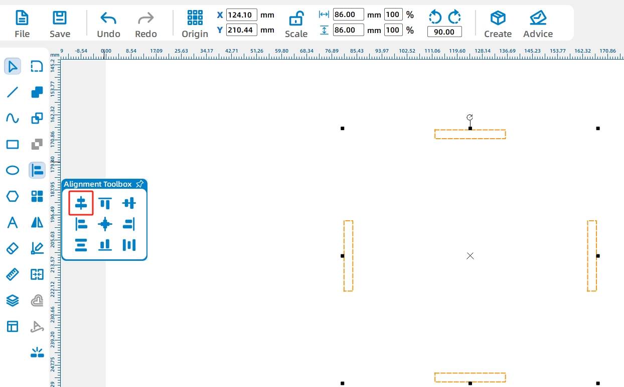
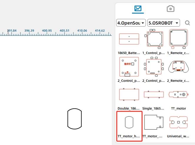
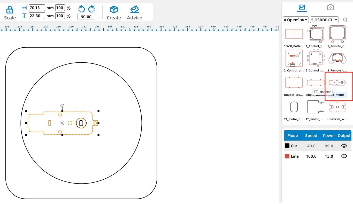
Add the TT motor hole by selecting the TT motor hole graphic from the Open Source Robotics Hardware section in the Gallery. Align the TT motor hole, the four slots, and the turntable circle to complete the turntable drawing.
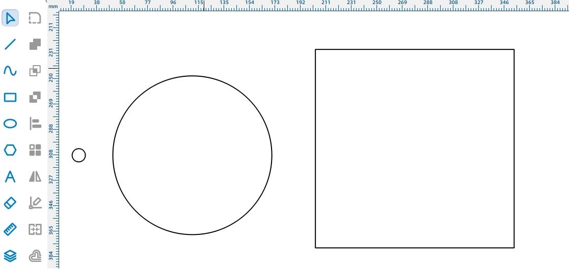
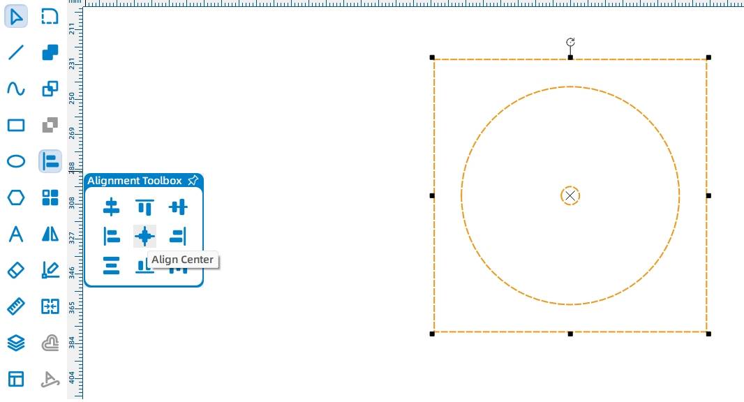
The base holds the motor, receiver, and battery. Start by drawing a 150 mm square base, a 120 mm reference circle, and a 10 mm center circle. Align the circles and square to the center.
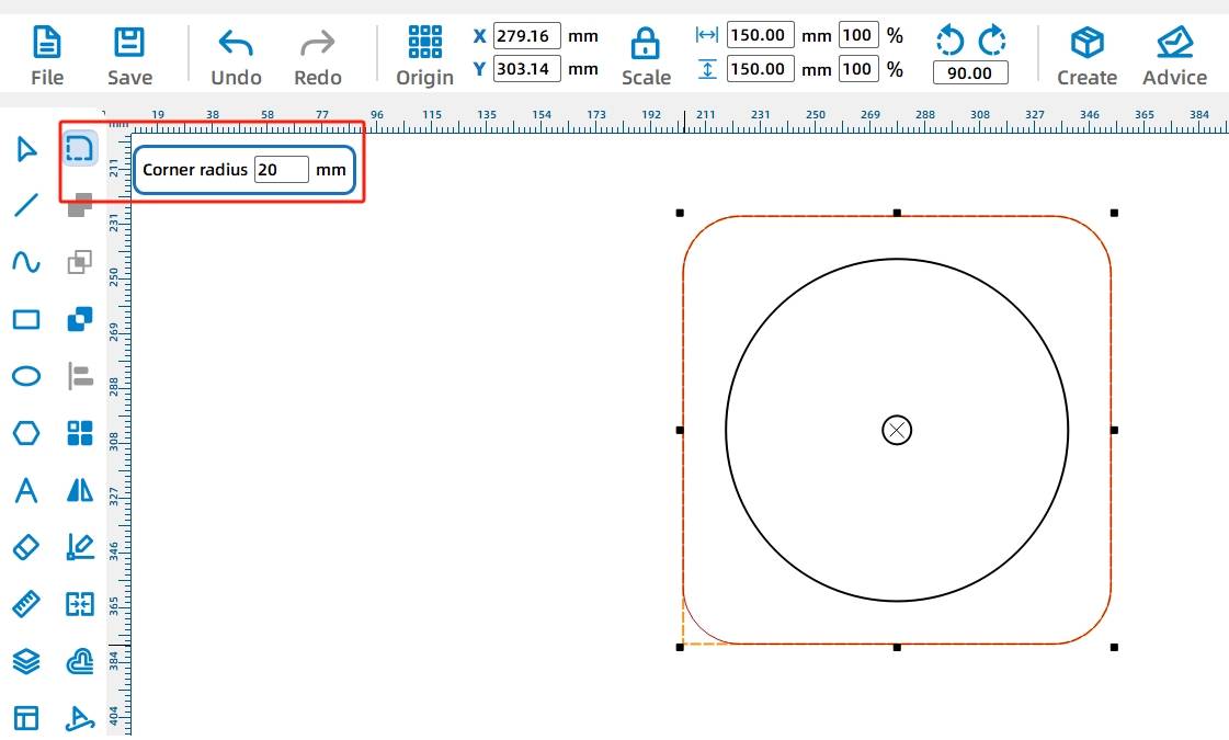
Use the Rounded Corner Tool with a 20 mm radius to round the four corners of the 150 mm square base.
From the Open Source Robotics section, add the OSROBOT motor graphic and group it. Align the motor’s circular hole with the center of the base, then remove any unnecessary reference circle.
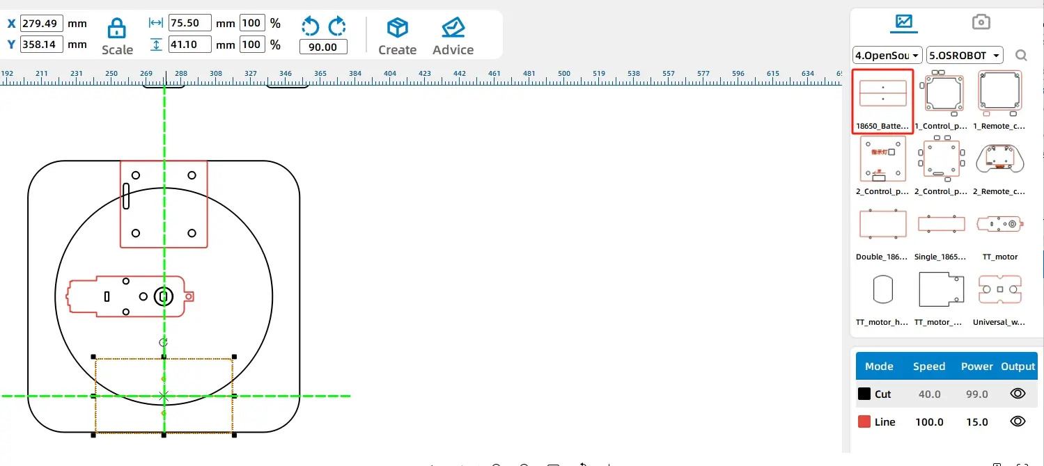
Add the control board and battery box graphics from the Open Source Robotics Hardware section. Rotate the control board graphic by -90 degrees, then place the receiver and battery box above and below the motor graphic.
Set the 120 mm reference circle to the red tracing layer. If some lines overlap at intersections, use the Eraser Tool to break and remove selected segments for a cleaner base drawing.
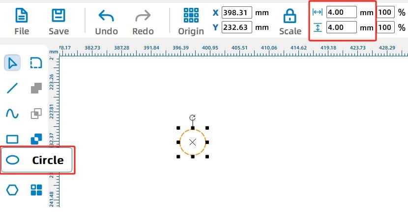
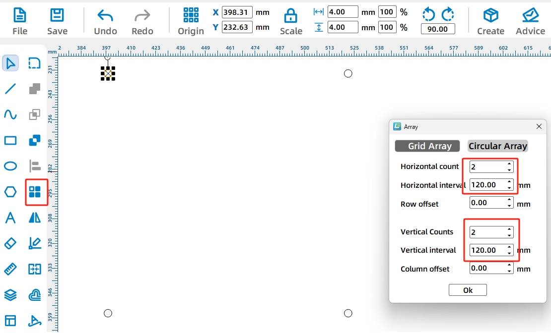
Group the base graphics. Then draw a 4 mm diameter circle for a screw hole and use Rectangular Array to create four holes with 120 mm horizontal and vertical spacing. Group the holes and center-align them with the base.
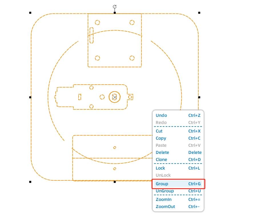
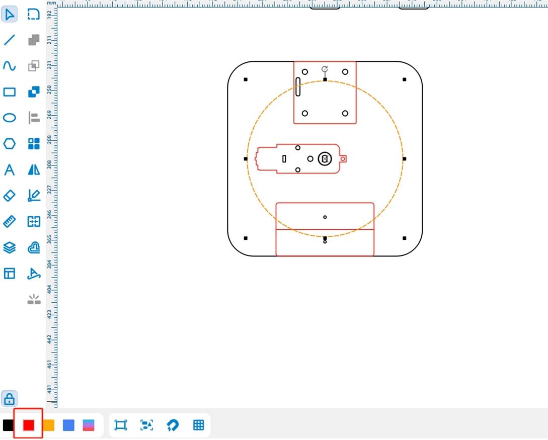
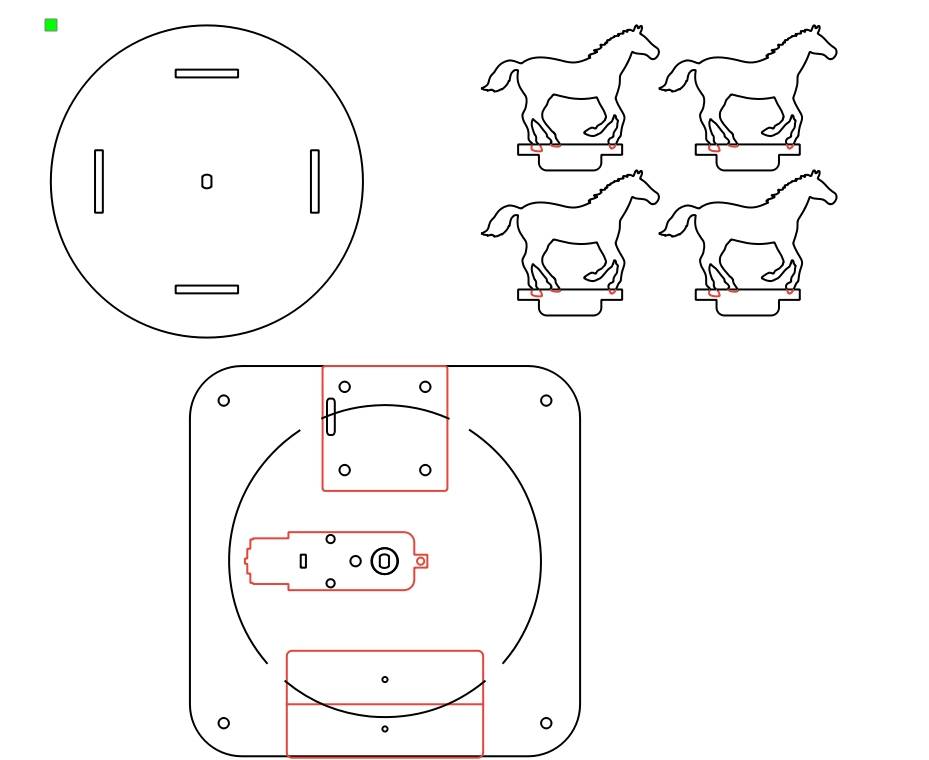
After the horse seats, turntable, and base are complete, review the final drawing layout before processing.
After finishing the drawing, set the laser processing parameters. The project uses tracing for red-layer details and cutting for black-layer outlines and holes.
Tracing: Double-click the red block in the processing area. Select basswood plywood as the material, choose tracing as the process, and set the processing thickness to 0.10.
Cutting: Double-click the black block in the processing area. Select basswood plywood as the material, choose cutting as the process, and set the processing thickness to 3.00.
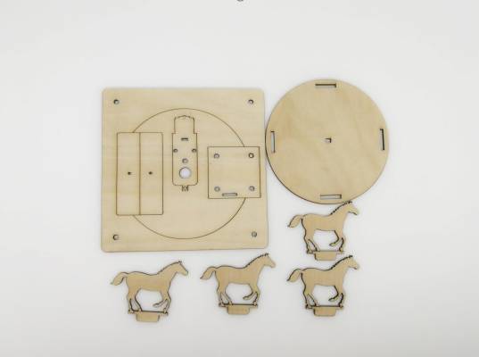
Turn on the laser cutting machine and laser switch. When the Start Fabrication button is ready, upload the drawing to the laser cutting machine and start cutting from the machine panel.
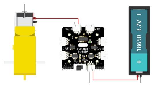
After the laser-cut parts are prepared, connect the circuit according to the wiring diagram. The motor, receiver, and battery work together to power the rotating carousel.
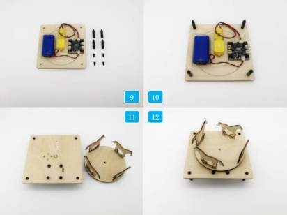
First, identify the four horse seats and the turntable. Insert the four horse seats into the slots on the turntable.
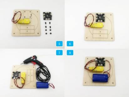
Next, prepare the base, TT motor, and M3 screws and nuts. Secure the TT motor to the base using the M3 hardware.
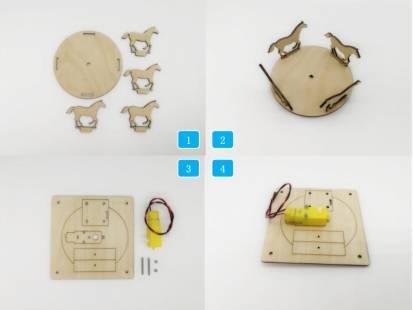
Install the receiver on the base using M4 screws and nuts. Add the 18650 battery, attach the battery to the base with a glue gun as described in the source workflow, and connect the motor, battery, and receiver according to the wiring diagram.
Install the M4 short screws and nylon posts on the back of the base. Finally, place the turntable with the installed horse seats onto the TT motor shaft.
Check whether the turntable rotates smoothly after being installed on the TT motor shaft.
Test whether the four horse seats fit securely in the turntable slots.
Confirm that the motor, receiver, battery, and wiring are fixed securely on the base.
Review whether the tracing details and cut outlines are clean after processing.
Improve the horse-seat design so the tenon connection blends more cleanly with the horse outline and reduces unnecessary line cleanup.
After laser cutting, wiring, and assembly, students complete a working carousel model that combines a rotating mechanical structure with remote-control components. The project demonstrates how digital drawings, material processing, electronics, and assembly come together in a powered maker project.
In this design, the horse-seat tenon intersects with the horse graphic, so students need to carefully erase and delete line segments. As an extension challenge, students can redesign the horse-seat connection so the tenon blends more naturally with the horse shape and reduces the risk of accidentally removing important details.
This project is suitable for classroom laser cutters that support cutting and tracing of sheet materials for small robotics and mechanism projects. For schools, makerspaces, and beginner STEAM labs, projects like motorized carousels, rotating platforms, remote-control structures, and laser-cut amusement-park models can be completed with a classroom laser cutter such as the Thunder Laser Bolt Series.
Teachers can choose the machine and material setup based on classroom space, project size, material thickness, electronic components, and learning goals. The same LaserMaker workflow can also be adapted for other CO2 laser machines when students move on to larger moving models or more advanced robotics projects.
Talk To Our Experts Now!
Please leave your contact information so that we can serve you better.
NEED HELP FINDING THE RIGHT SOLUTION?
Talk to our team for machine recommendations, application advice, and support based on your needs.

 Stable & Consistent MachinesUnlimited ApplicationRobust After-sales SupportFactory Direct Supply


