Drawing Tools
Select Tool
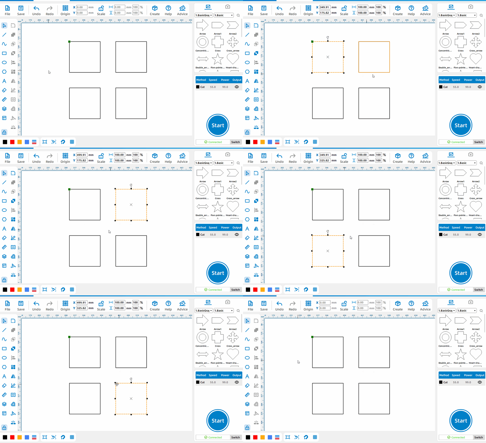
Select a single pattern
Move the cursor to the edge of the pattern and left-click to select a single pattern.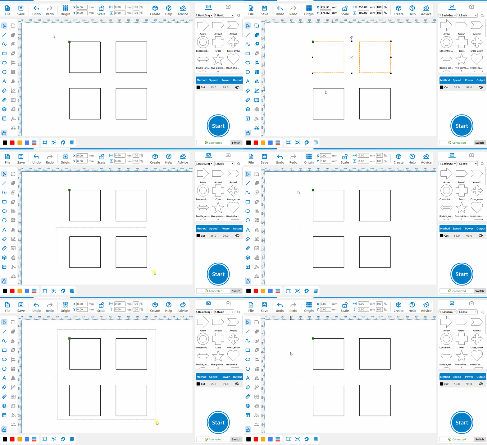
Frame multiple patterns
Left-click and drag to select all patterns in the dragged area.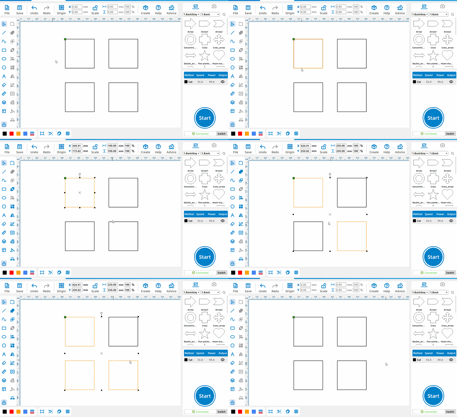
Select multiple patterns
After selecting a single pattern, Press Ctrl and select other patterns to select multiple patterns at the same time.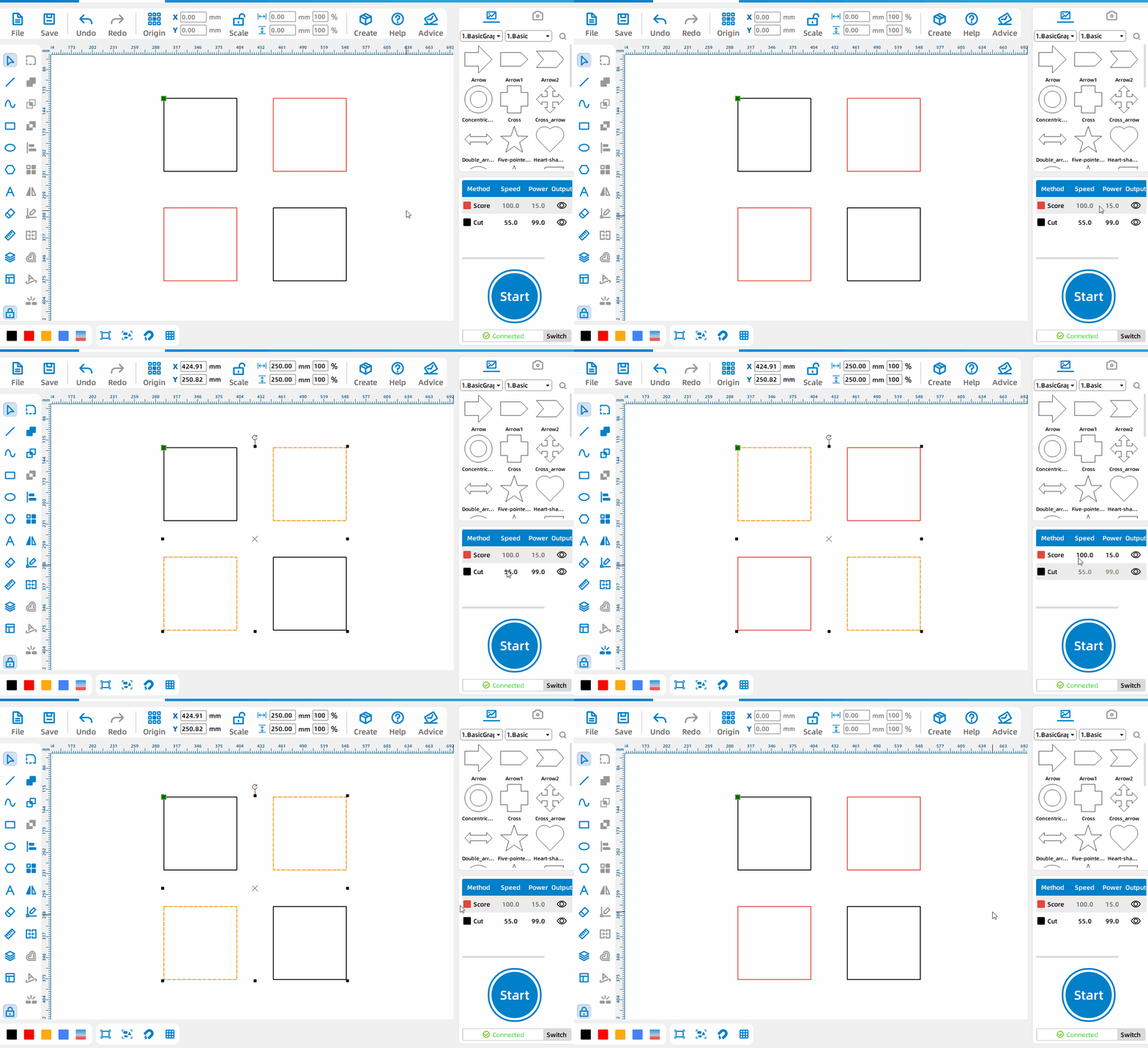
Select patterns by layer
Right-click the corresponding layer to select all patterns under this layer.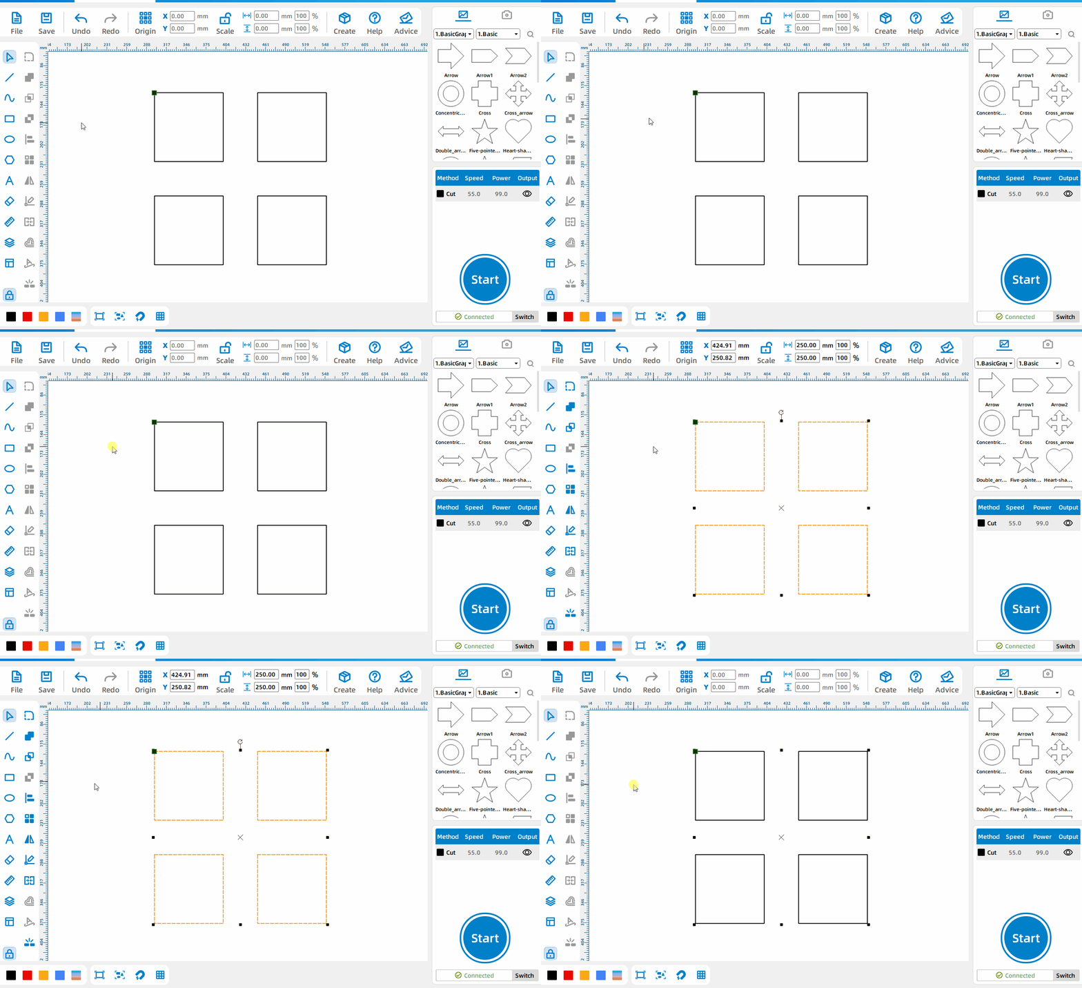
Select all patterns on canvas
Press Ctrl+A on the keyboard to select all patterns.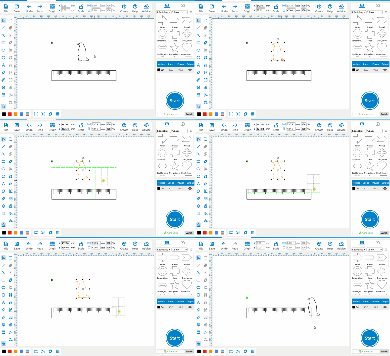
Drag pattern
Press the left mouse button over the selected pattern and drag to move pattern.
Line Tool
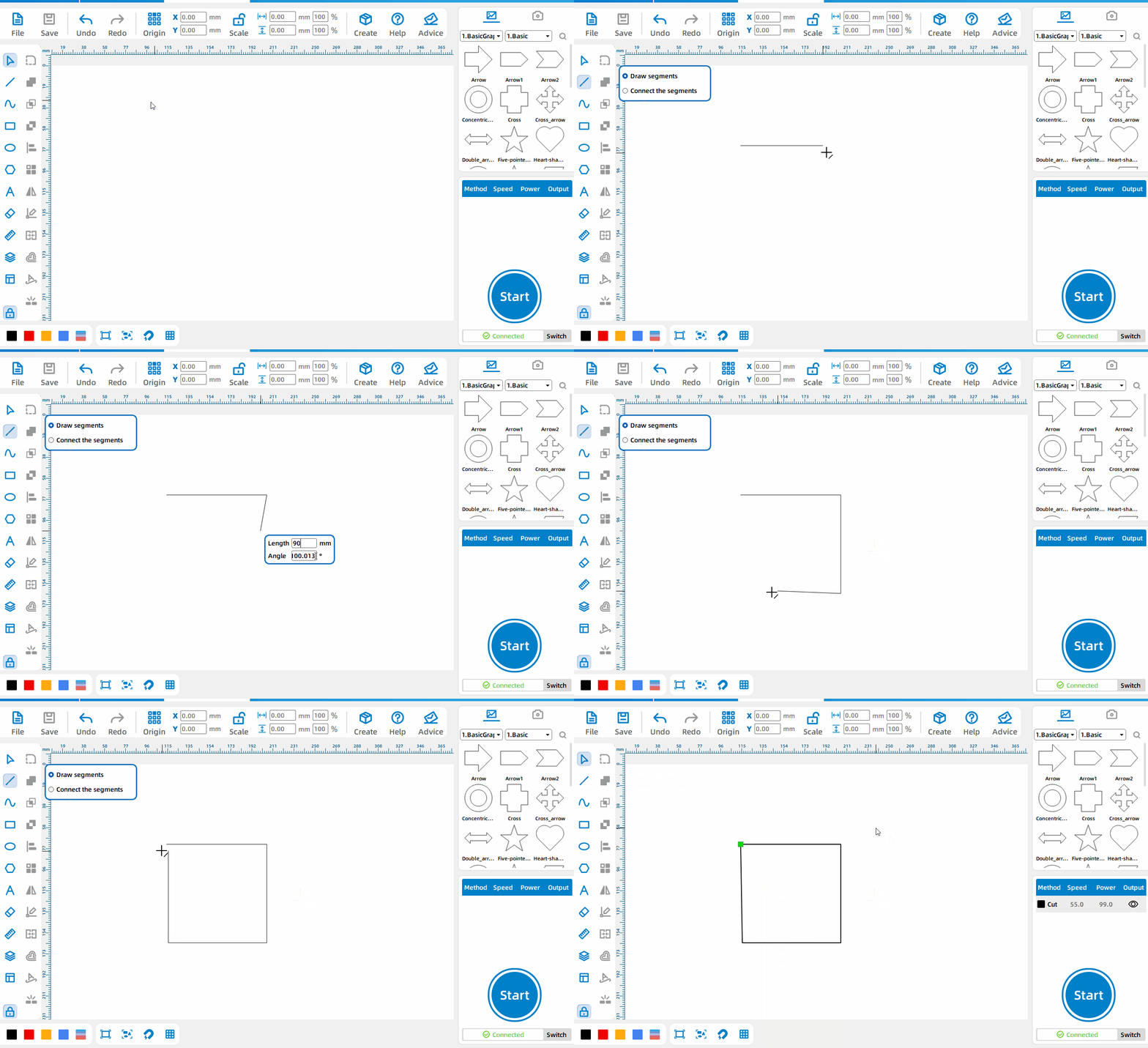
[CTRL] Draws the line and [TAB] draws the Angle and length
Can draw any line, Press the left mouse button to start drawing, Press the right mouse button end drawing; Press Ctrl to draw horizontal or vertical lines. Press Tab to draw a line segment of the specified length and Angle at the fold point.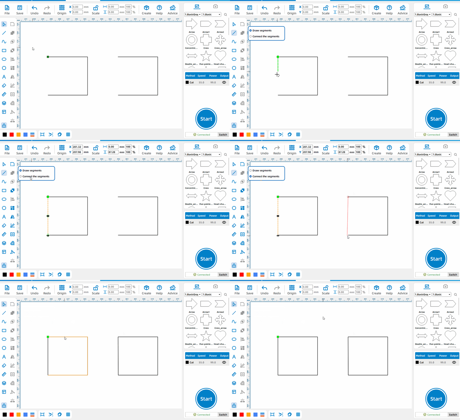
The difference between drawing line segments and connecting line segments
The line segment tool is divided into [Draw Line Segment] and [Connect Line Segment]. [Draw Line Segment] is used to draw various lines. Each drawing is an independent primitive; [Connect Line Segment] is used to connect line segments with openings in the primitive. The connected line segment and the original graphic element are a whole.
Curve Tool
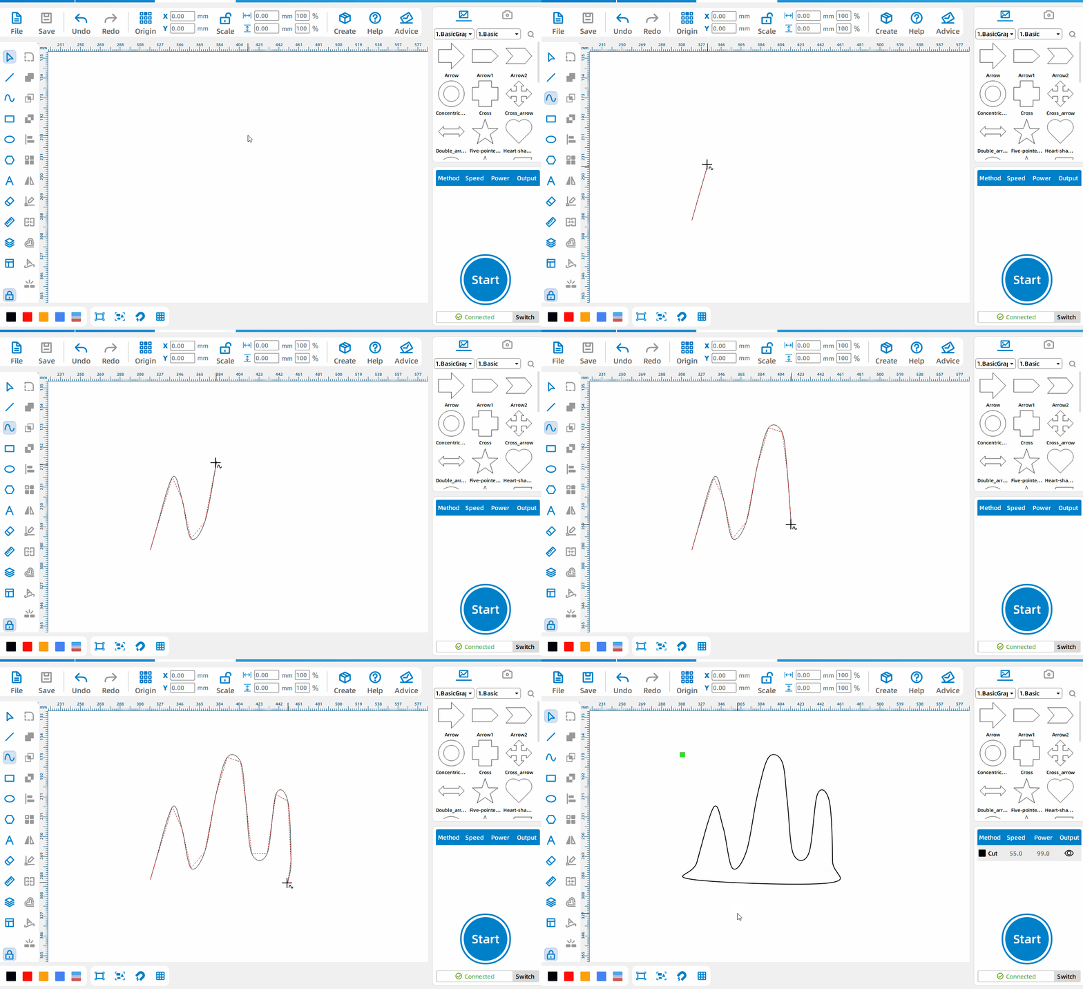
Draw a curve
Left-click to start drawing curves and control points, and right-click to end the drawing.
Rectangle Tool
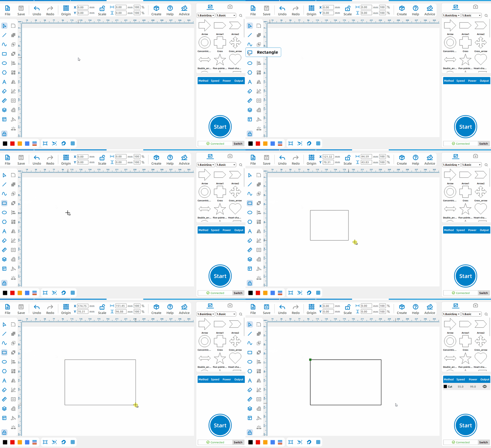
Draw a rectangle
Left-click and drag to draw a rectangle, and release the left mouse button to end drawing.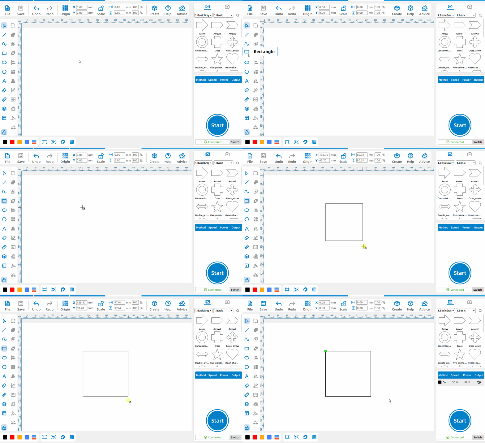
Draw a square
Press Ctrl when drawing a rectangle to draw a square.
Circle Tool
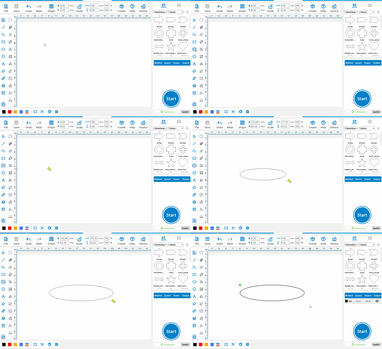
Draw an ellipse
Left-click and drag to draw an ellipse, and release the left mouse button to end drawing.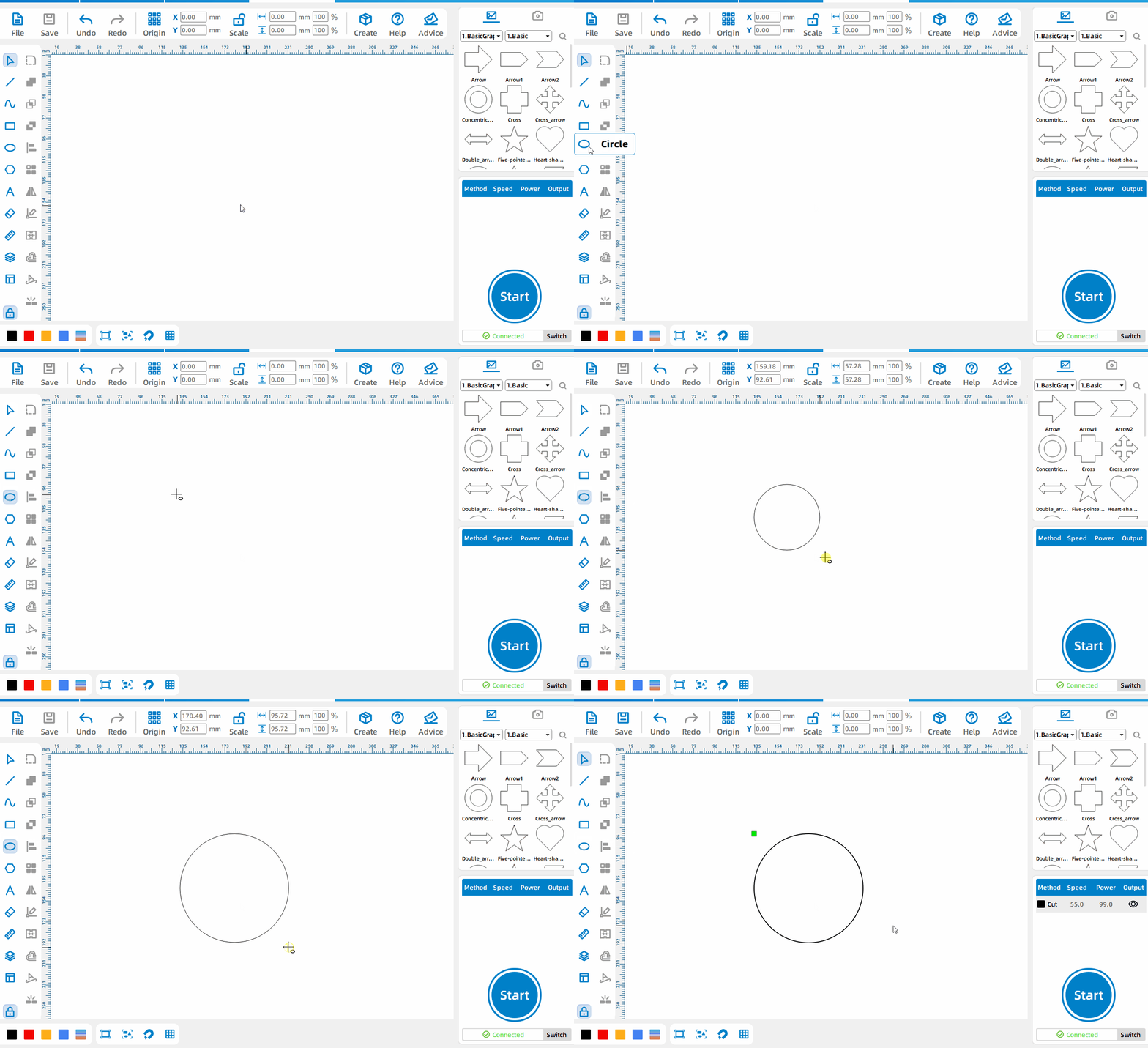
Draw a circle
Press Ctrl when drawing an ellipse to draw a perfect circle.
Polygon Tool
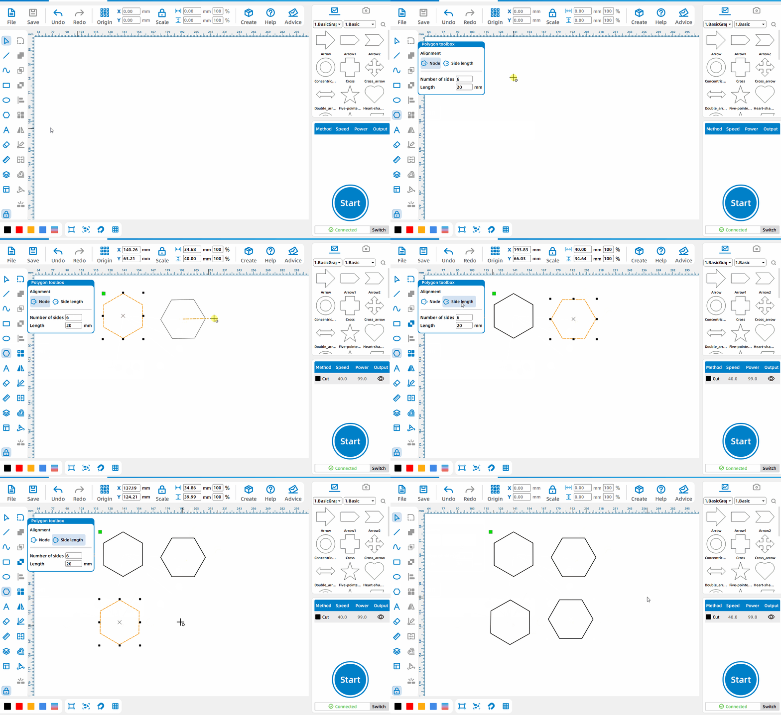
Draw Polygon
Two alignment methods can be selected, set the side length and the number of sides.For polygons drawn in [Node] mode, a certain node of the primitive will be aligned with the mouse and rotate with the mouse; for polygons drawn in [Side Length] mode, a certain node of the primitive will be aligned with the mouse. Align the midpoint of one side with the mouse and follow the mouse rotation; press Ctrl, the drawn polygon will be in a horizontal or vertical position, and rotate 90 degrees.
Text Tool
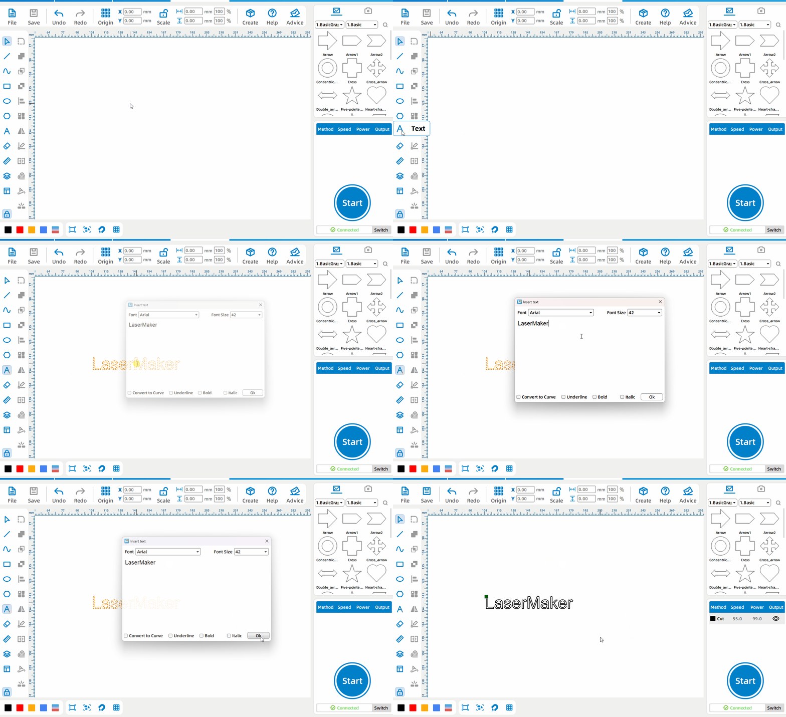
Generated text
Left-click where you want to generate text to generate text.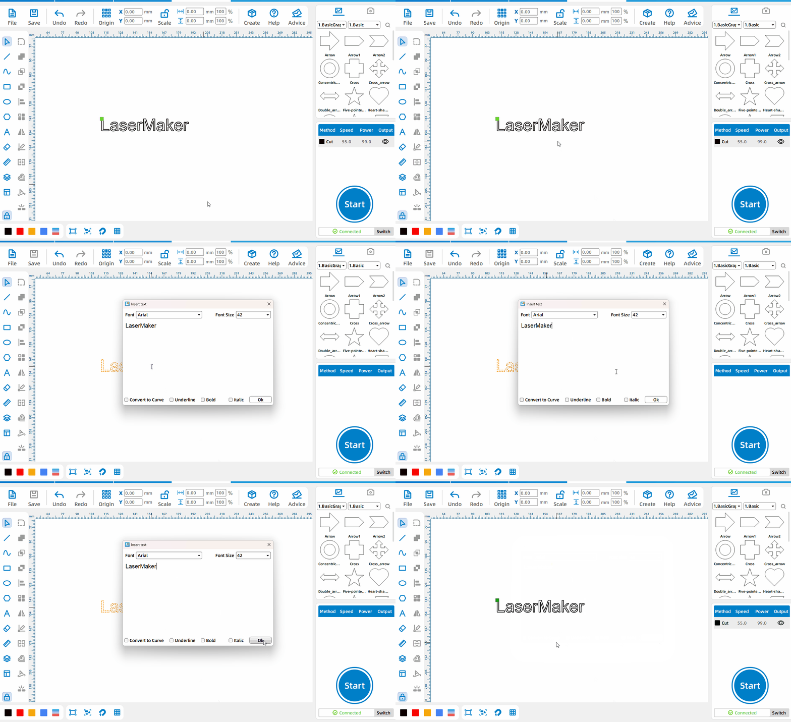
Edit text
Double-click the generated text and left-click to re-enter the text editing mode.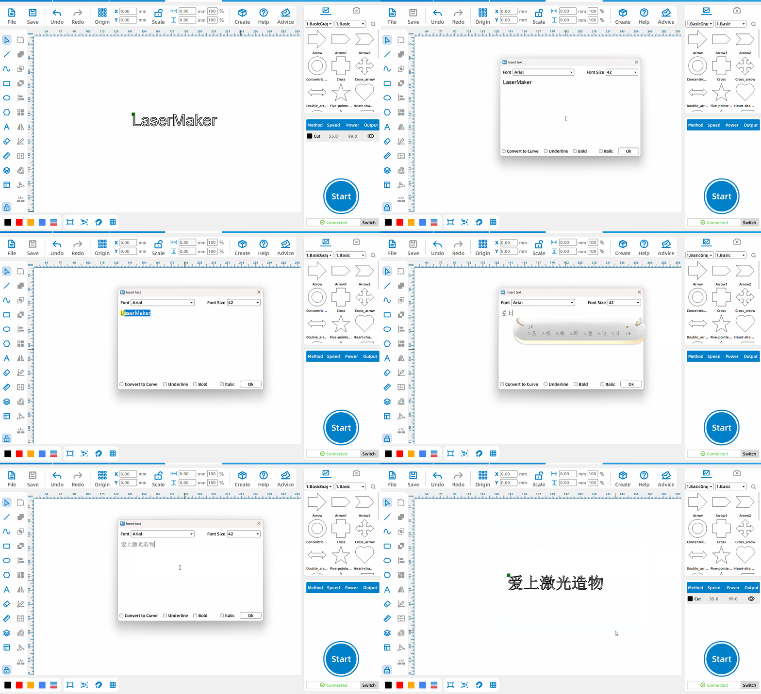
Change content
Change the text box in the text editing window to change the generated text content.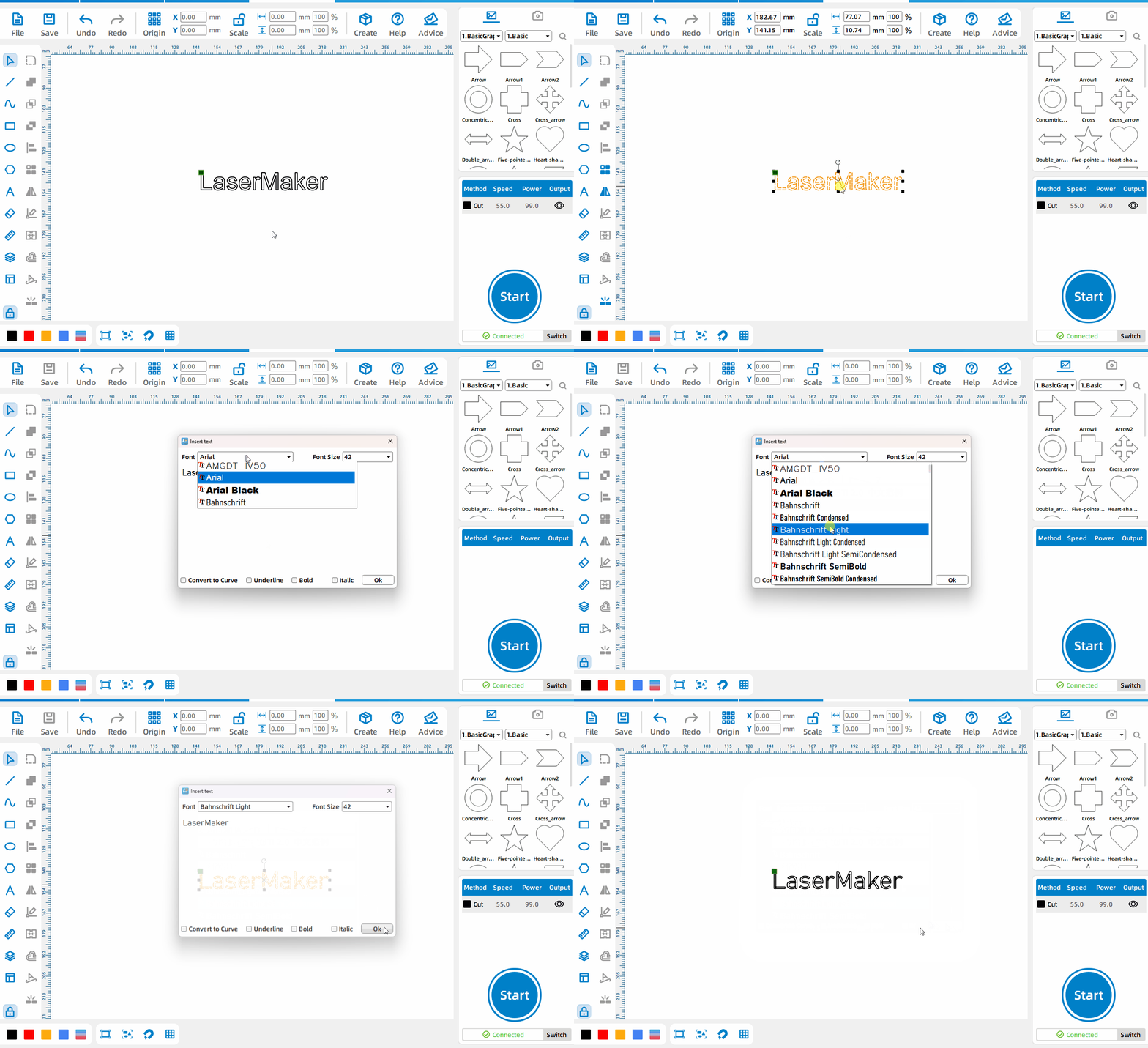
Change font
Left-click on the drop-down bar to the right of the text to bring up the font list and change the font.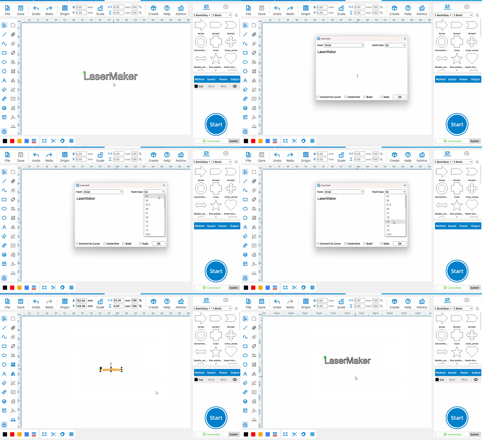
Change font size
In addition to directly setting the length and width of the font, you can also directly set the specific font size.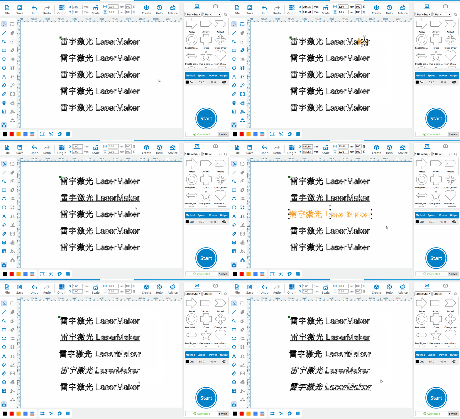
Set text to underline, bold, tilt, or curve the text
When drawing or editing text, you can underline, bold, tilt, or turn the text into a curve.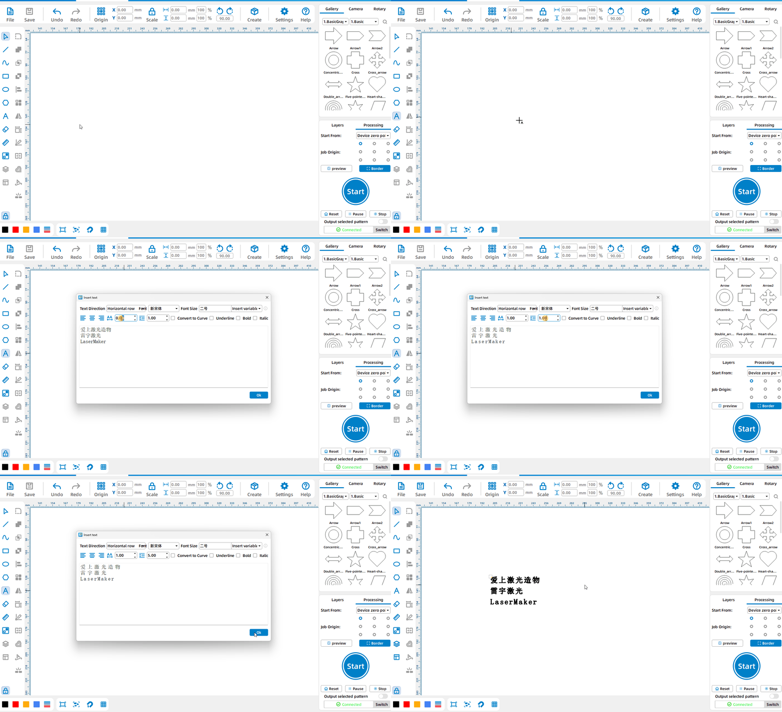
Word spacing and line spacing
Left-click the [Text Tool], enter the text, you can adjust the word spacing and line spacing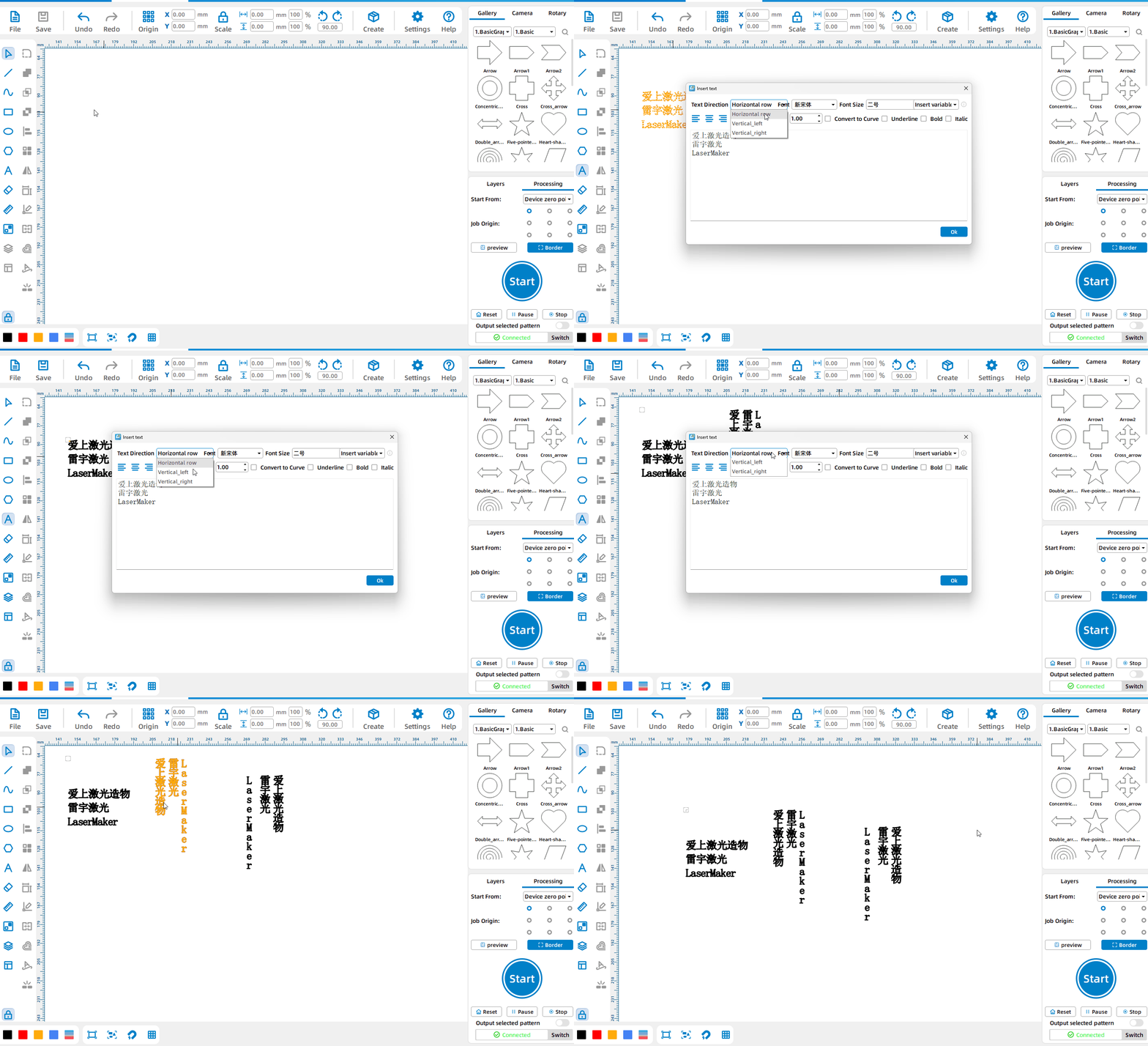
Set text direction.
Left-click the [Text Tool], enter the text, and set the text direction to achieve different effects such as horizontal text or vertical text.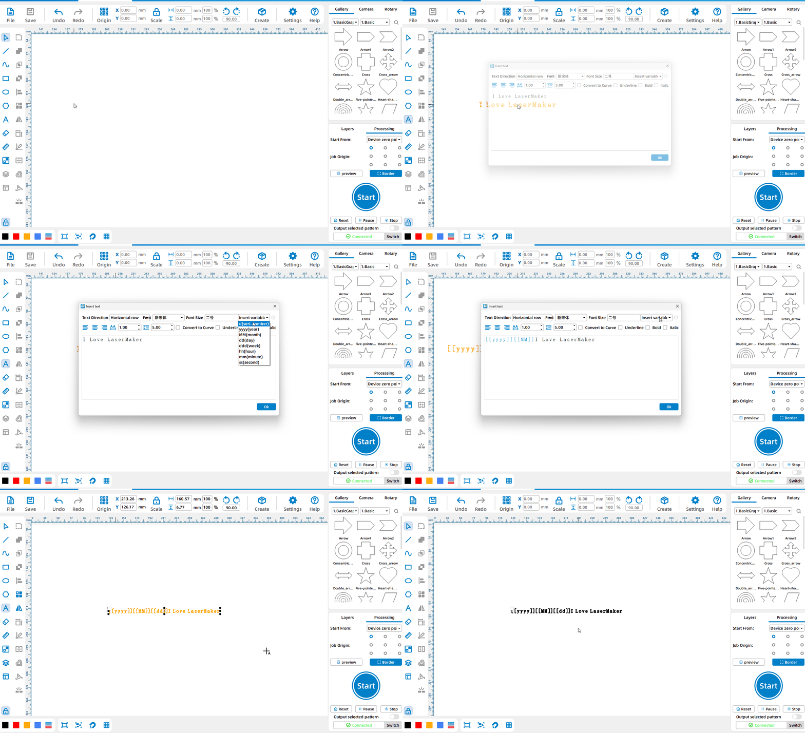
Insert variable text
Left-click the [Text Tool], click [Insert Text], select the required variable, generate text on the canvas, and hover the mouse over the text to display the specific content of the variable text.
Measuring Tool
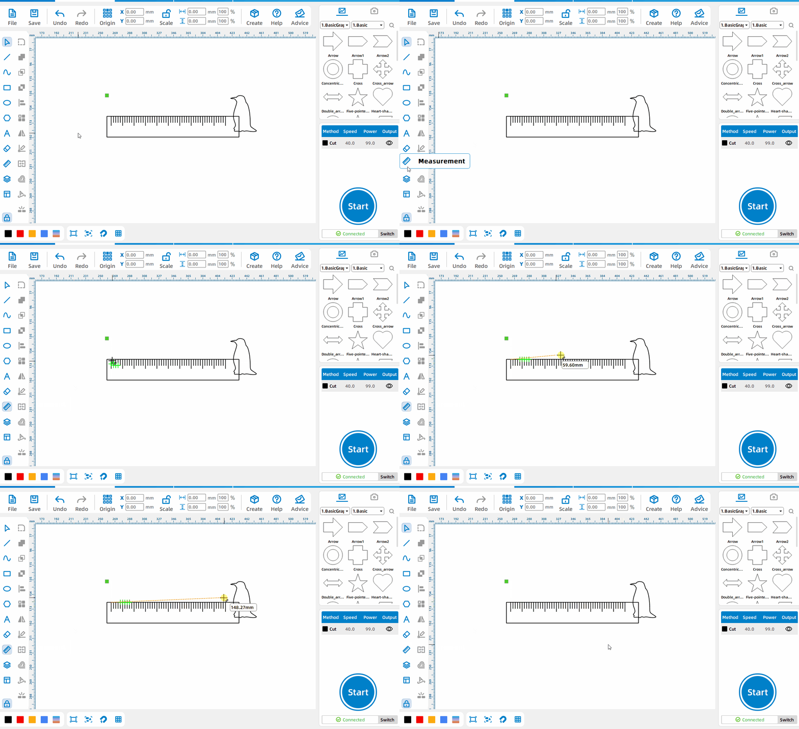
Measure the distance between two points
Press and hold the left mouse button at the starting point of measurement and drag the mouse to measure the distance between two points.
Rounded Corners Tool
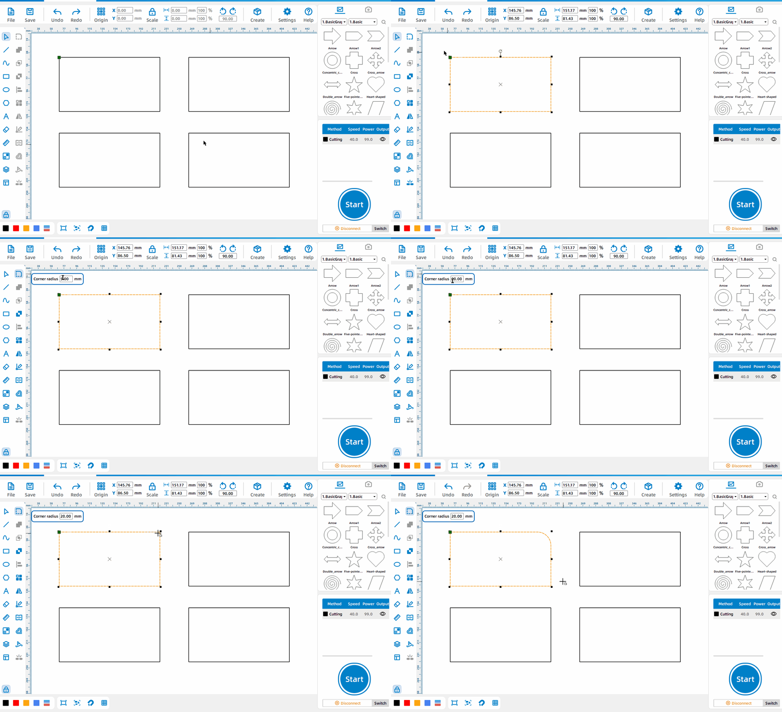
Draw rounded corners
Select the pattern, left-click the [Round Corner Tool] , set the rounded corner size, and click the corner that needs to be rounded.
Use of the Gallery
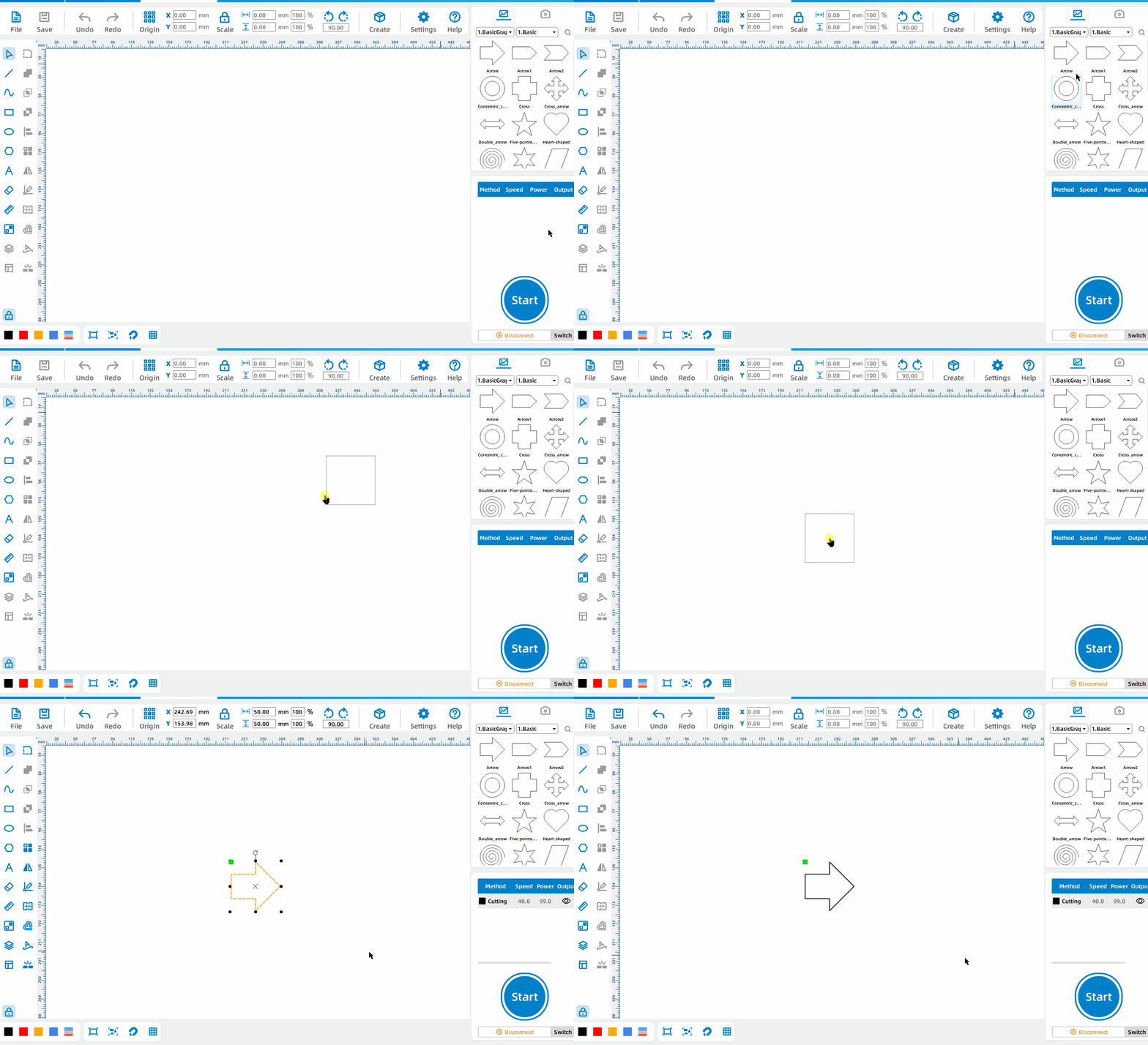
Directly use drawings from the gallery
Select the drawing, press and hold the left mouse button, and drag the drawing onto the canvas.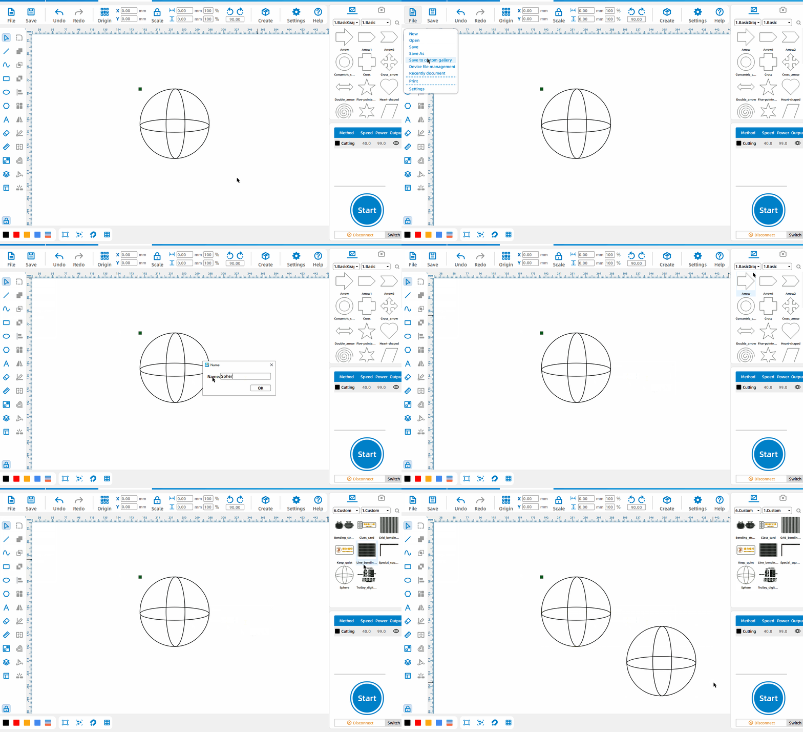
Save To Custom Gallery
Click [File] – [Save to Custom Gallery] and set the drawing name; you can find the saved drawings in [Gallery] – [6. Custom].
Code Generation
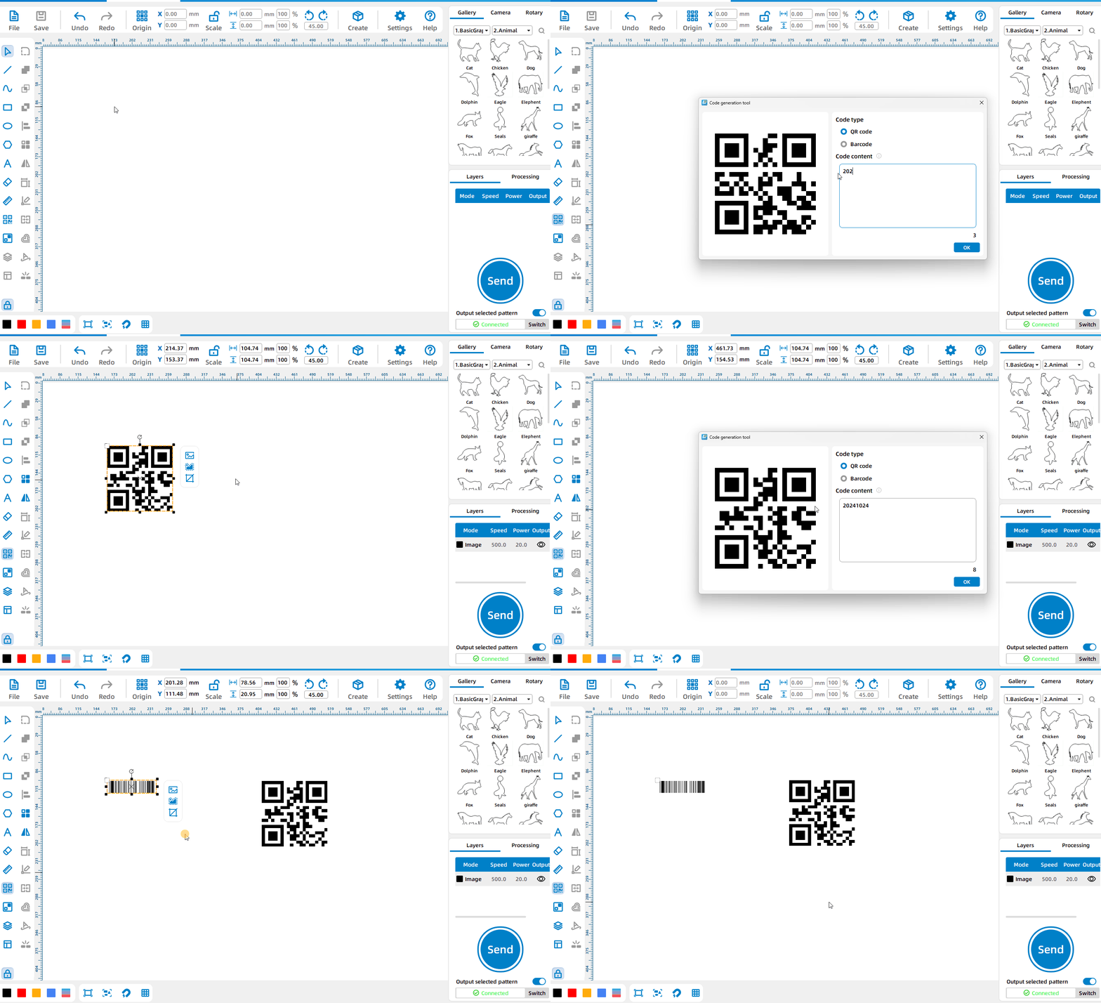
Generate QR code or barcode
Left-click the [Code Generation Tool], select [Code Type], enter the text, and click [OK] to generate a QR code or barcode.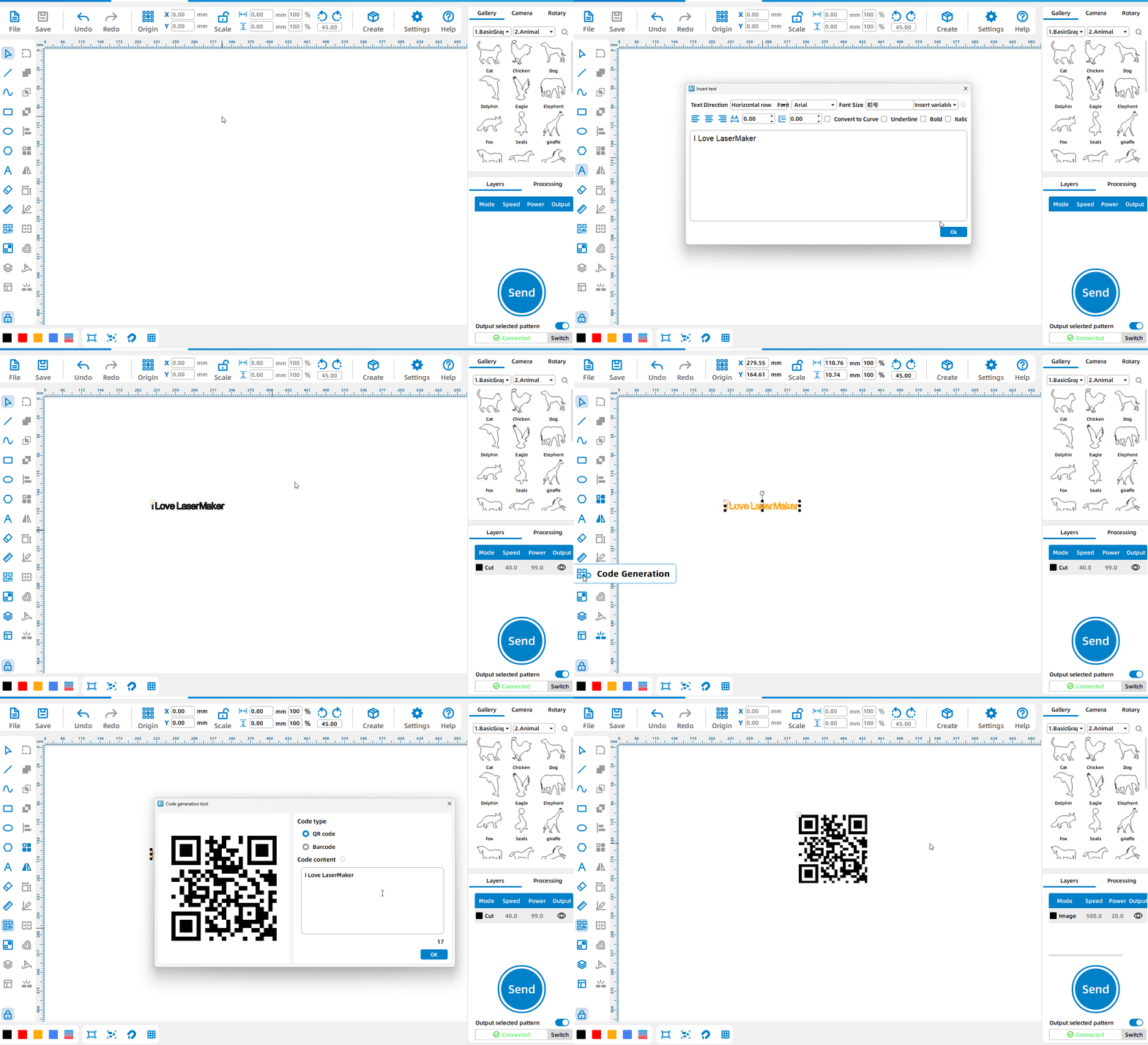
Convert existing text into barcode
Select the text on the canvas, left-click the [Code Generation Tool], select [Code Type], and click [OK] to convert the text on the canvas into a code.
Boolean Tools
Union Tool
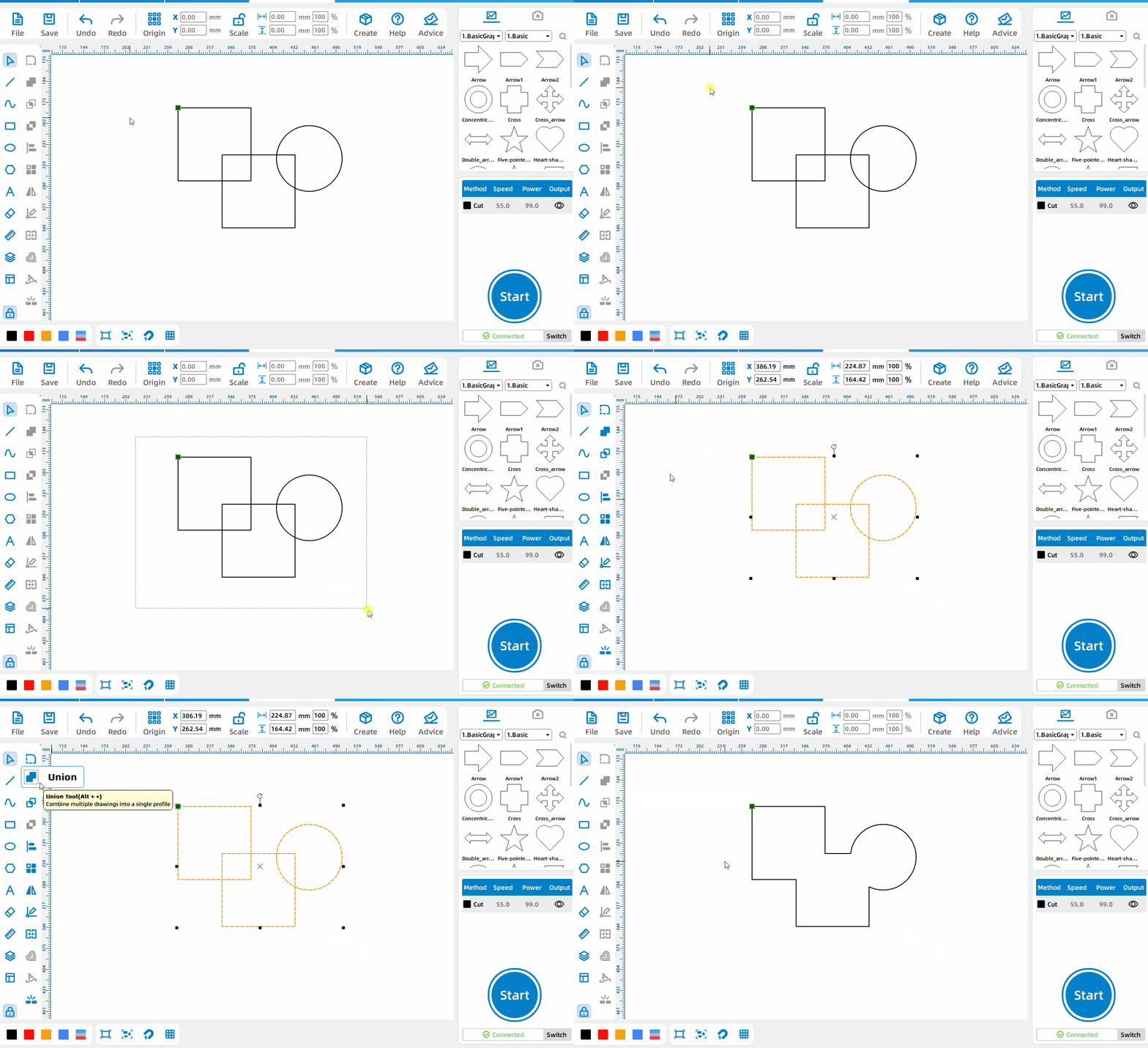
Union Operation
Frame two or more patterns, then click the Union button.
Intersection Tool
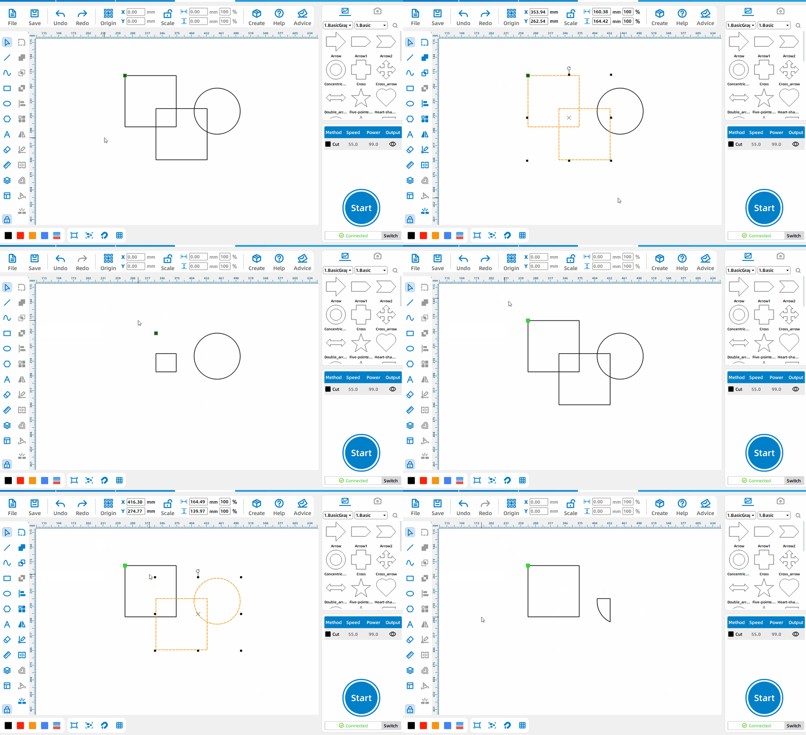
Intersection Operation
Frame two or more patterns, then click the Intersection button.
Difference Set Tool
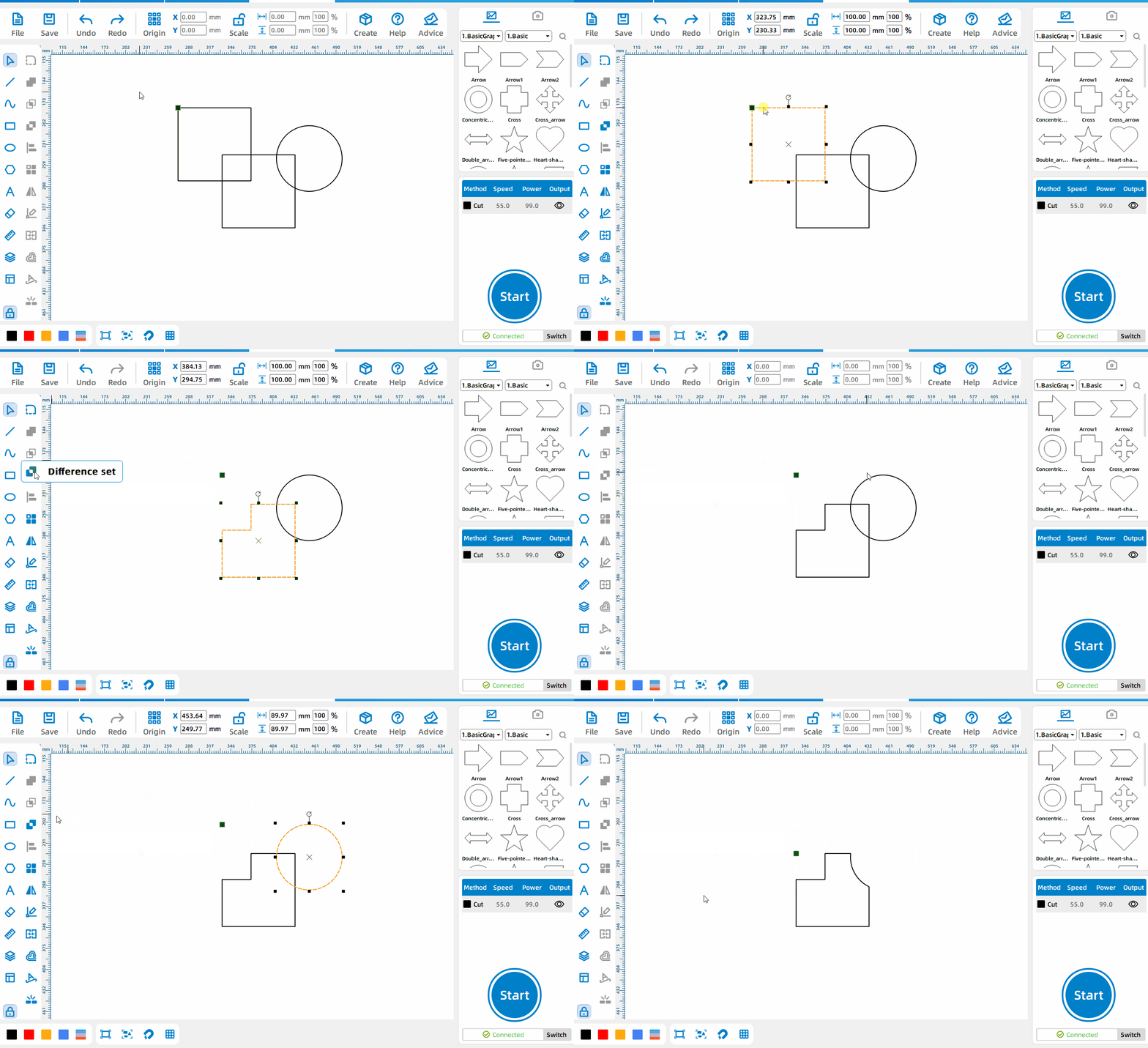
Difference Set Operation
Frame a pattern,then click the difference button.
Adjustment Tools
Eraser Tool
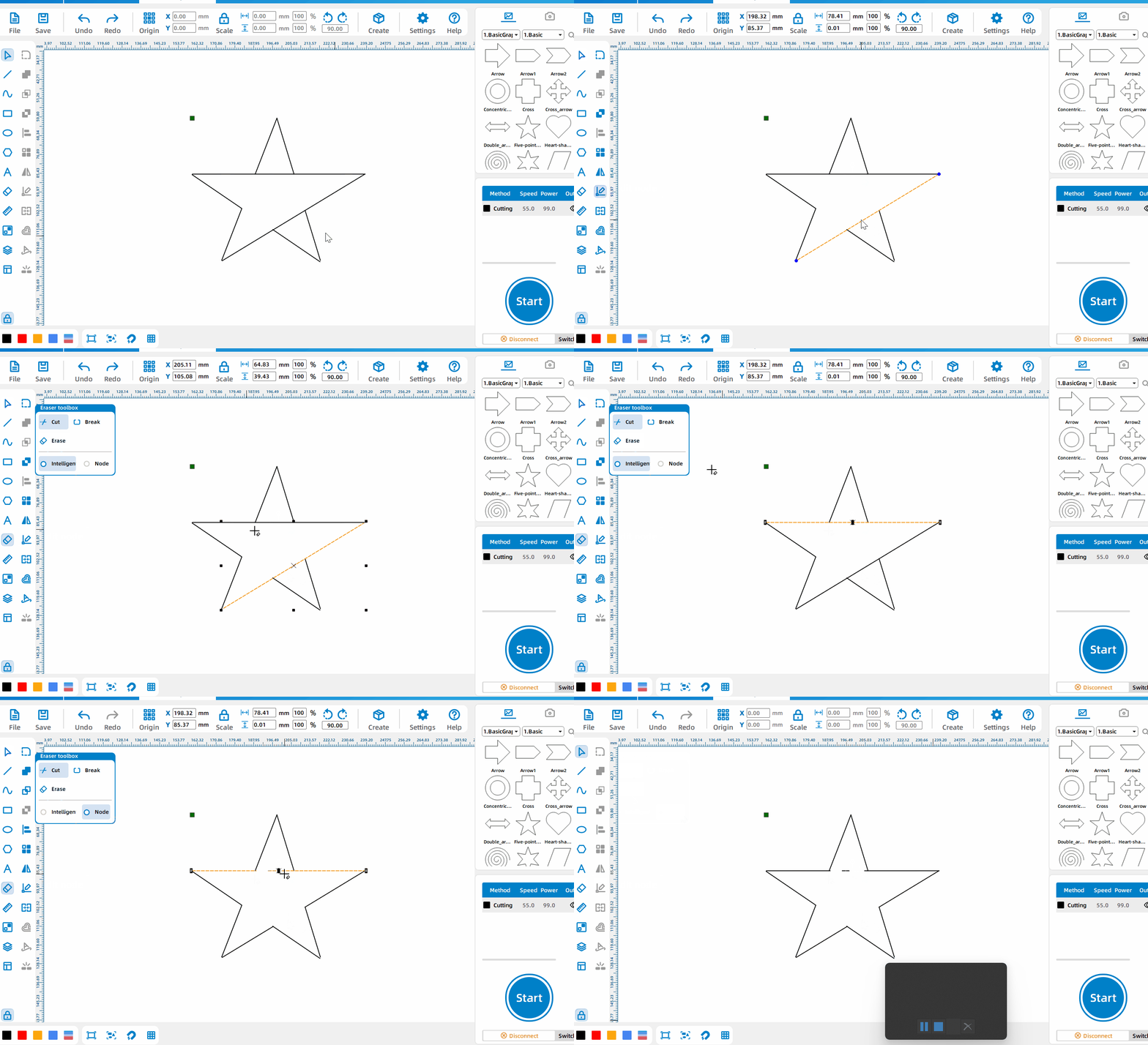
Cut the line segments
Select the [Crop] mode and left-click on the line segment that needs to be cut; when selecting [Intelligent], line segments with many nodes will be cut by intersection points, line segments with few nodes will be cut by nodes, and when [Node] is selected, all line segments will be cut. Crop by node of line segment.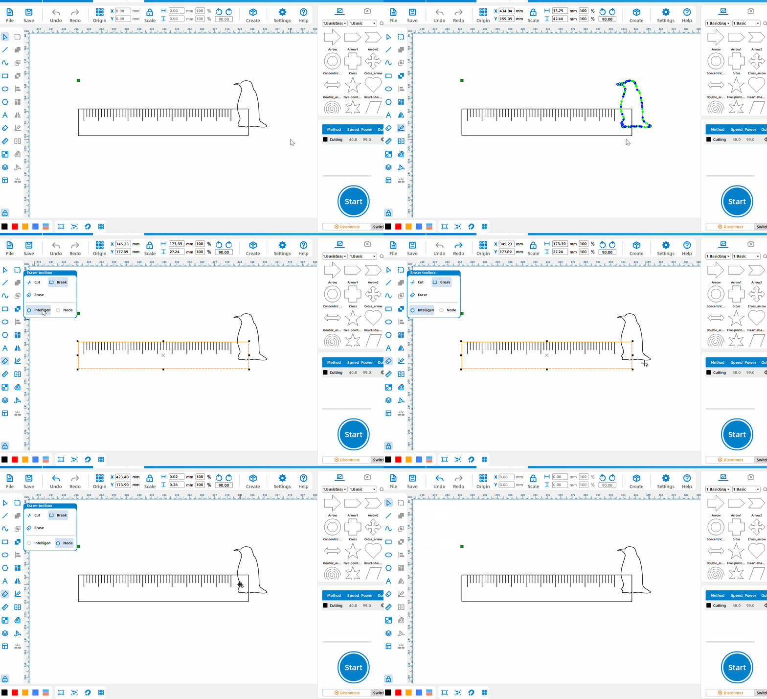
Break line segment
Select the [Interrupt] mode, left-click on the line segment that needs to be interrupted, and then delete the interrupted rectangular line. The internal lines of the penguin will be turned into a red layer; when [Smart] is selected, there are many nodes. The line segments are broken according to the intersection point, and the line segments with few nodes are broken according to the nodes. Select [Node] to break all the line segments according to the nodes of the line segments.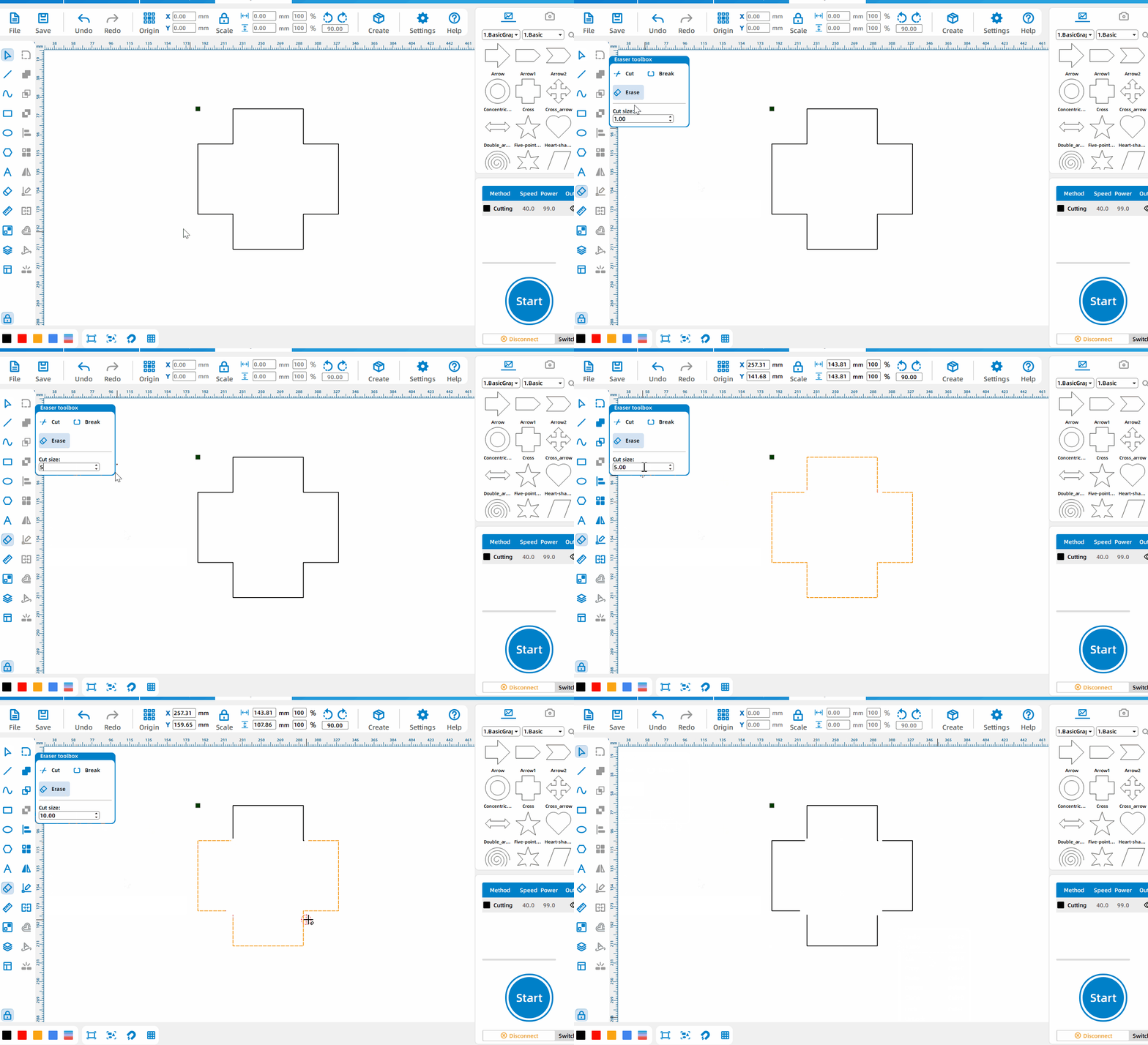
Eraser
Select the [Eraser] mode, set the erasure diameter and left-click where the erasure is needed.
Alignment Tool
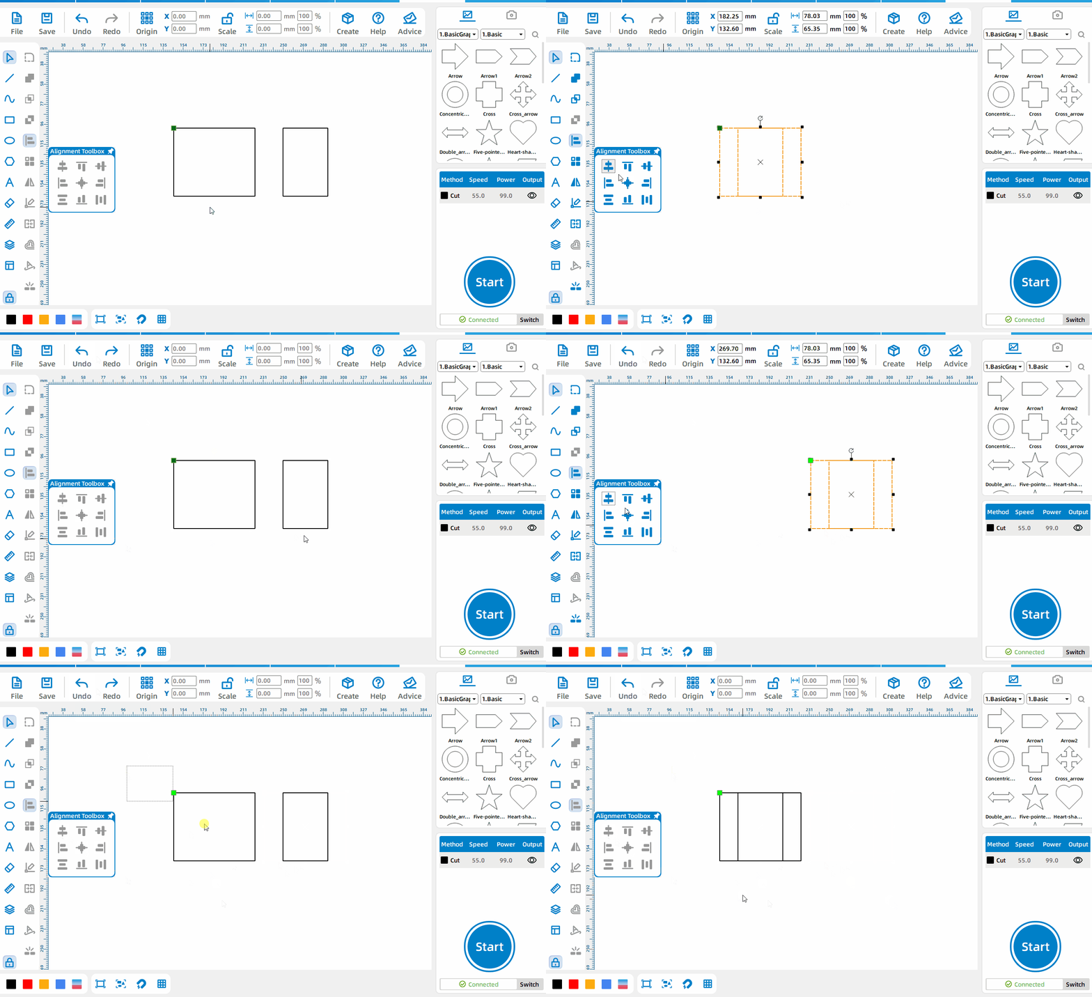
Alignment reference
If you press Ctrl to select the primitives one by one, the last selected primitive will be used as the alignment reference; if all primitives are selected, the largest primitive will be used as the alignment reference.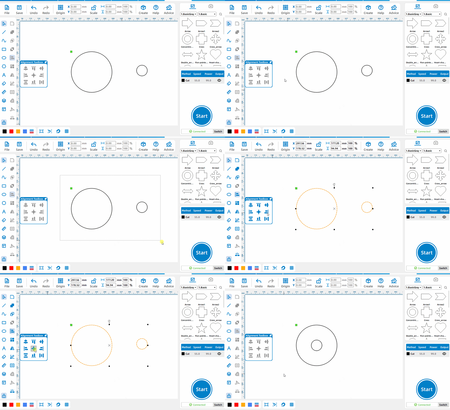
Center aligned
Press the left mouse button to select all primitives and click Center Align to align all primitives with the center point.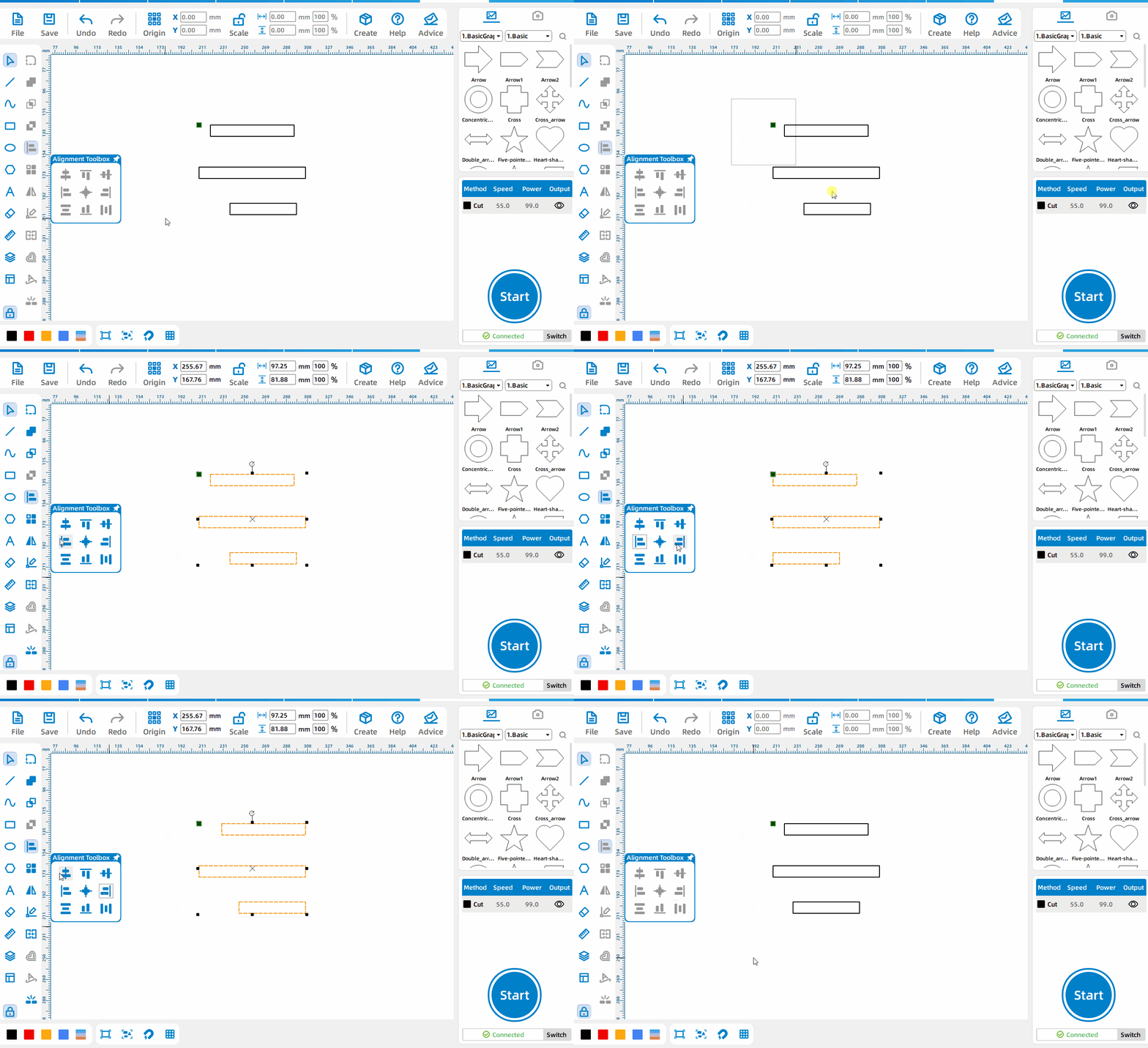
Left alignment, right alignment, horizontal alignment
Press the left mouse button to select all primitives, and click Align Horizontally to align all primitives with the same horizontal point.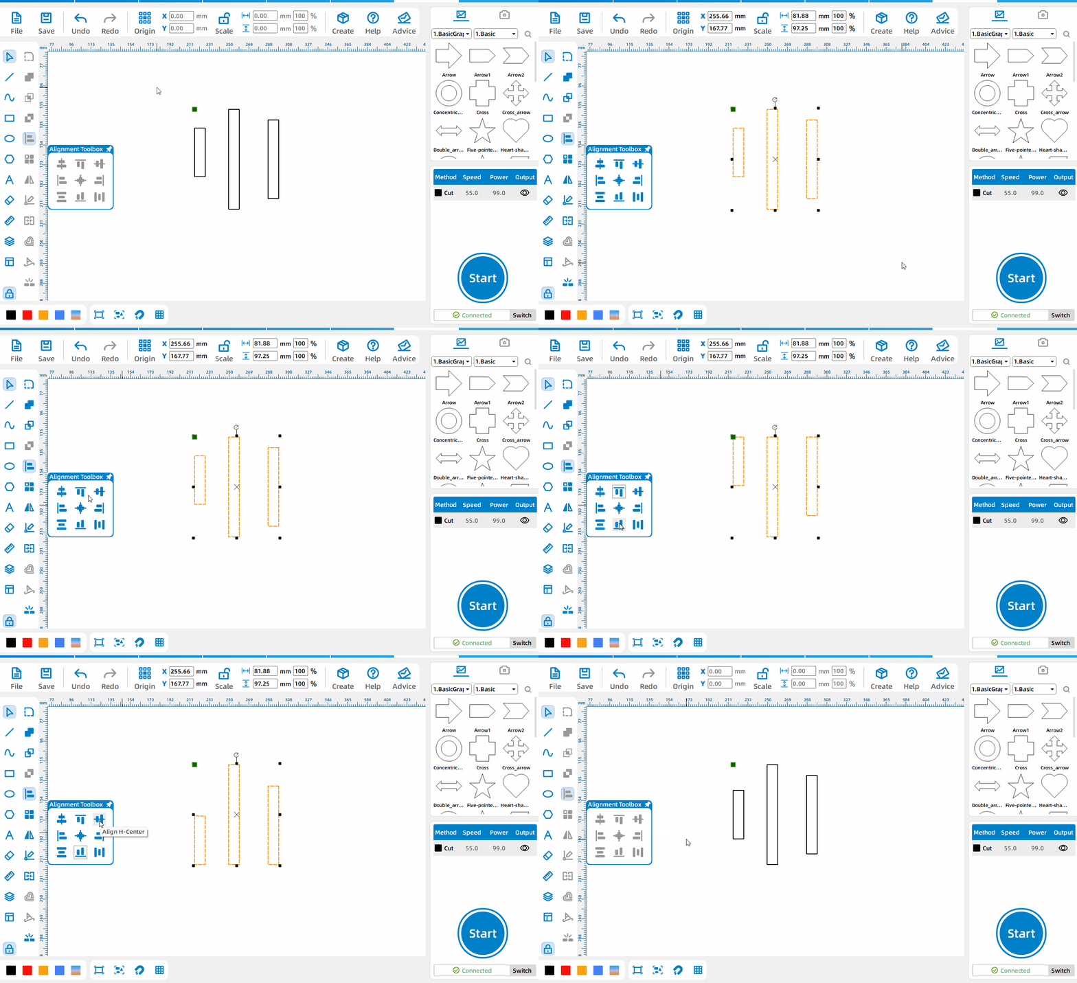
Top alignment, bottom alignment, vertical alignment
Press the left mouse button, select all primitives, and click Vertical Align to align all primitives with the same vertical point.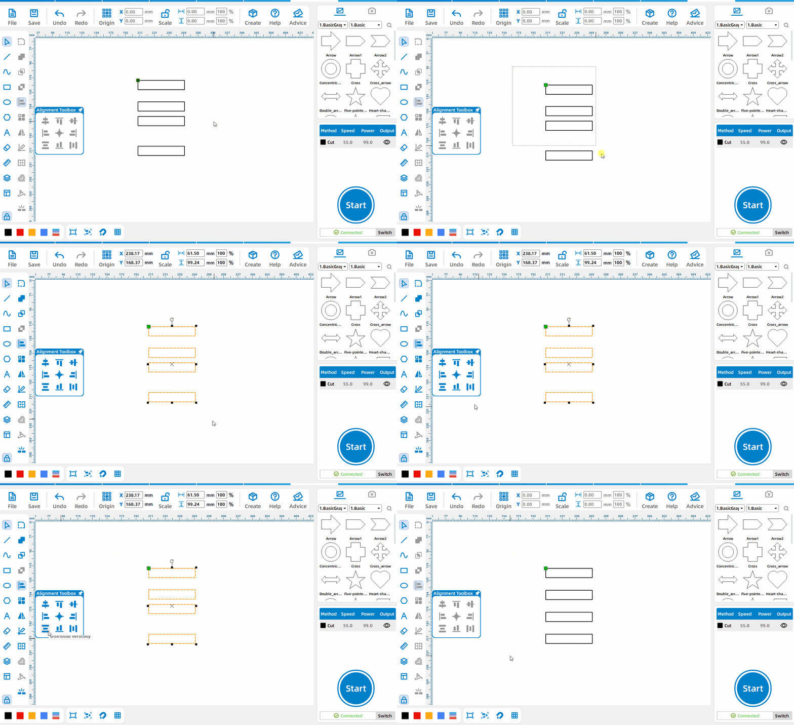
Evenly distributed vertically
Press the left mouse button, select all graphics elements, and click Vertical Distribution to adjust the vertical spacing of all graphics elements to be consistent.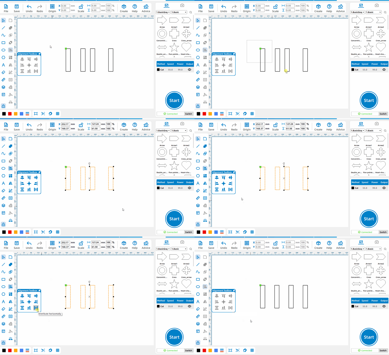
Evenly distributed horizontally
Press the left mouse button, select all the graphics elements, and click Horizontal Even Distribution to adjust the horizontal spacing of all graphics elements to be consistent.
Array Tool
Grid Array
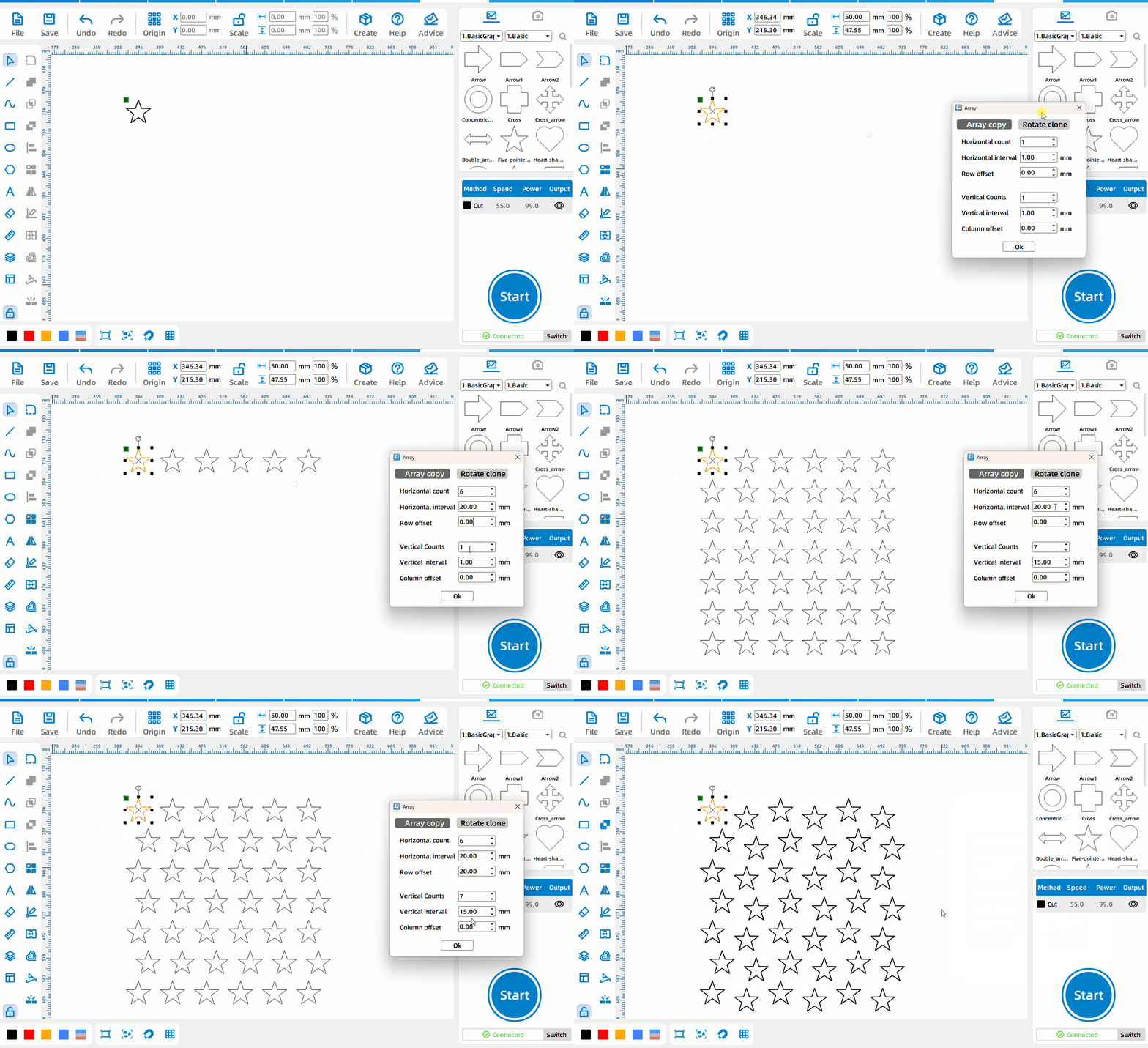
Select [Rectangular Array] mode and set parameters, where [Horizontal Number] is the total number of horizontal elements behind the array, [Horizontal Spacing] is the spacing between two primitives, and it is the rightmost side of the left primitive and the right picture The distance to the far left of the element, [Offset of alternate rows] is the offset distance between the first row and the starting position of the first row in the horizontal direction, and there will be an offset in every other row; [Number of verticals] is the vertical direction after the array The total number of pixels, [vertical spacing] is the spacing between two primitives, is the distance between the bottom of the previous primitive and the top of the next primitive, [column offset] is the first column and the second column The offset distance of the starting position in the vertical direction, there will be an offset in every other column.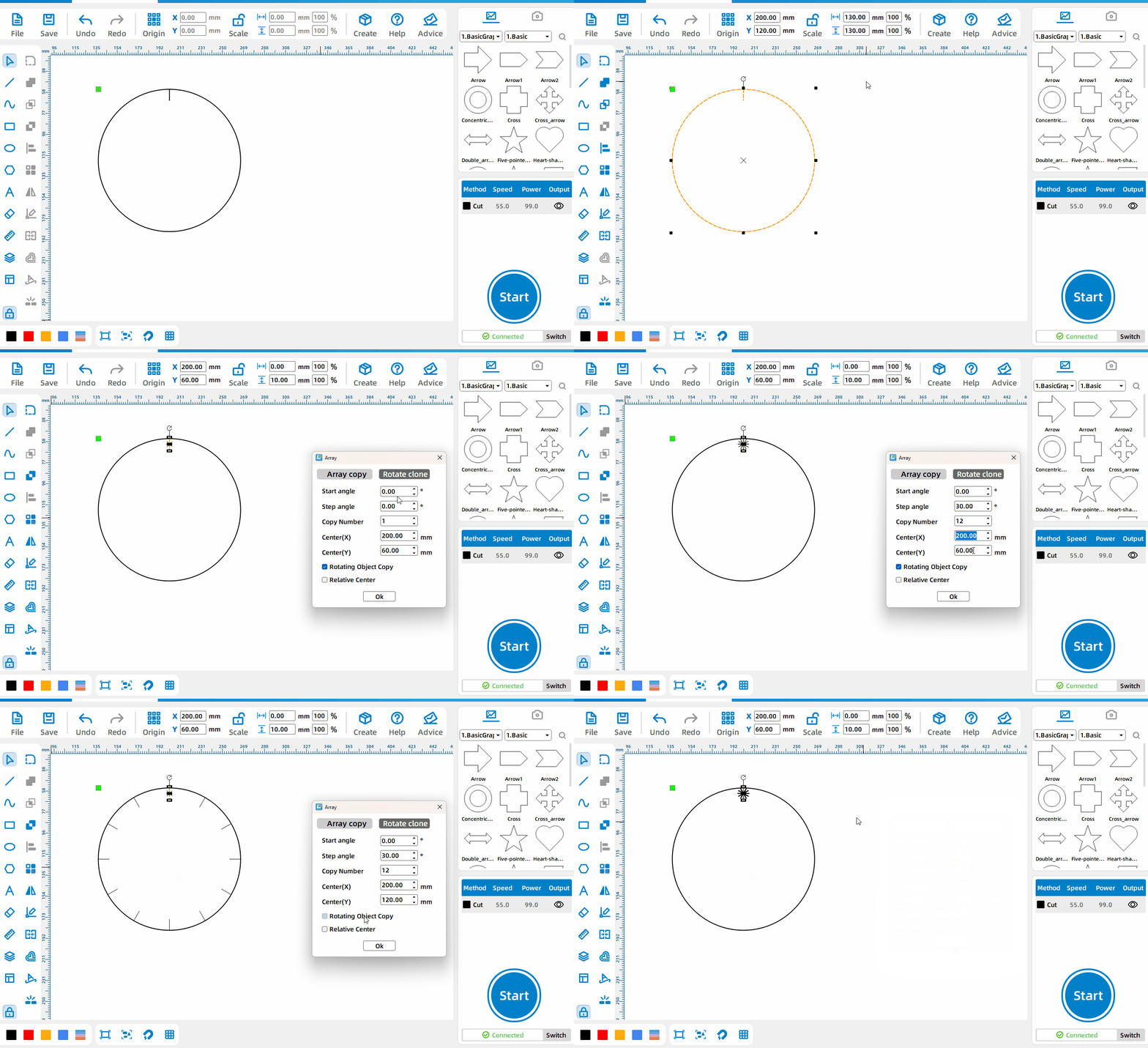
Circular Array
Select [Circular Array] mode and set parameters, where [Start Angle] is the angle between the original primitive and the first primitive obtained from the array in addition to [Array Angle], and [Array Angle] is the angle obtained by each array. The spacing angle between the primitives, [Number of Copies] is the total number obtained after the array, check [Relative Center], and the [Center x] and [Center y] set at this time are the xy coordinates relative to the original primitives , uncheck [Relative Center], the [Center x] and [Center y] set at this time are the xy coordinates relative to the upper left corner of the canvas, and [Rotate copy object] is to rotate the primitives obtained from the array at the array angle.
Mirroring Tool
Horizontal Mirroring
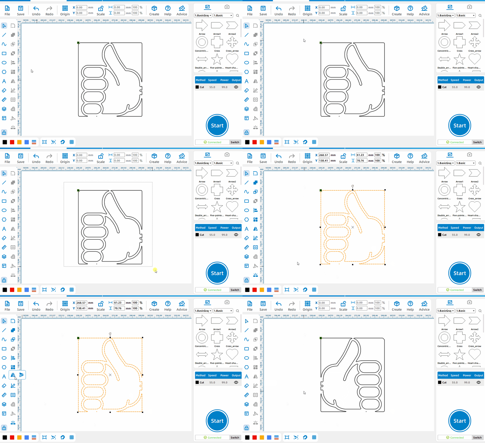
After selecting the pattern, click the horizontal mirror function button.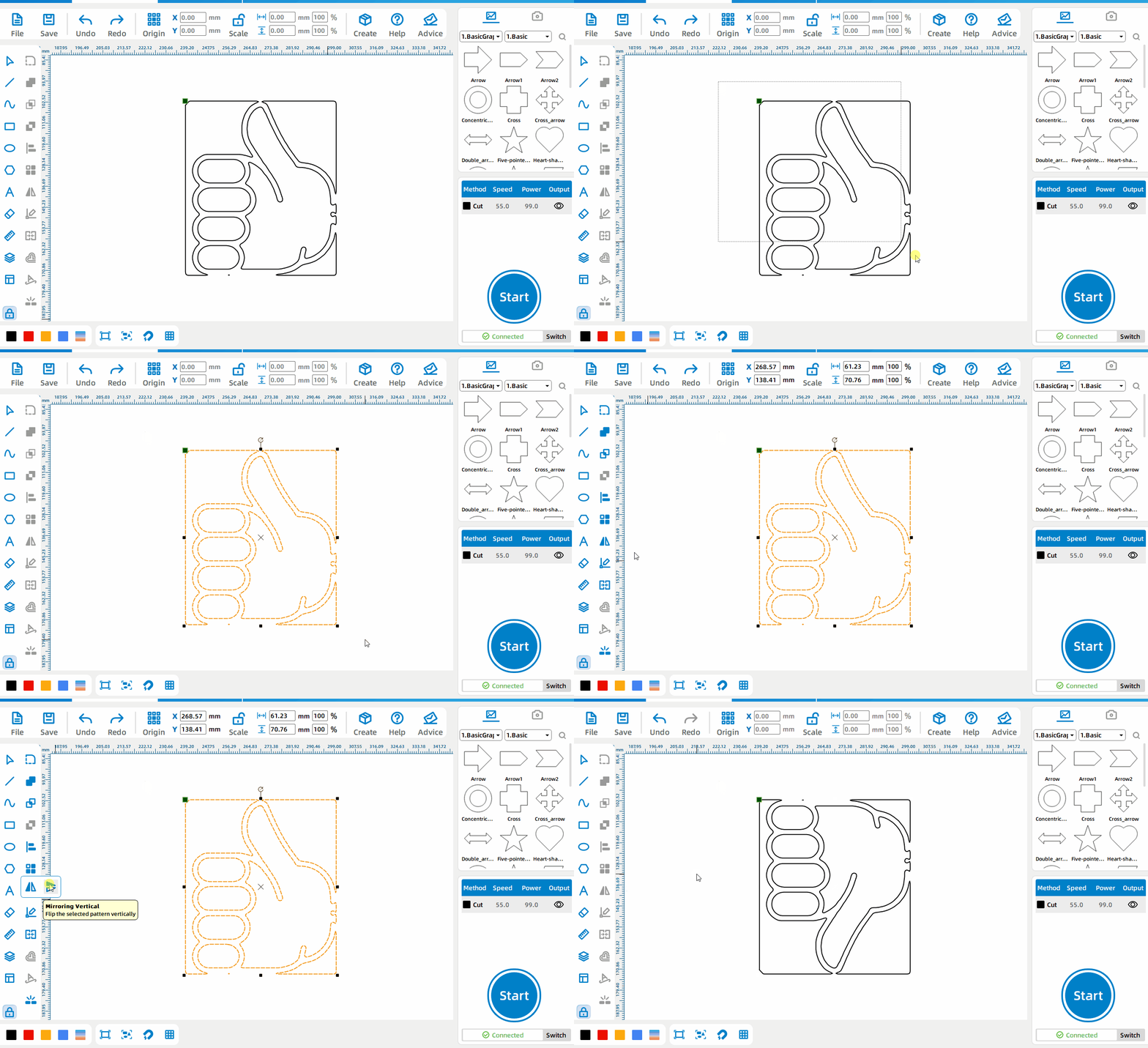
Vertical Mirroring
After selecting the pattern, click the vertical mirror function button.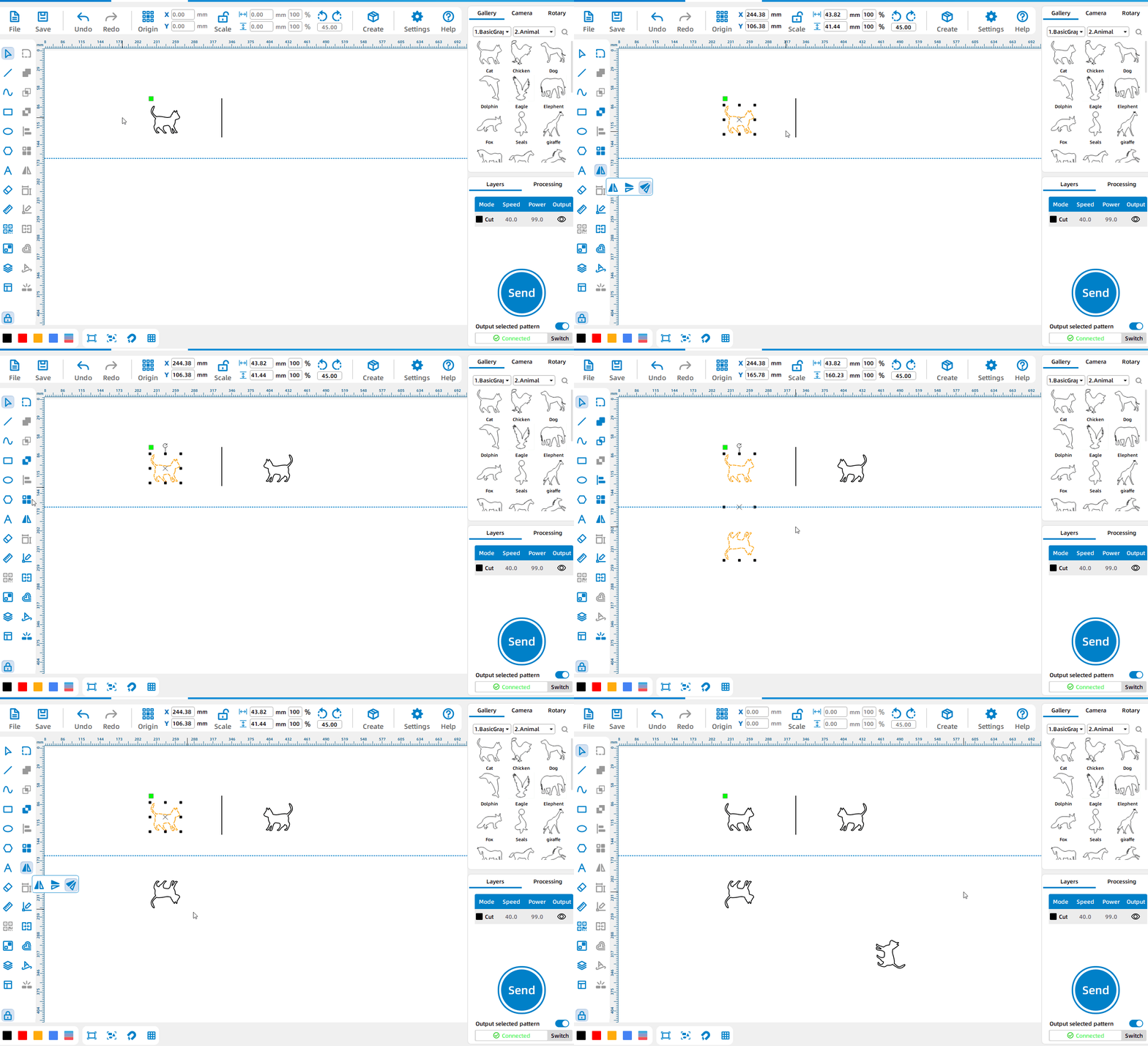
Axis mirroring
Select the pattern, left-click the [Mirror Tool] with the left mouse button, select [Axis mirroring], use a straight line, reference line or two points as the mirror line to generate a new mirrored pattern.
Node Editing
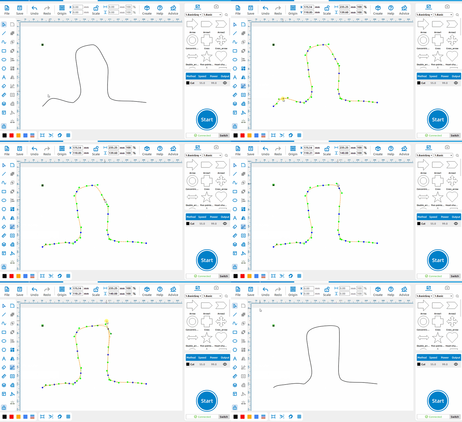
Node editing
Select the primitive, Left-click [Node Edit], change the position of the node by moving the blue node, and drag the green handle to change the shape of the curve.
Combination Curve
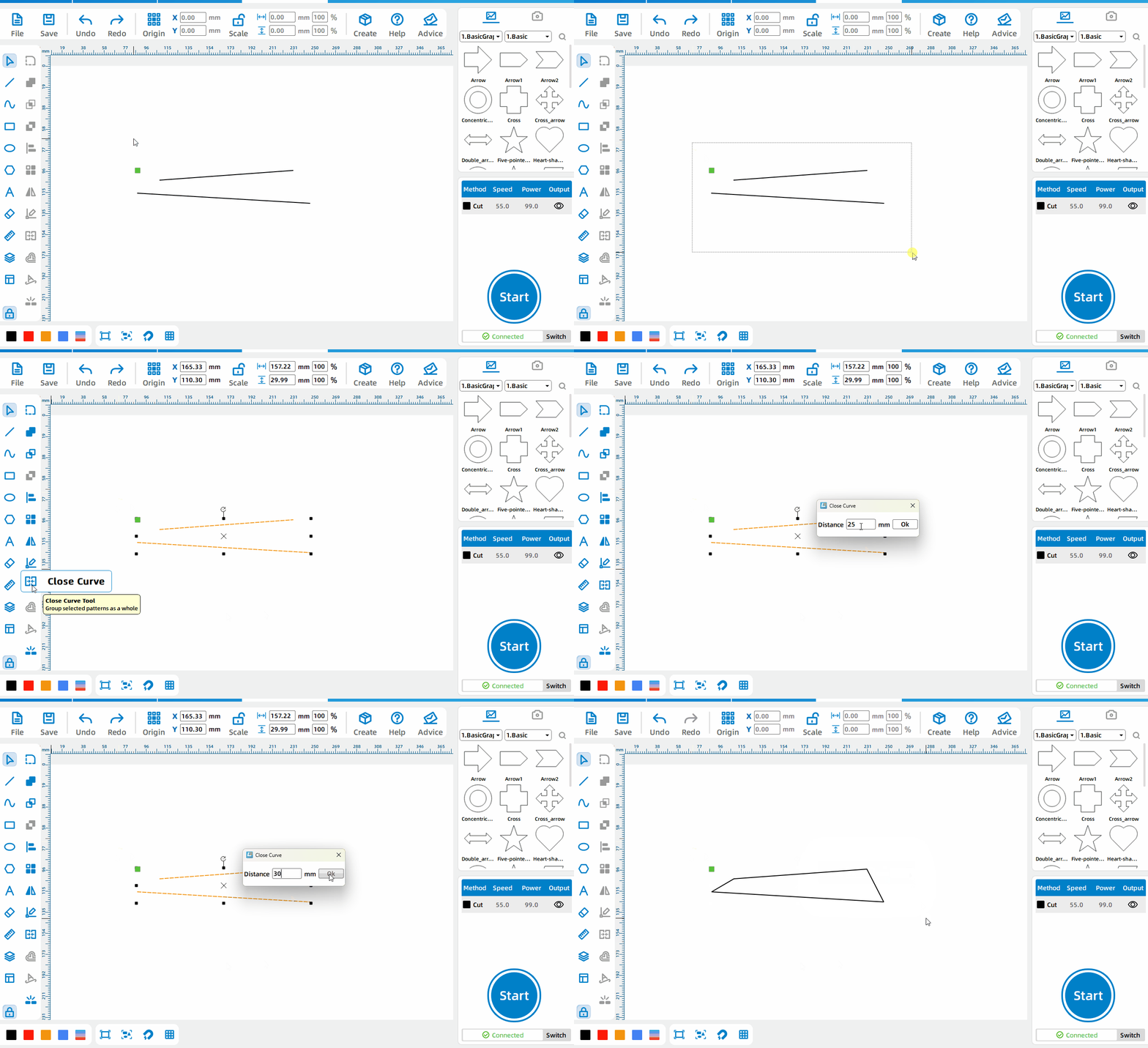
Combination curve
Select two curves, estimate the size of the opening, and set [center distance].
Smart Adding Tabs
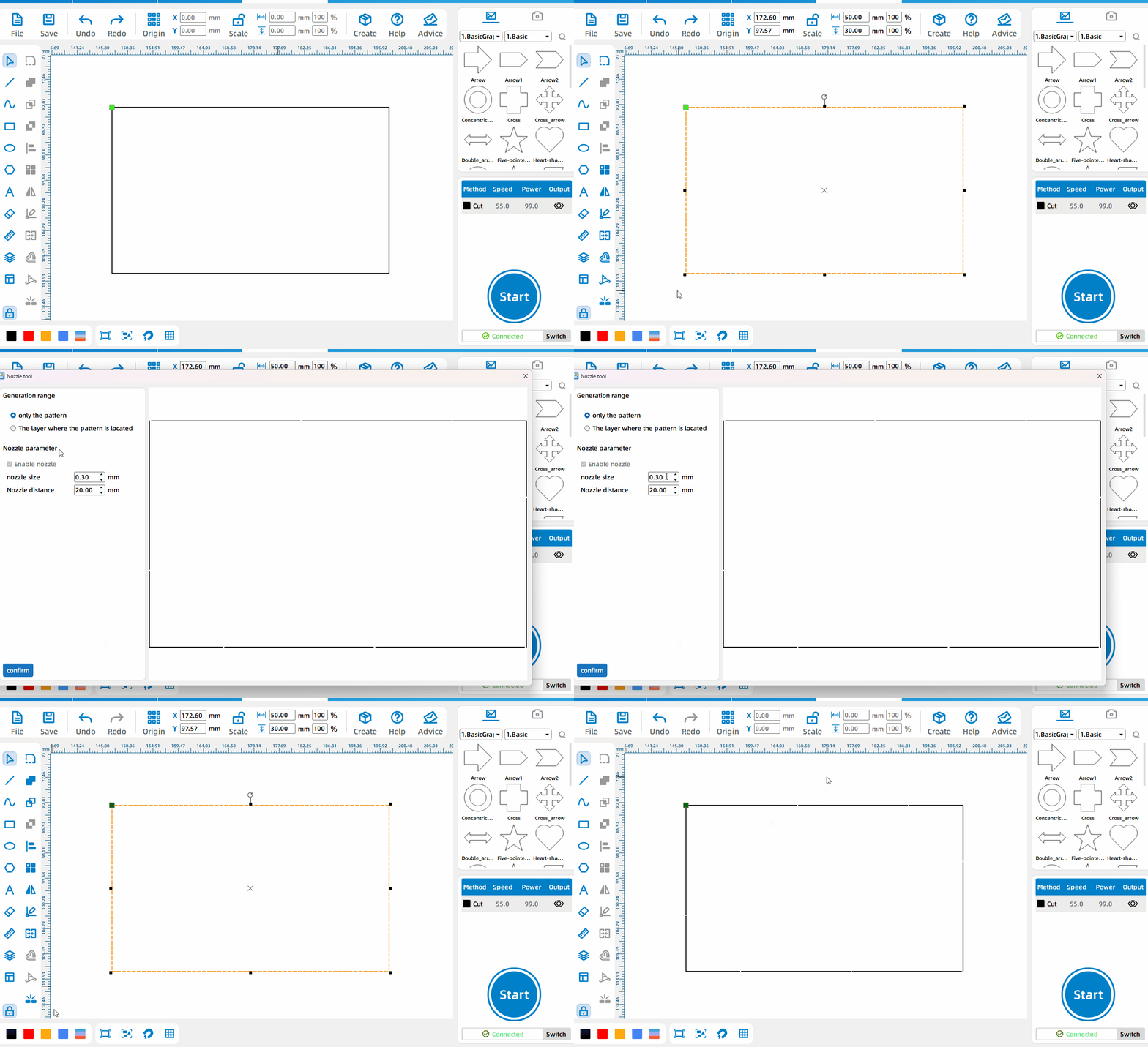
Generate a nozzle according to the selected pattern
Select the primitive to generate the nozzle, select [Only this pattern] mode, and set the parameters.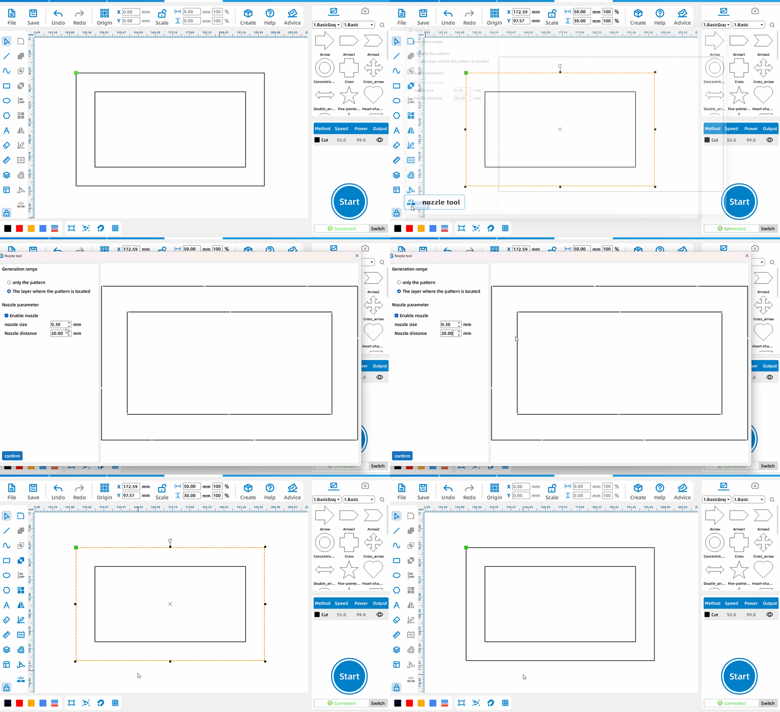
Generate water outlet by layer
Select any element in the layer where the nozzle is to be generated, select the [layer where the pattern is located] mode, and set the parameters. Note that the nozzle generated in this mode will not be displayed on the canvasSelect any element in the layer where the nozzle is to be generated, select the [layer where the pattern is located] mode, and set the parameters. Note that the nozzle generated in this mode will not be displayed on the canvas.
Coordinate Editing
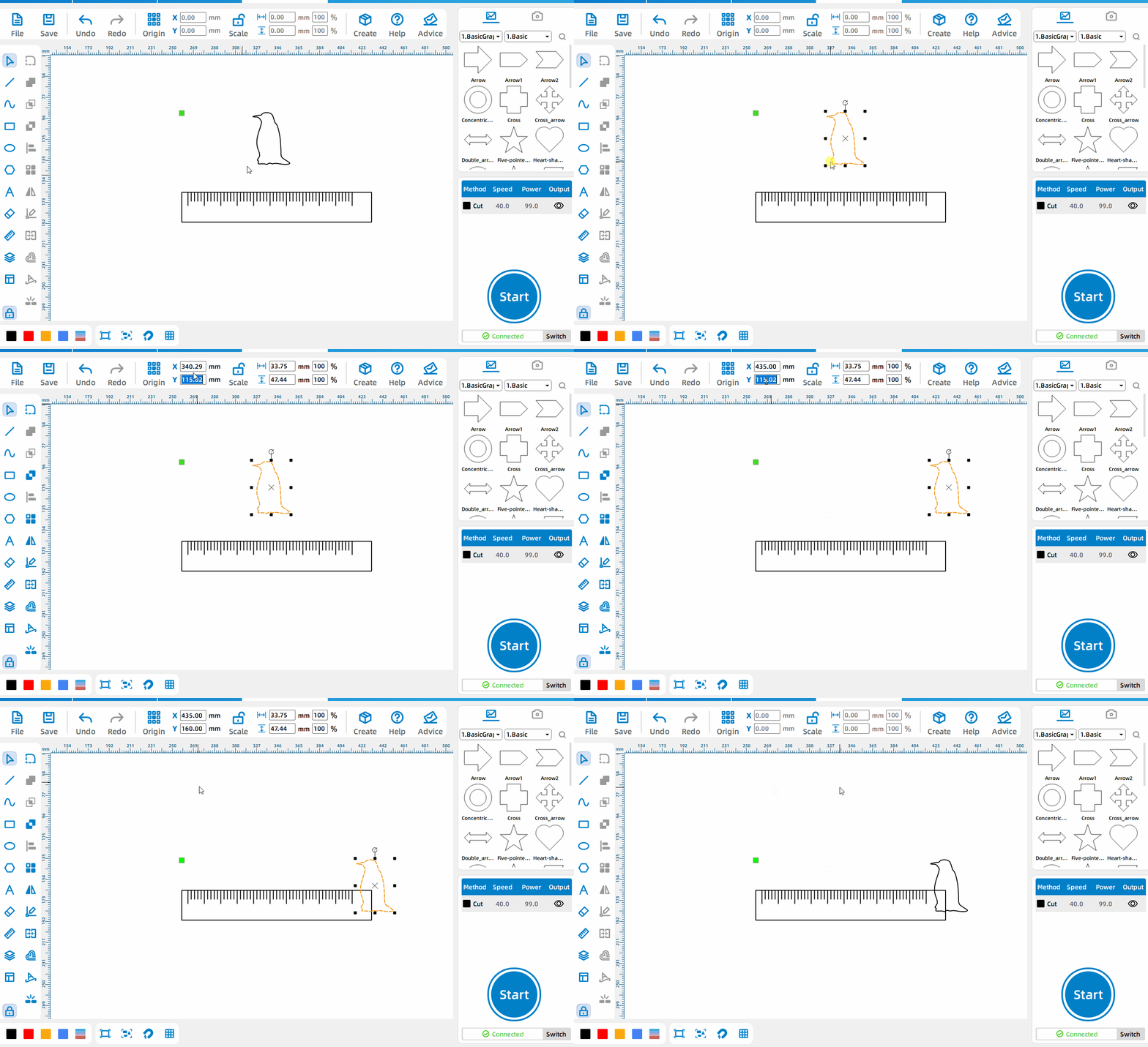
Set pattern position
After selecting the pattern, change the values of the X and Y input boxes on the toolbar to set the exact position of the pattern.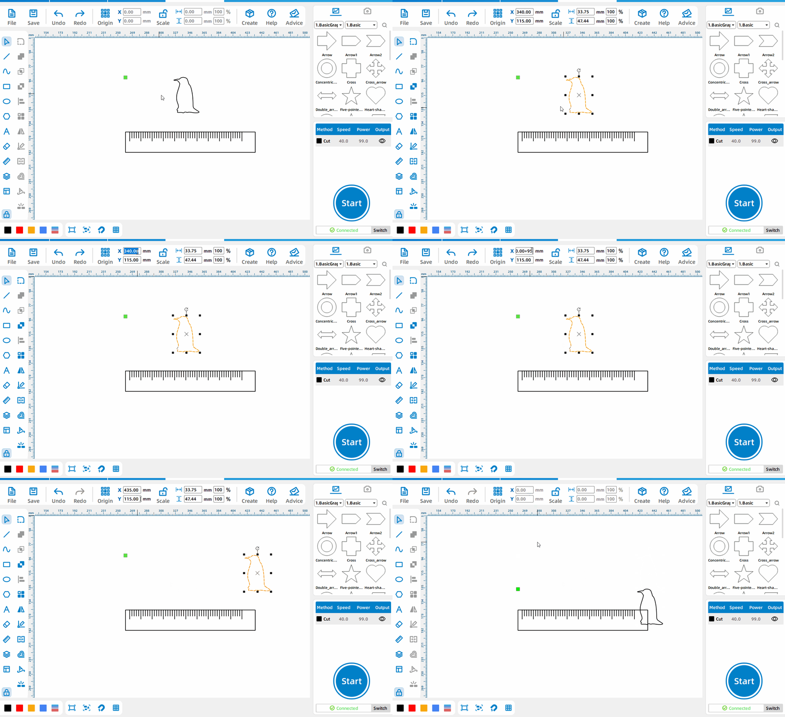
Pattern moves specified distance
Enter the four arithmetic formulas in the X and Y input boxes on the toolbar to move the pattern a specific distance.
Size Editing
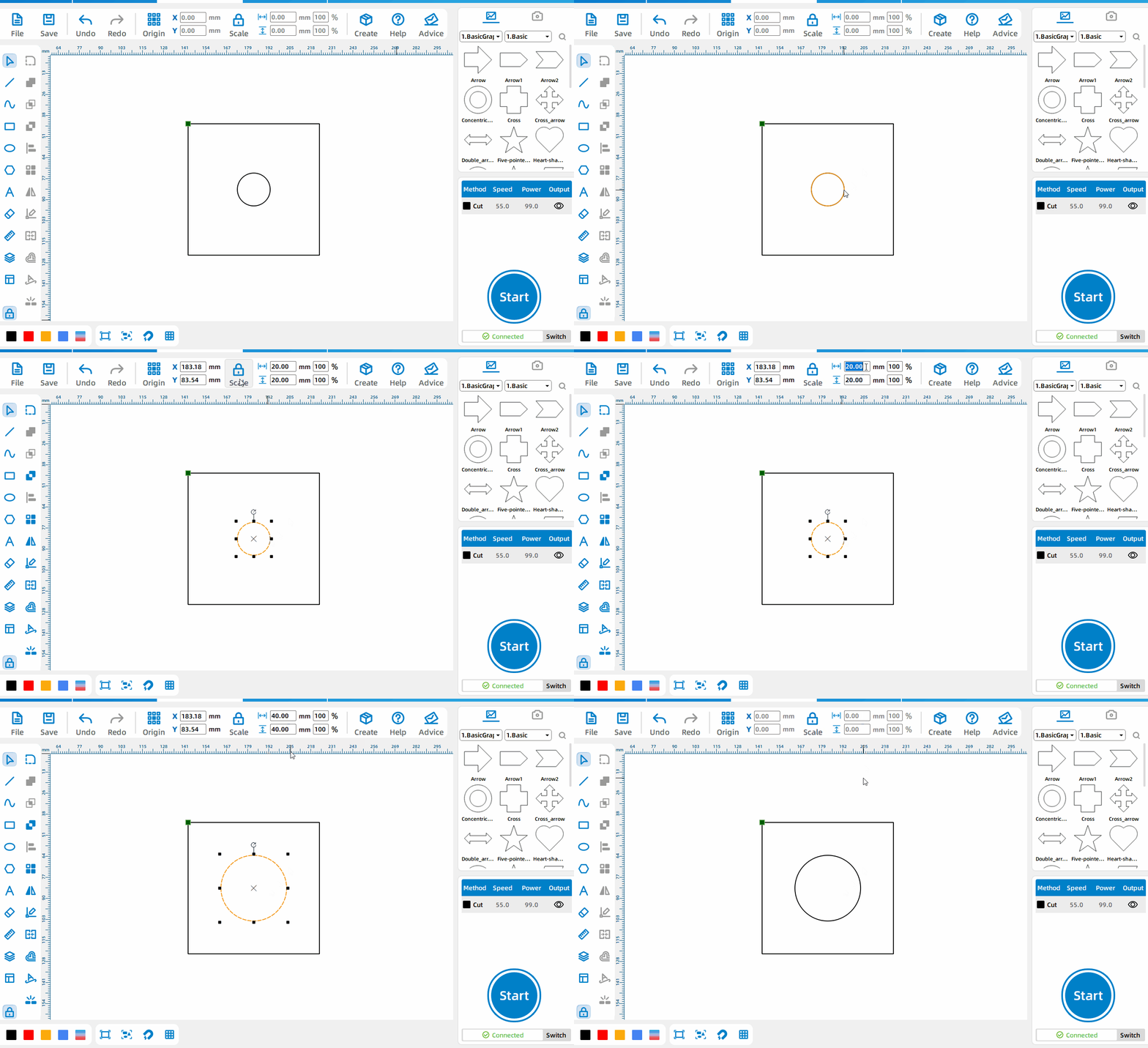
Set the pattern size proportionally
Enter values in the toolbar length and width input boxes to set the pattern size proportionally.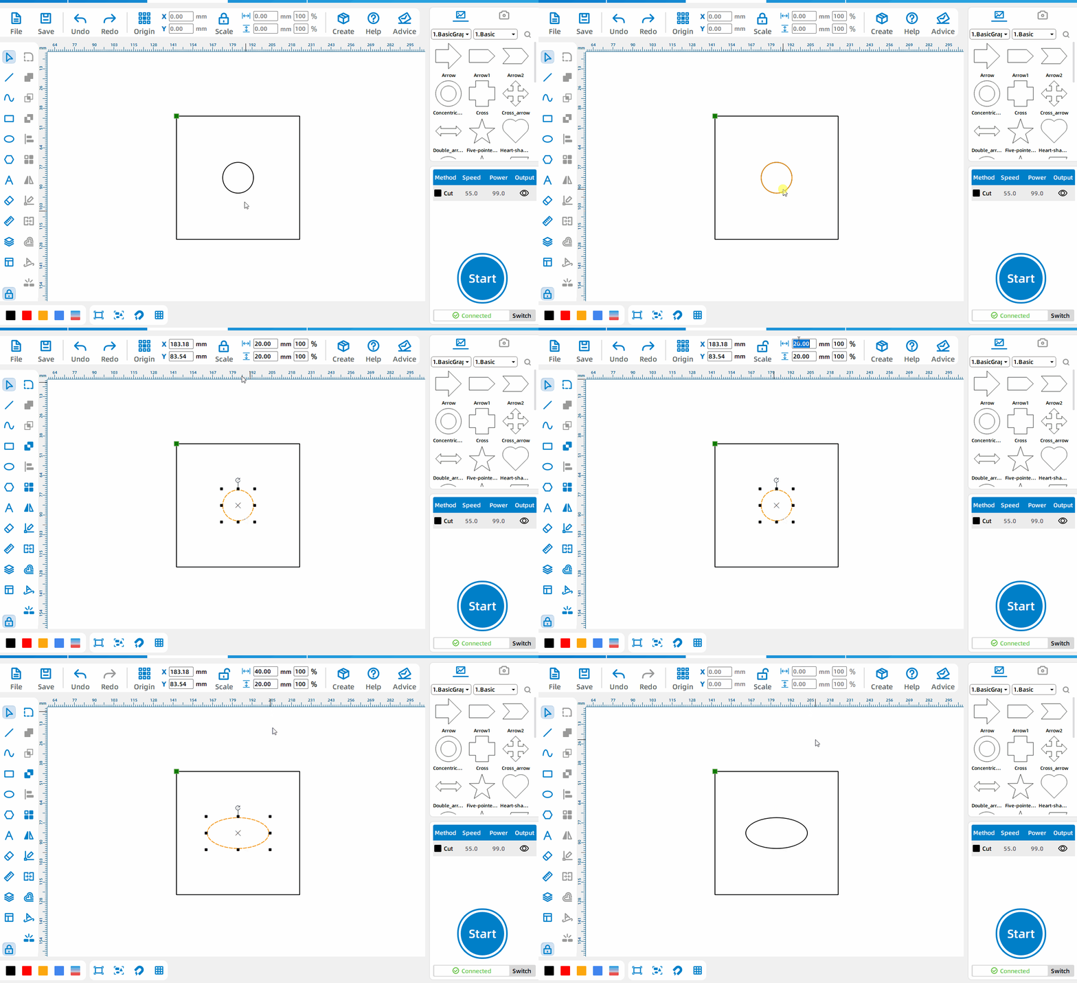
Set pattern size non-proportionally
After unlocking the [Equal Ratio] button, enter values in the toolbar length and width input boxes to set.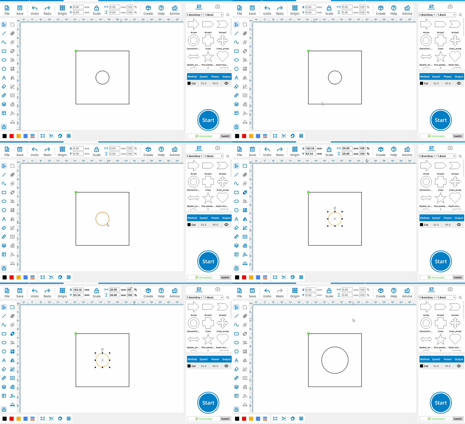
Set the zoom multiple
Set the zoom multiple of the pattern in the percentage input box.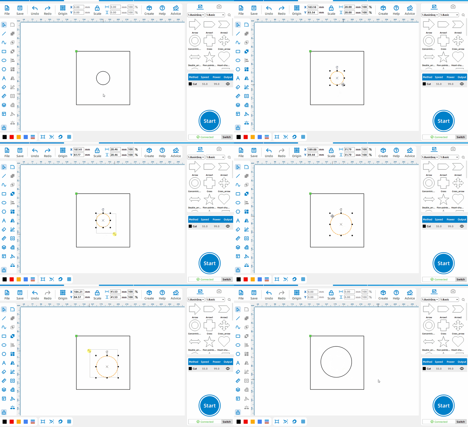
Drag proportionally to set the pattern size
After selecting the pattern, drag the four black dots in the diagonal corners to set the pattern size in equal proportions.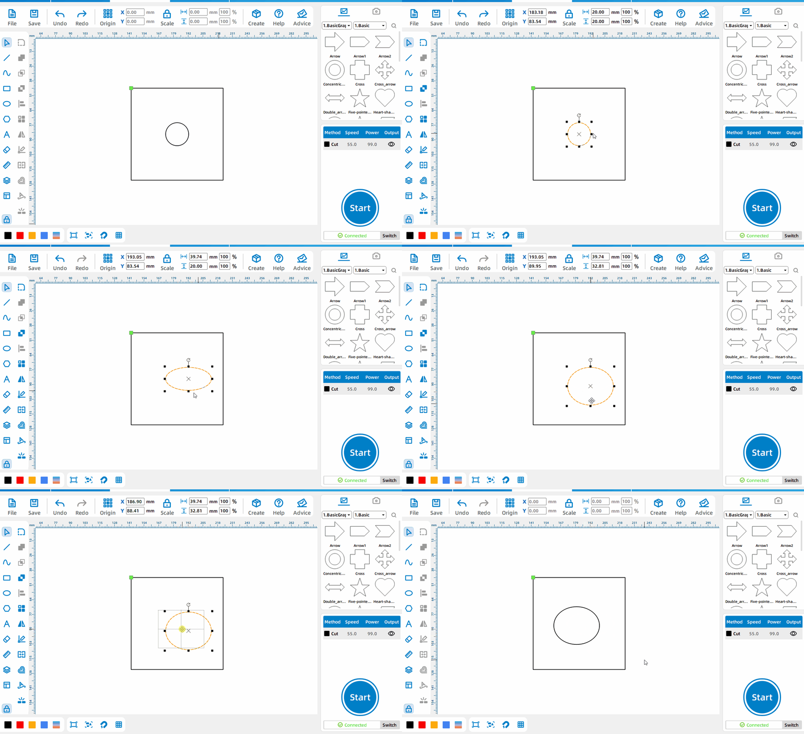
Drag non-proportionally to set pattern size
After selecting the pattern, drag the four black dots at the midpoint of the border to set the size of the pattern.
Offset Shape
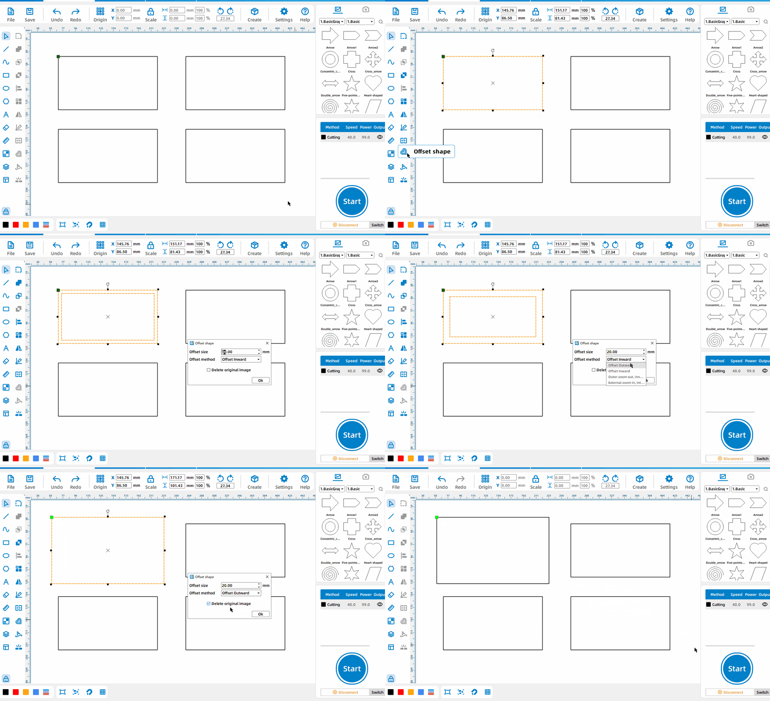
Offset shape
Select the pattern, left-click [Offset shape] , set the offset size, offset direction, and whether to delete the original image.
Text Path
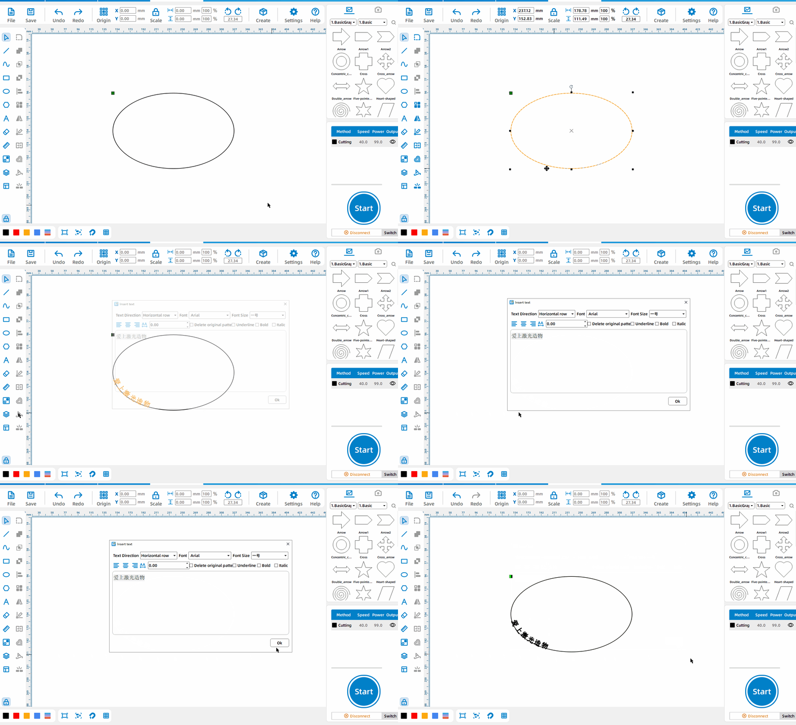
Draw Text Following Path
Select the pattern, left-click [Text Path], and the generated text can follow the path.
Pattern Properties
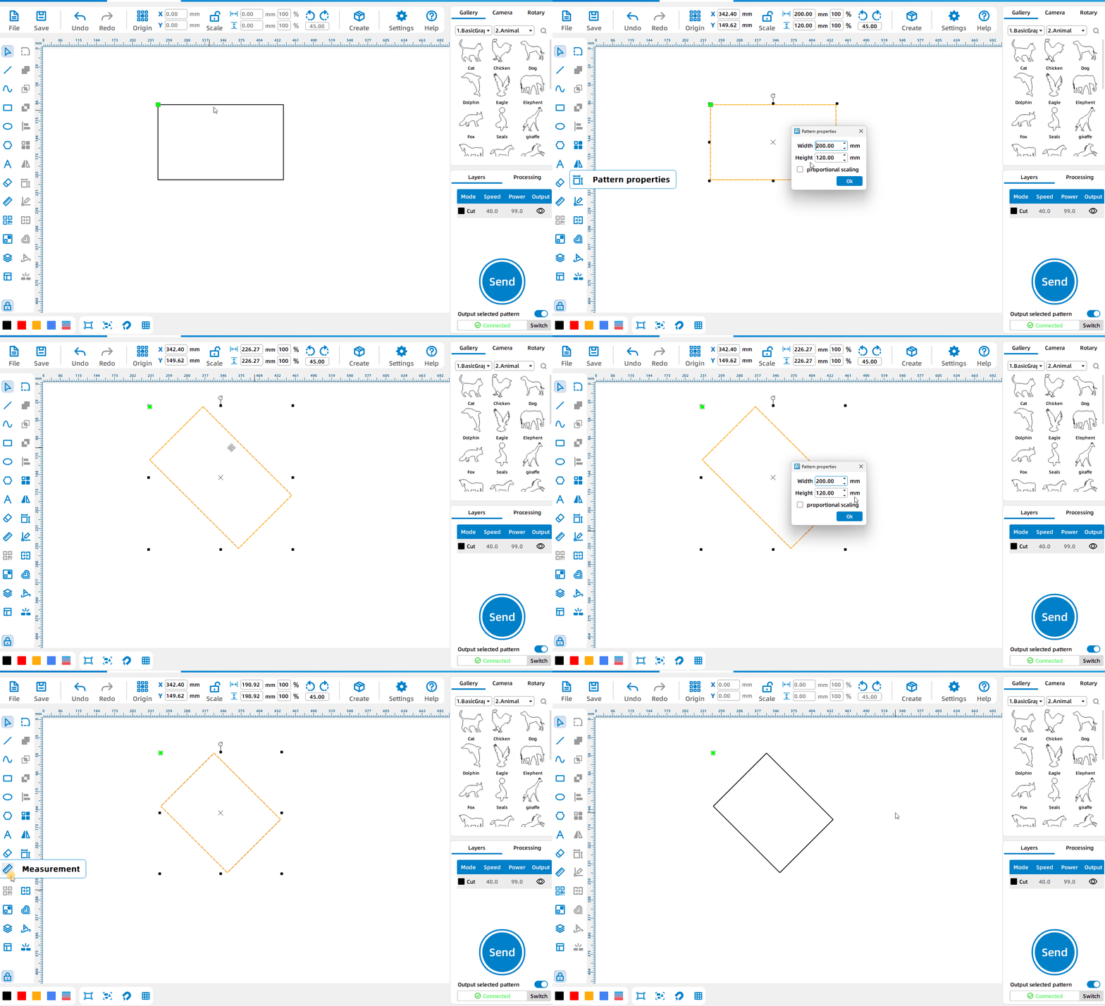
Modify the width and height of the rotated element
After the pattern is rotated, the width and height attributes remain unchanged; you can modify the specific width and height after the rotation of the element in [Pattern Properties].
Featured Tools
Camera
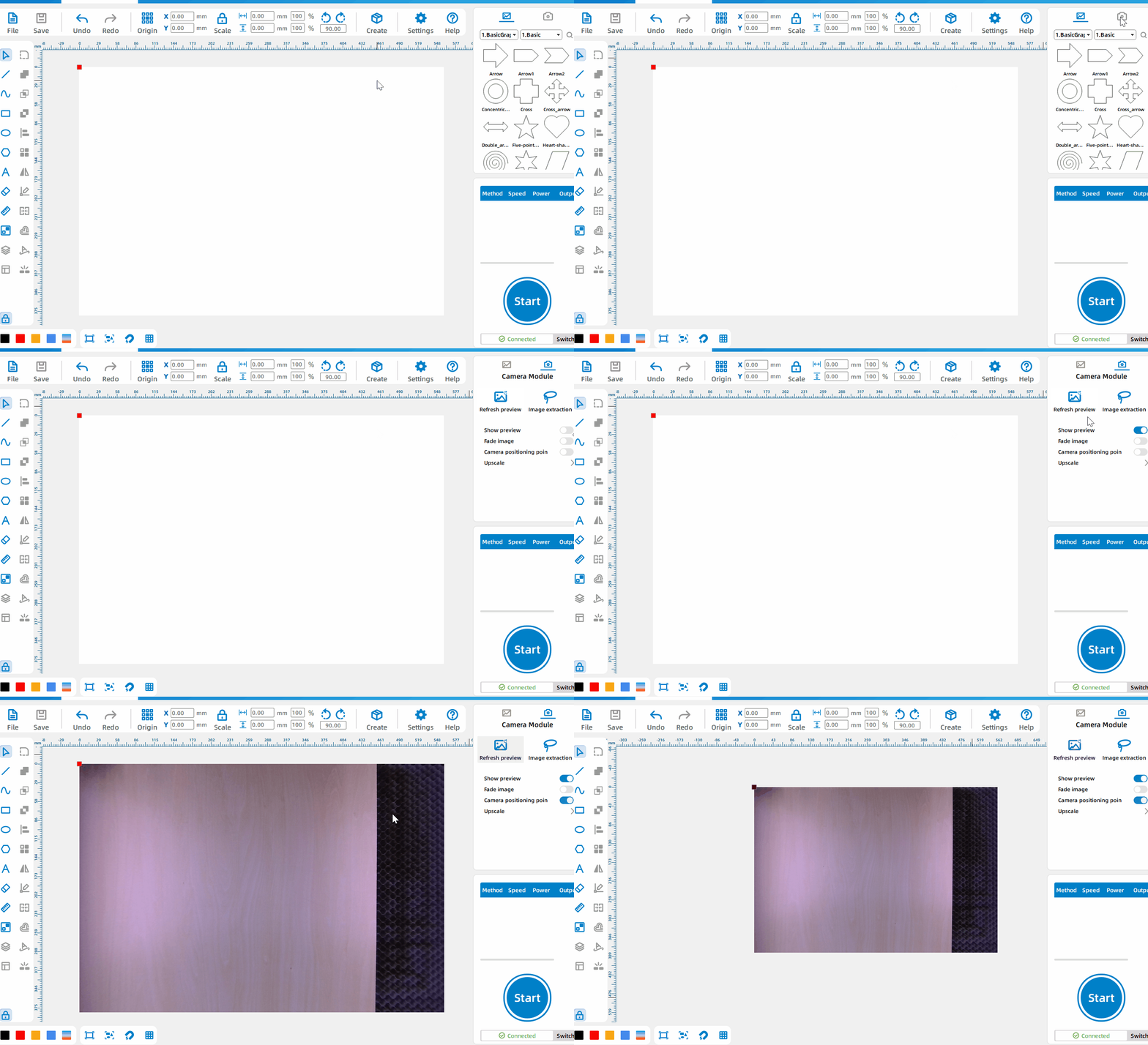
Real-time preview of processing platform status
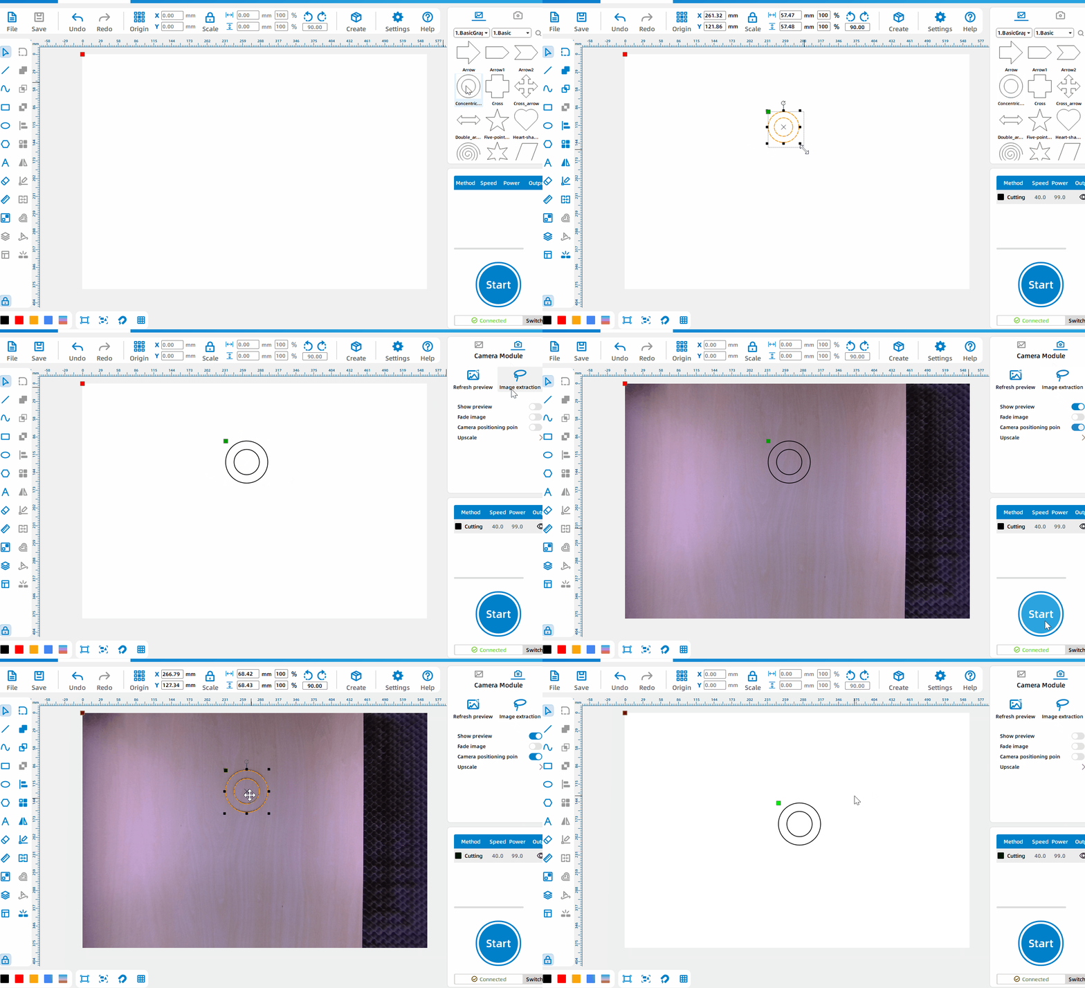
Click the camera icon and left-click [Refresh Preview] to preview the processing platform status in real time.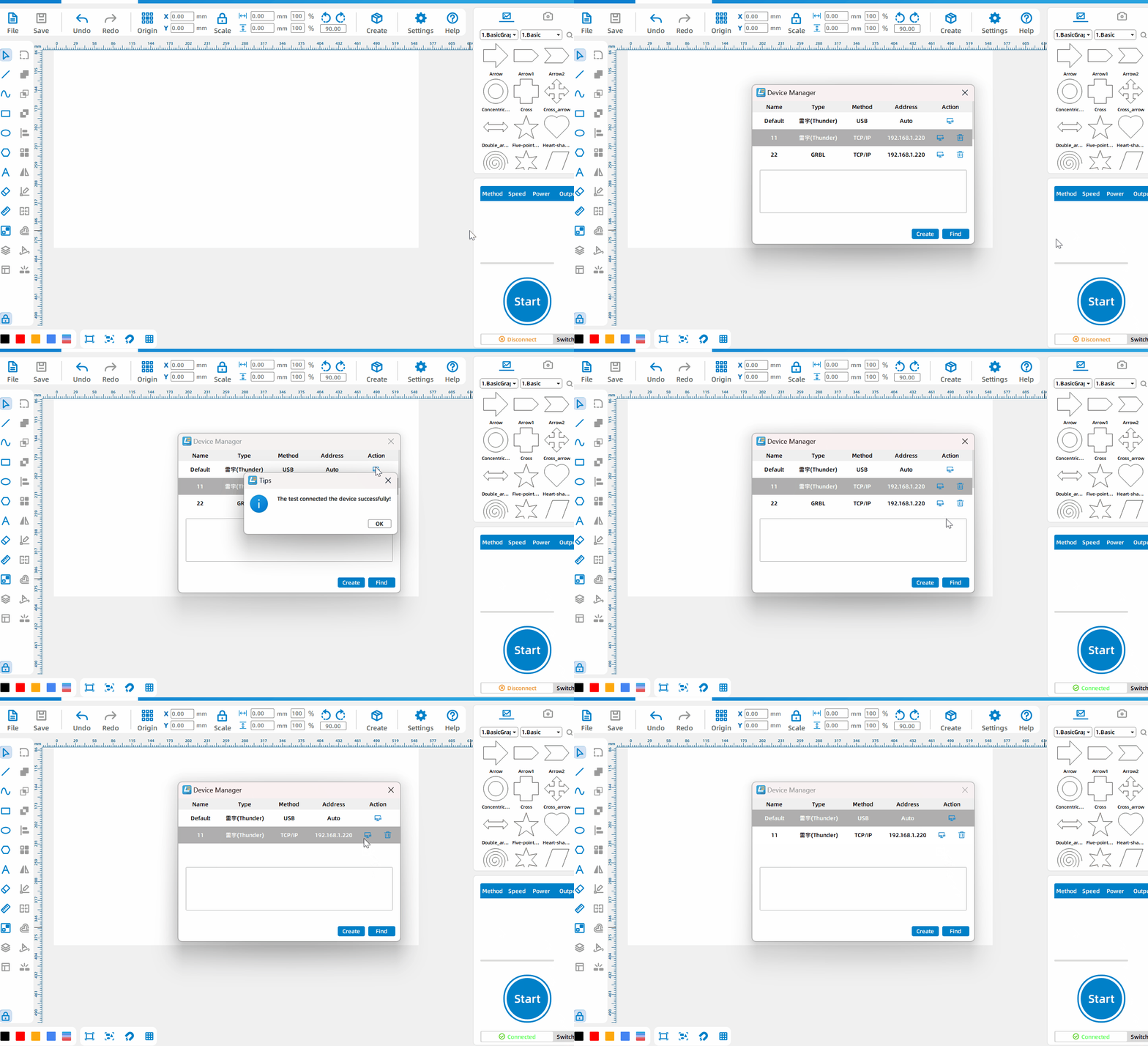
Accurate Positioning And Processing
After refreshing the preview, the processing platform photo is displayed on the canvas. You can draw the graphics at any position and process it at the corresponding position of the processing platform in the device.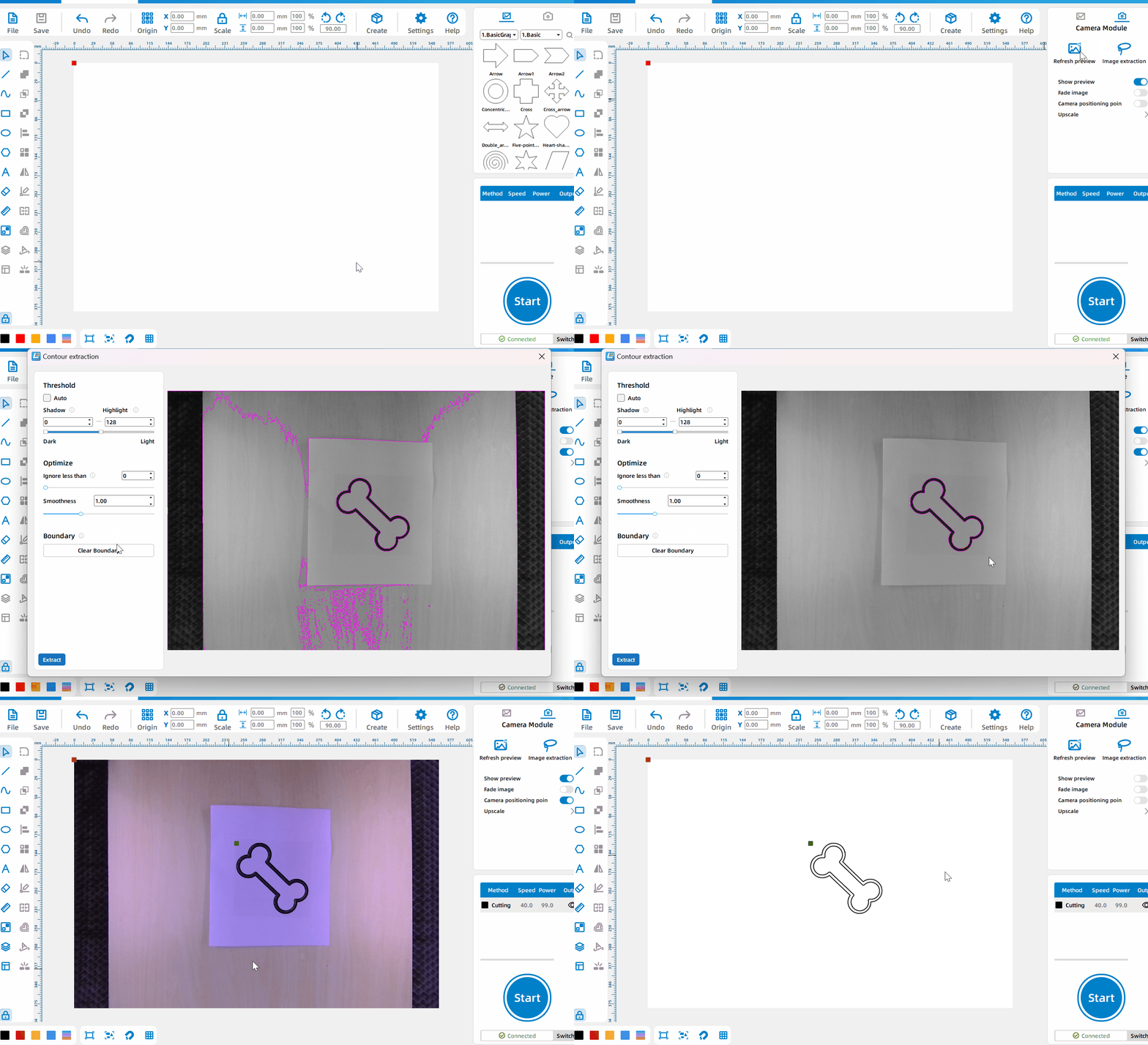
Image Extraction
Click the camera icon and left-click [image extraction] to extract the contour of the primitive or object processed by the processing platform.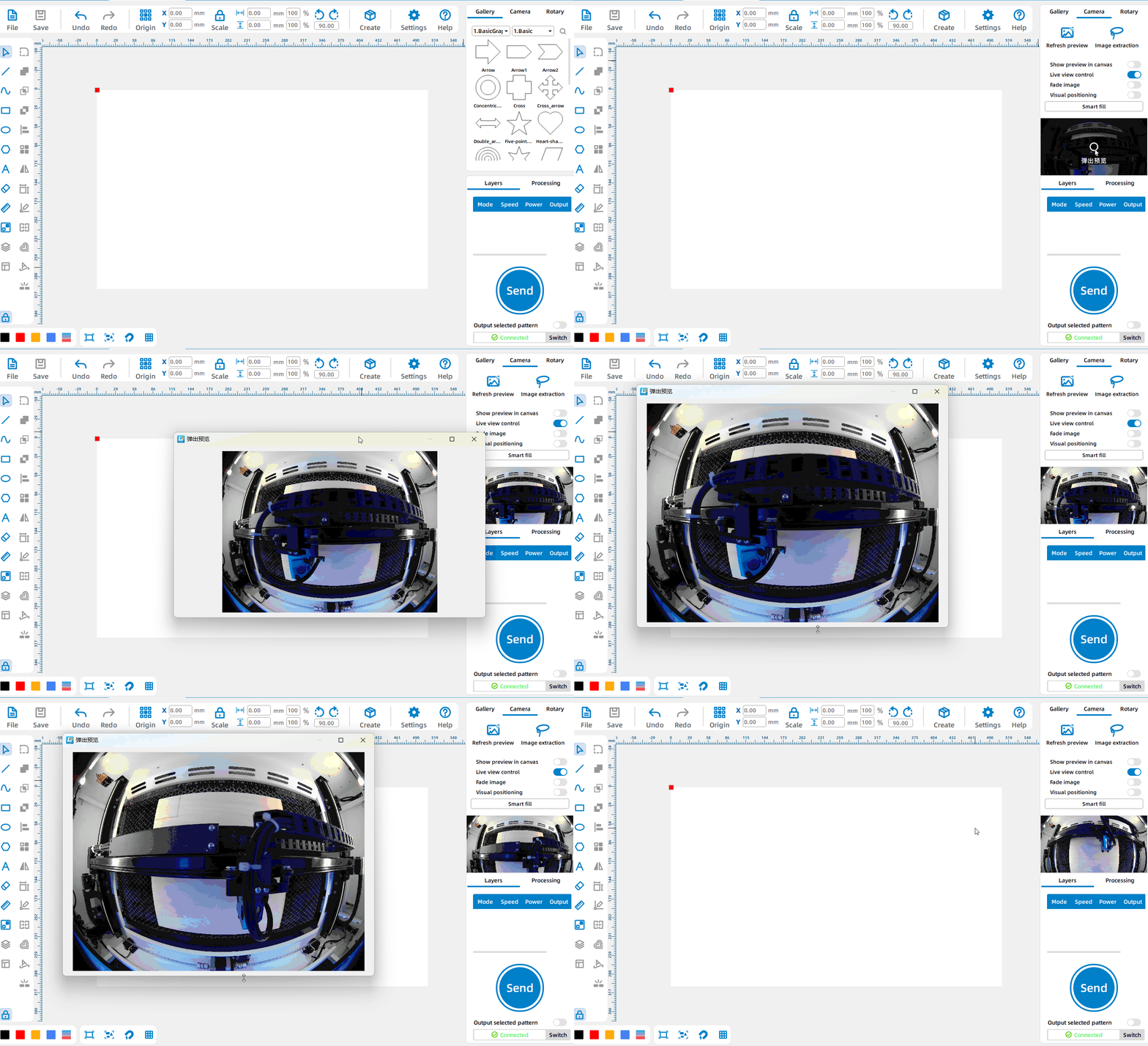
Remote monitoring of processing
Click [Camera], then turn on [Live view control] to remotely monitor the processing platform; click [Monitoring Screen] to pop up an independent window and enlarge the monitoring screen.
Creation
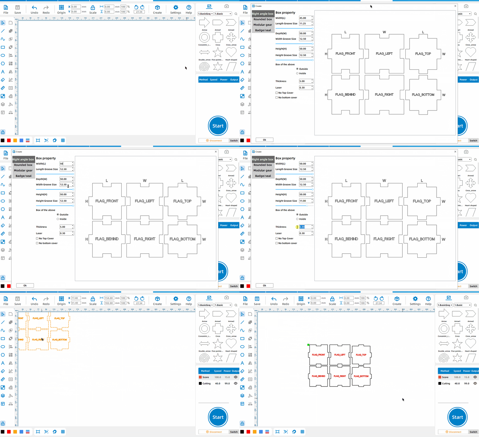
Right Angle Box
Left-click the [Create], select [Rectangular Box], set the length, width, height, groove size, and material thickness.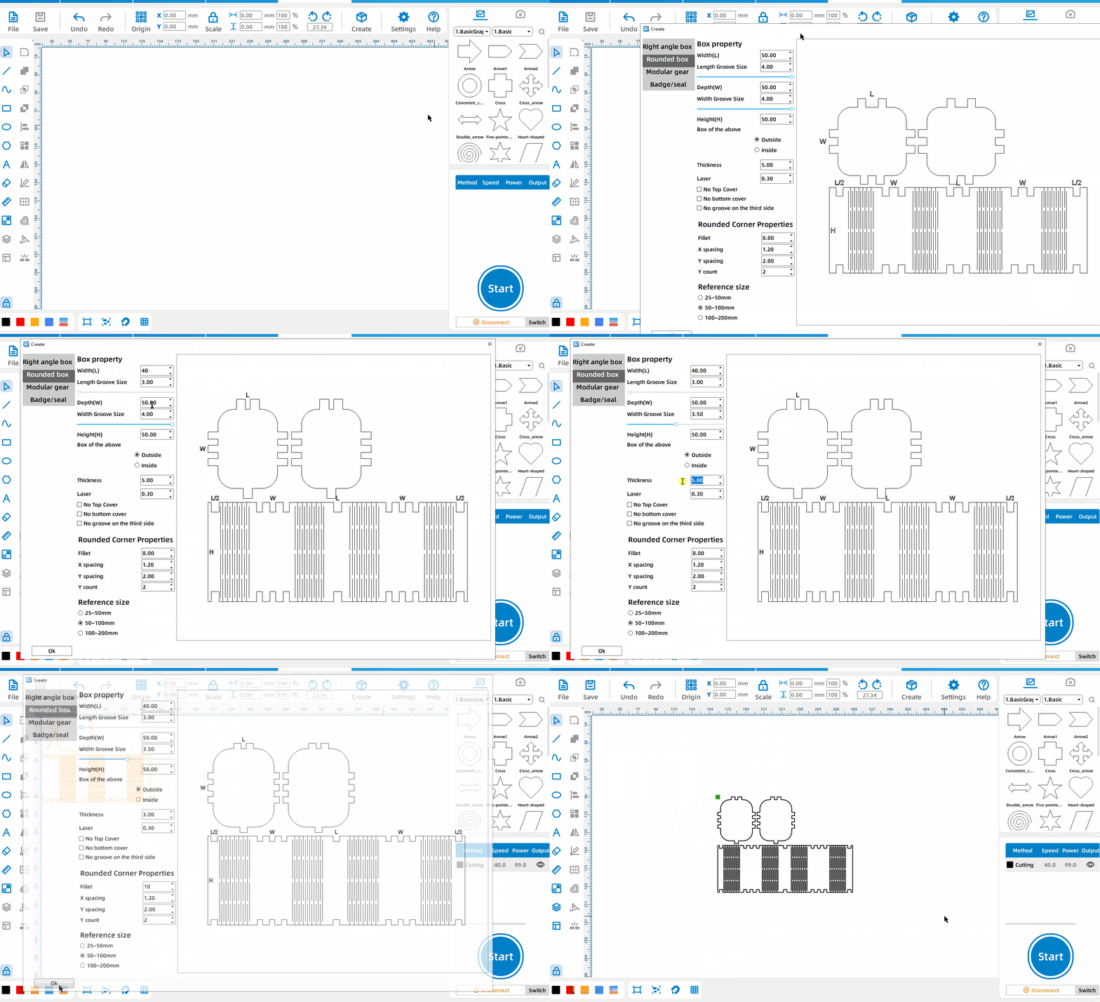
Rounded Corner Box
Left-click the [Create], select [Rounded Corner Box], set the length, width, height, groove size, material thickness, and rounded corner properties.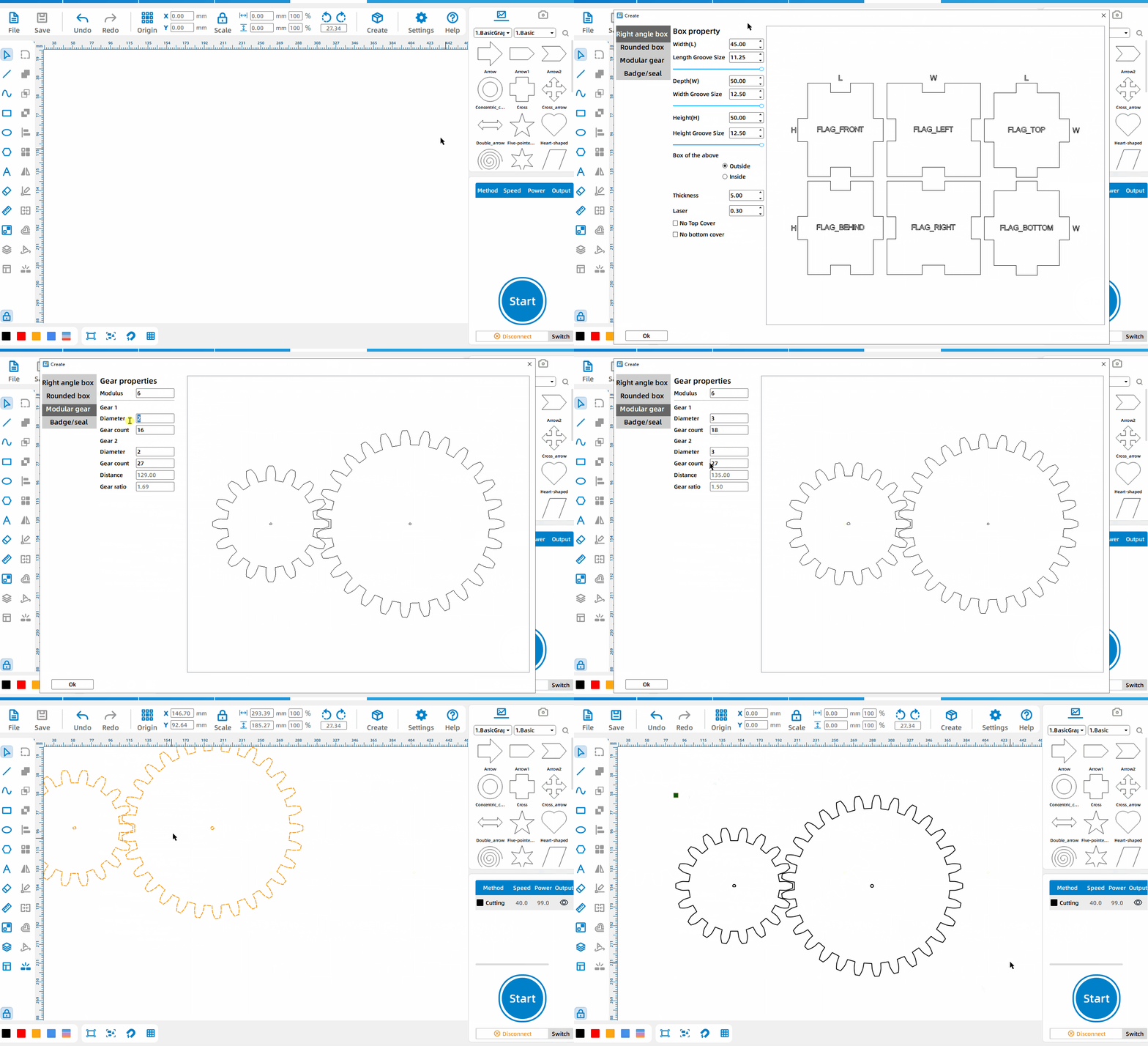
Modulus Gear
Left-click the [Create], select [Modulus Gear], set the modulus, the diameter of the two gears and the number of gears.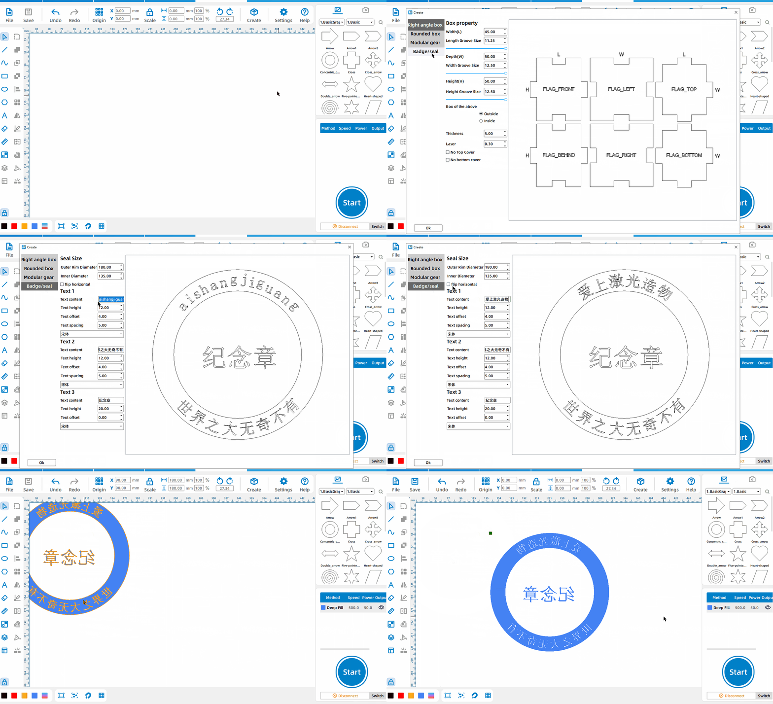
Badge/Seal
Left-click the [Create], ,select [Badge/Seal], and set three text contents; the default is badge, click [Flip Horizontal] to turn it into a seal.
Image Processing
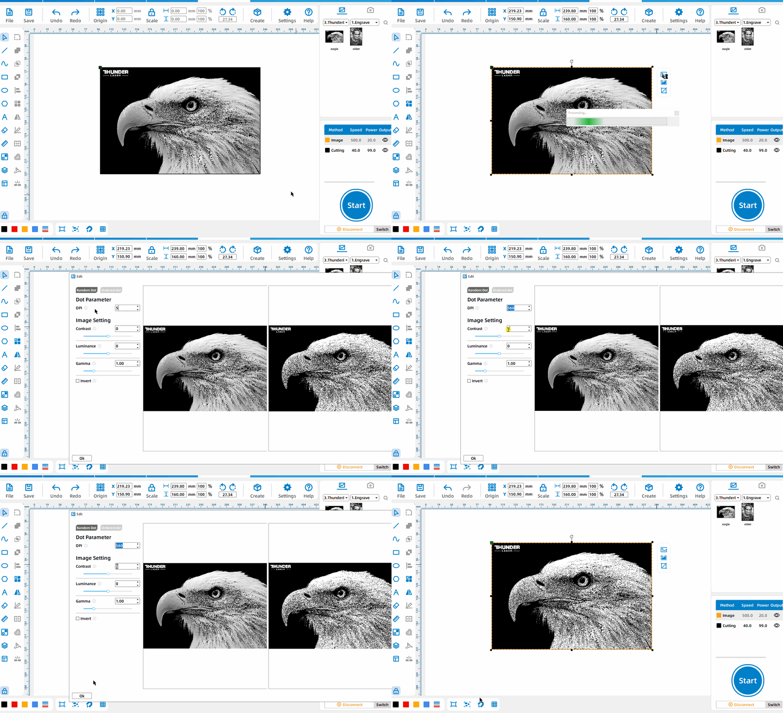
Image Operation
Left-click the image, select [Image Operation], and set the dot matrix parameters and image parameters.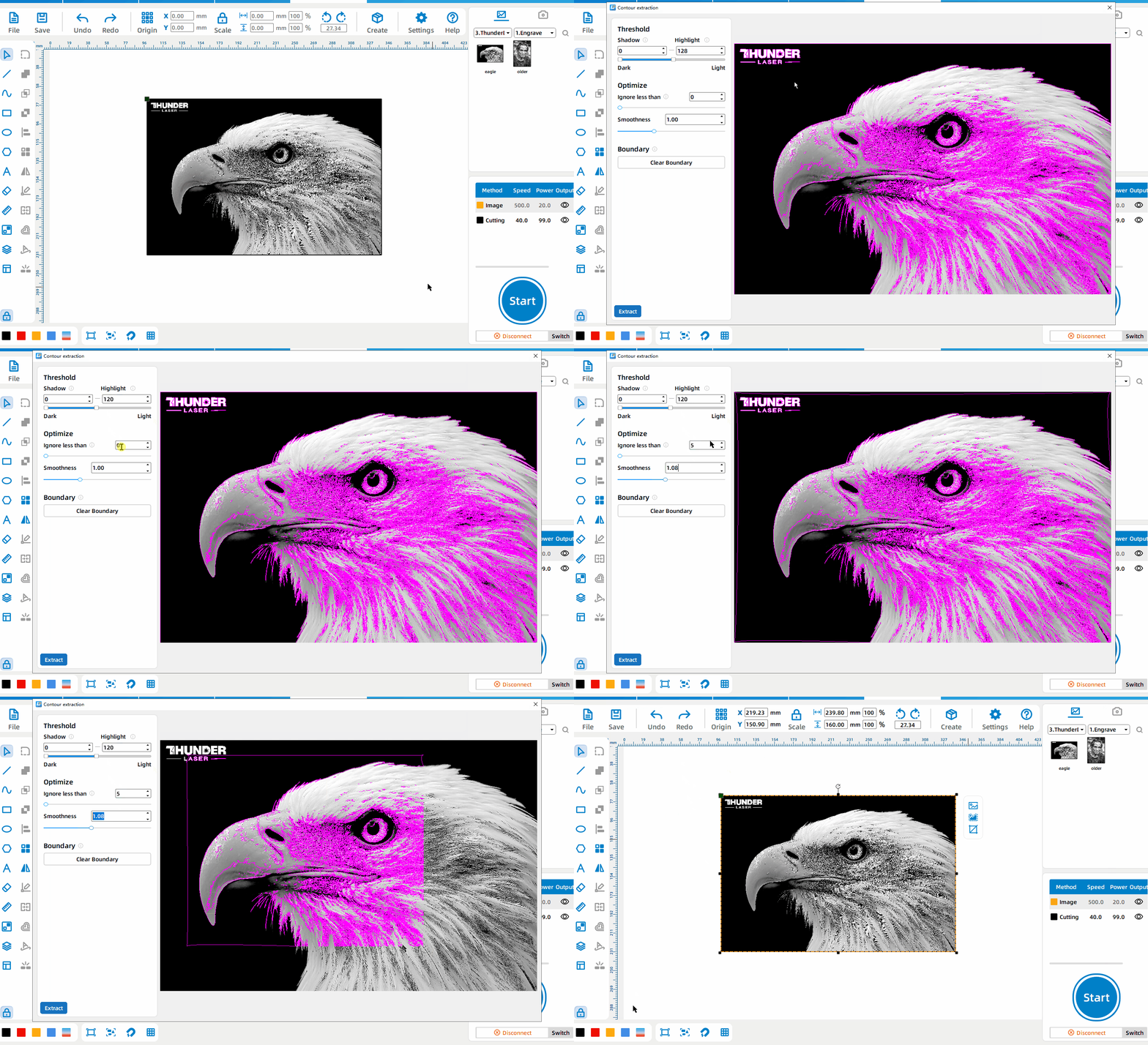
Image Extraction
Left-click the image, select [Image Extraction], set the boundaries between dark and bright areas, ignore small areas, and curve smoothness; press and drag the left mouse button to select the image area to be extracted, and click [Cancel Selection] to restore the extraction of the entire image.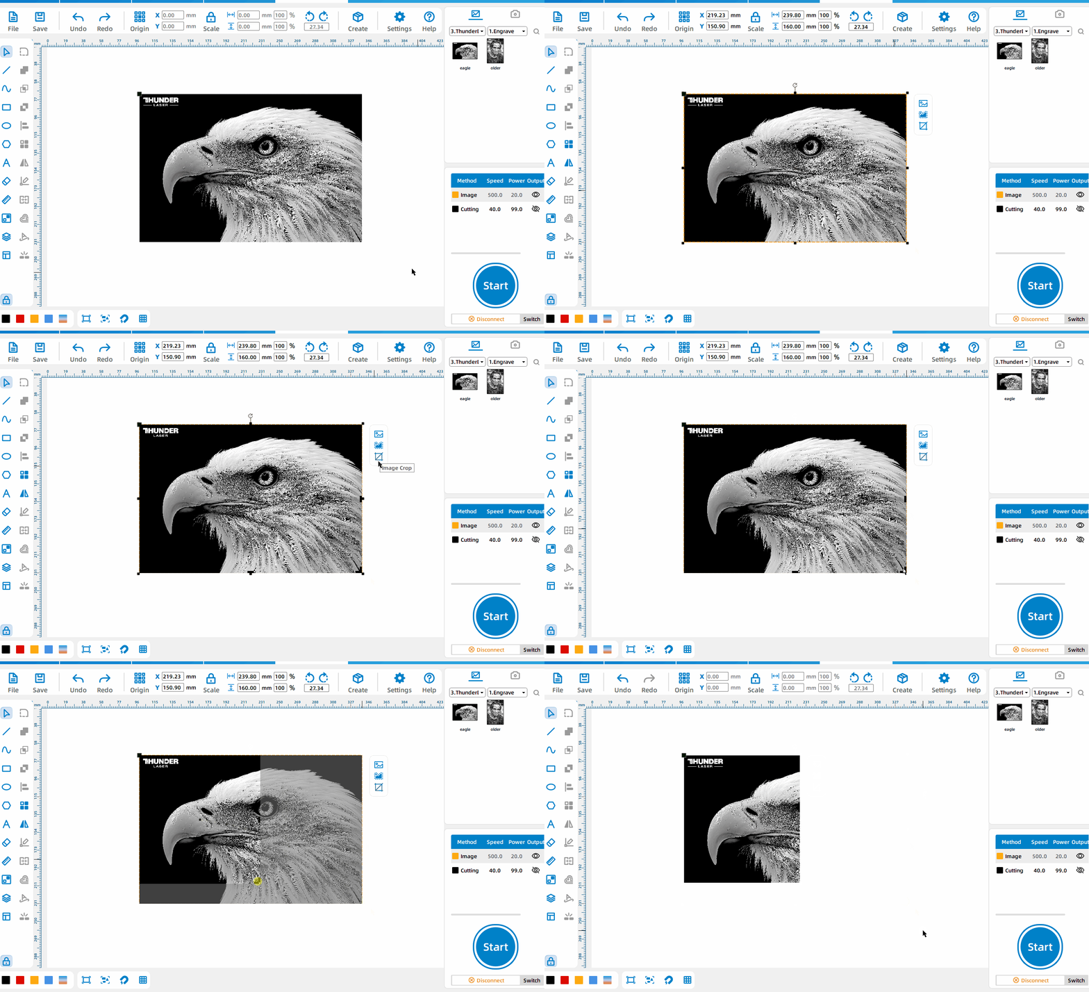
Image Crop
Left-click the image, select [Image Crop], and drag the black edge to change the image size.
Job Management
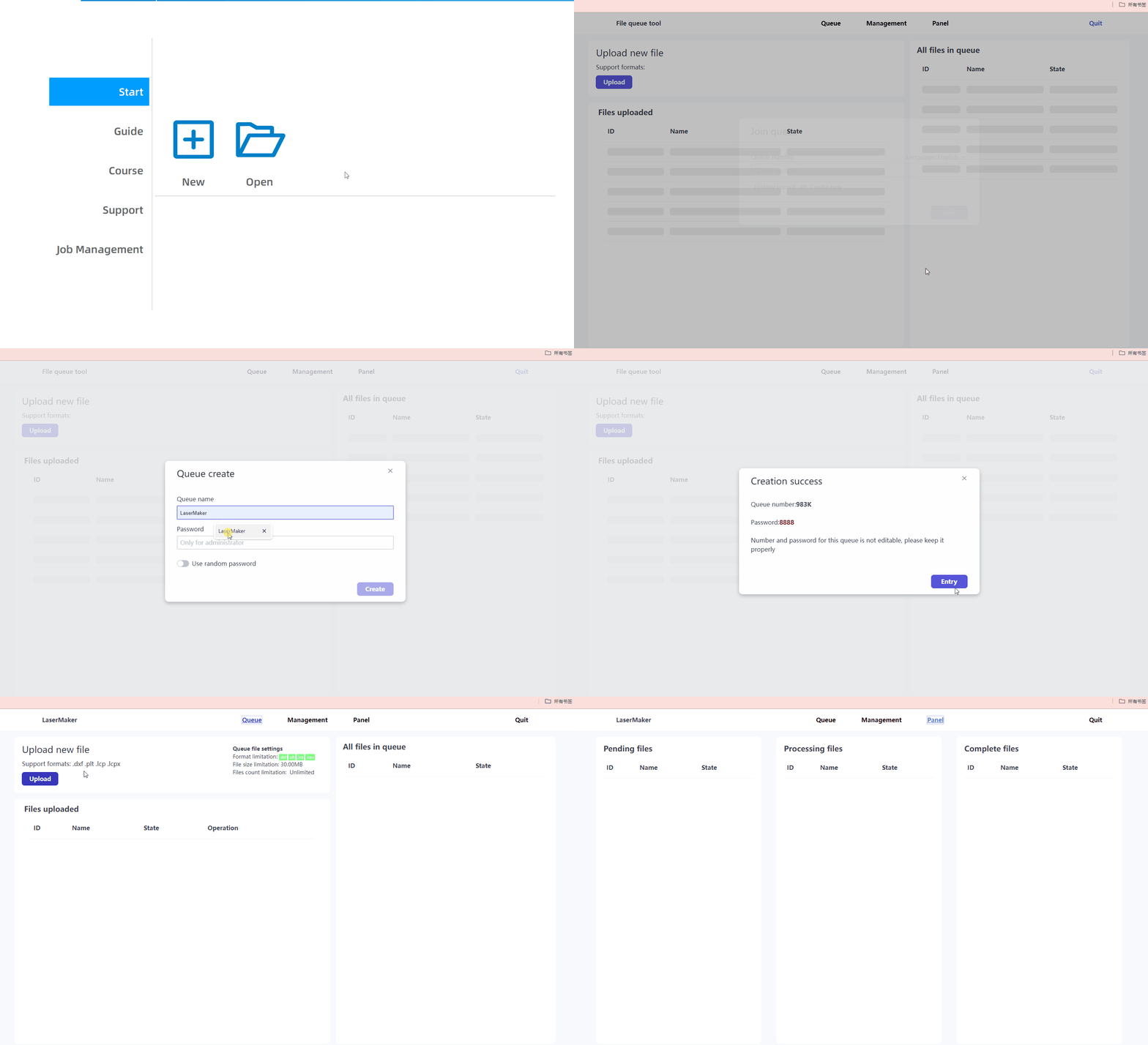
Manage Processing Queues
Click [Home] – [Job Management] – [Enter Now] to enter the job management system. By creating a queue, anyone who joins the queue can upload drawings, and the administrator can manage and process all drawings.
Material Test
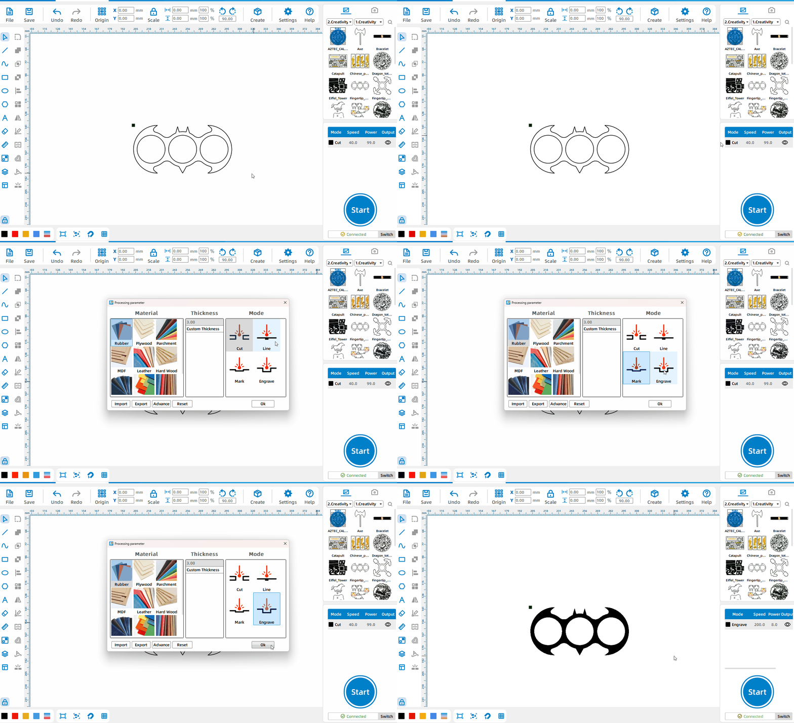
Obtain Optimal Processing Parameters
Left-click the [Material Test], select [Interval] or [Size] mode, set the xy axis quantity, parameters, spacing, whether to use engraving, whether to generate borders and text, and generate a matrix with gradient parameters to observe the processing effect and obtain the best processing parameters.
Auto Typography
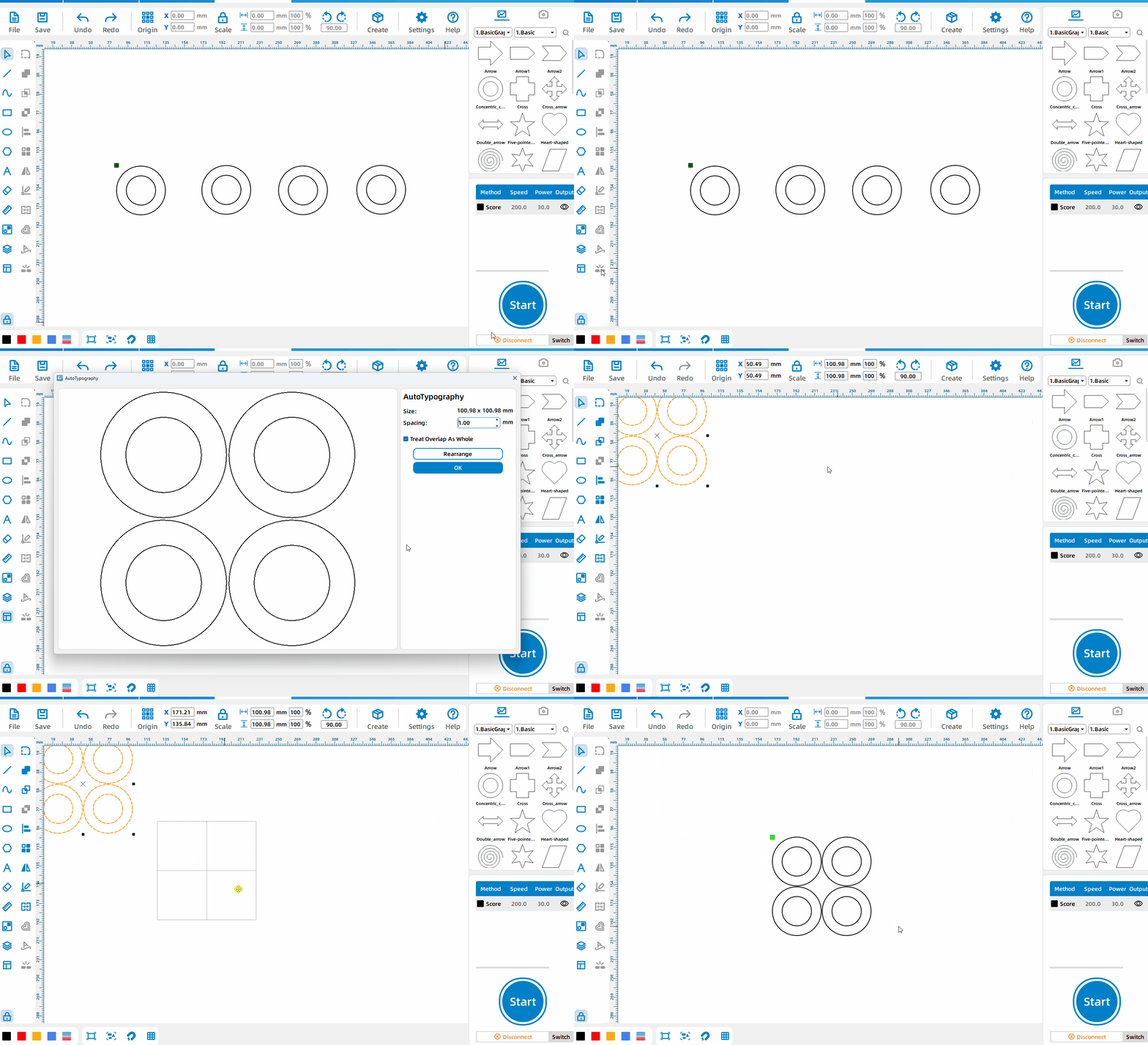
Auto Typography of patterns
After drawing the patterns, left-click the [Auto Typography] to automatically layout the drawings, saving processing materials.
Thickness
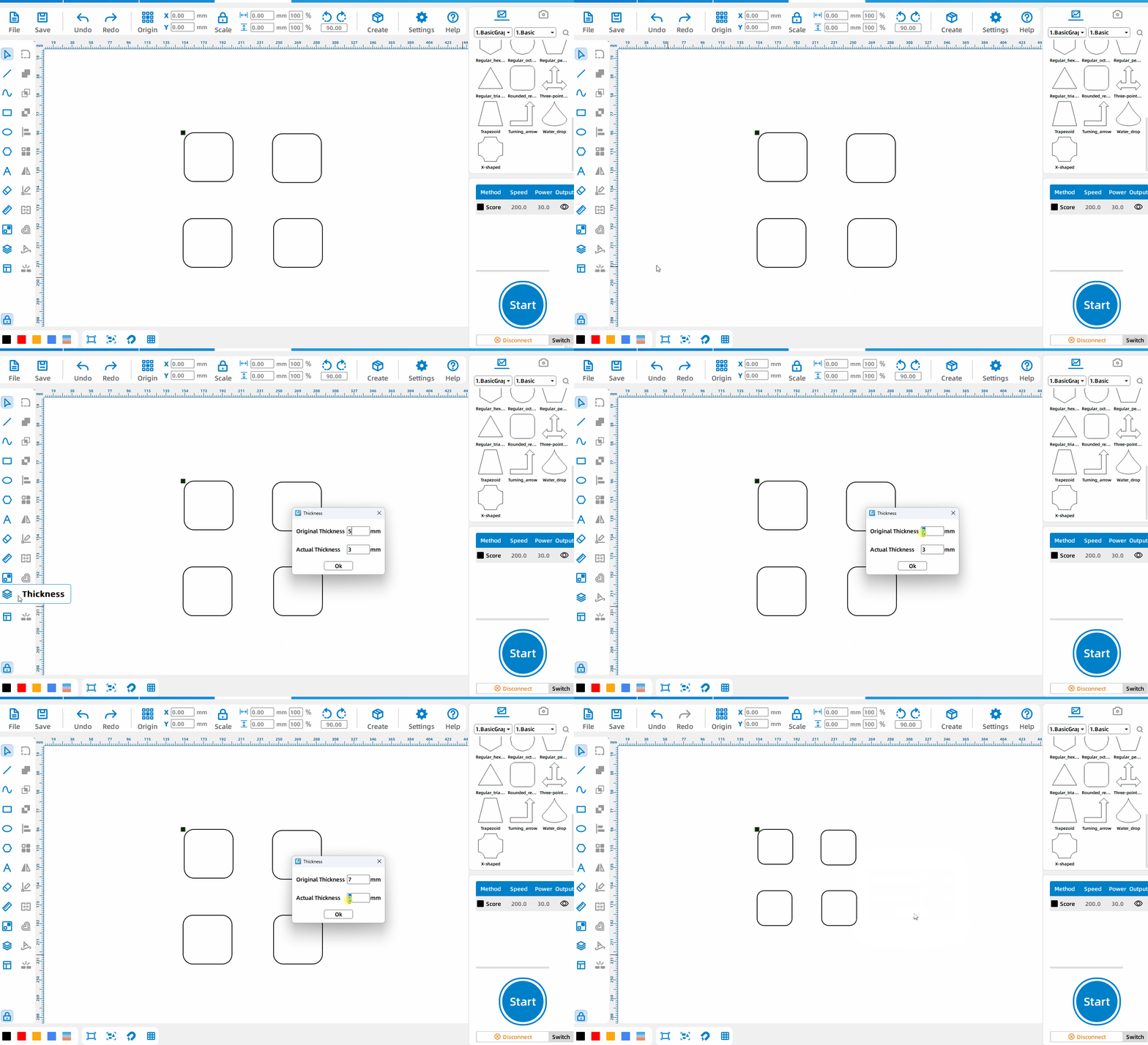
Change the drawing slot size
Left-click the [Thickness] to set the thickness of the original drawing first, then enter the actual thickness currently required.
Rotary
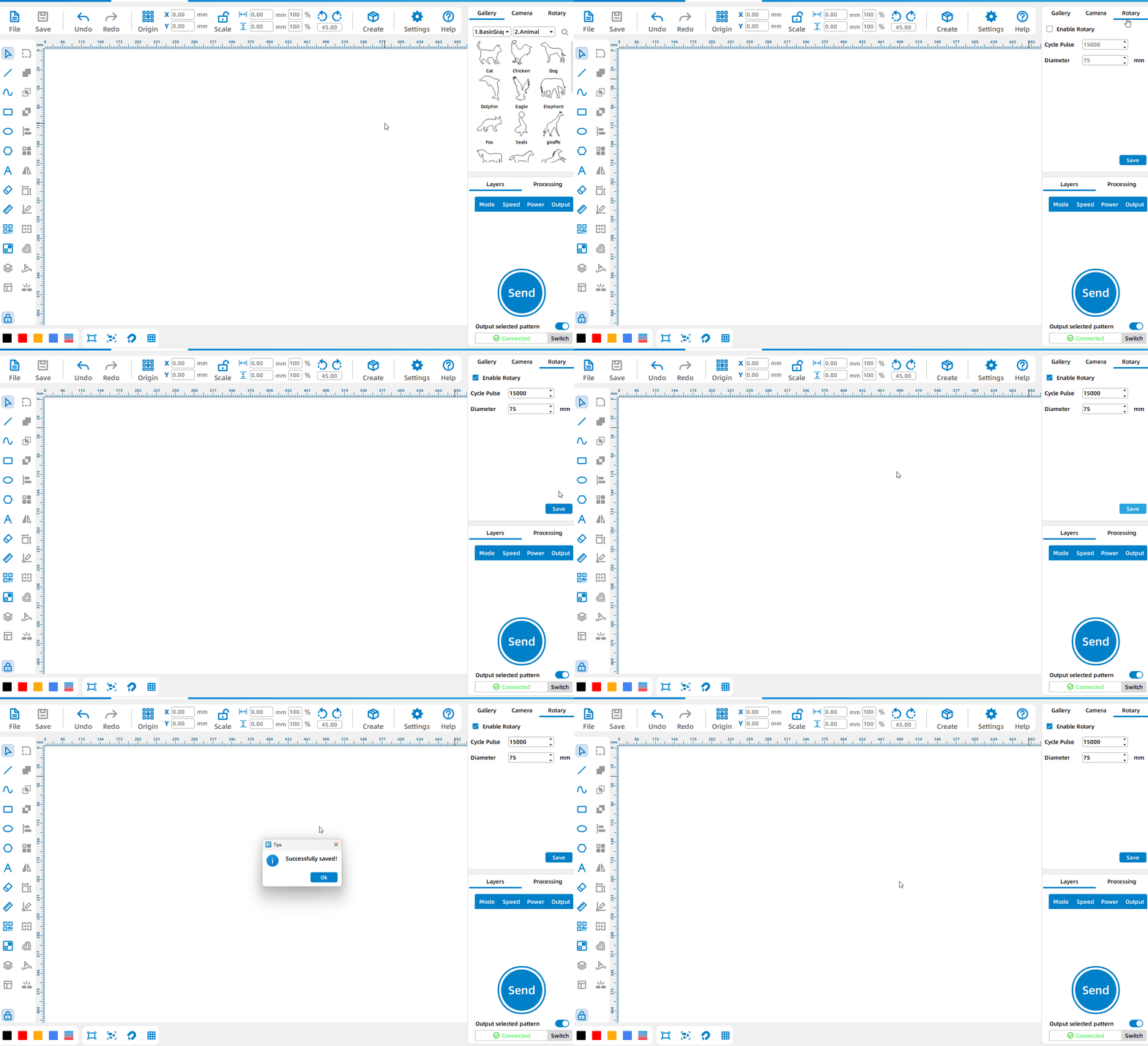
Enable Rotary
Click [Rotary], check [Enable Rotary] and click [OK] to enable the Rotary.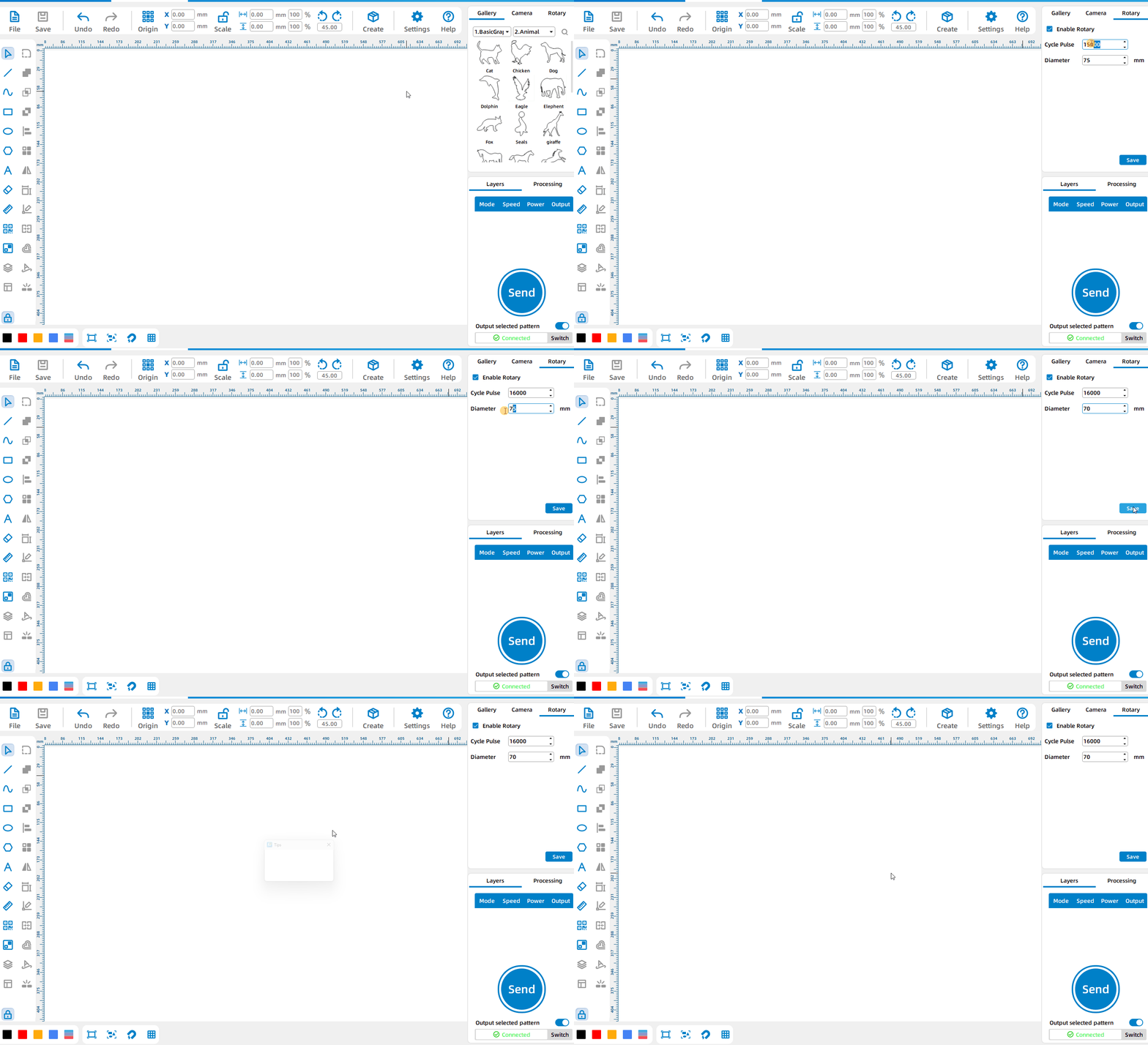
Set the Rotary parameters
After checking [Enable Rotary], you can set cycle pulse and diameter.
Export the Selected Entities
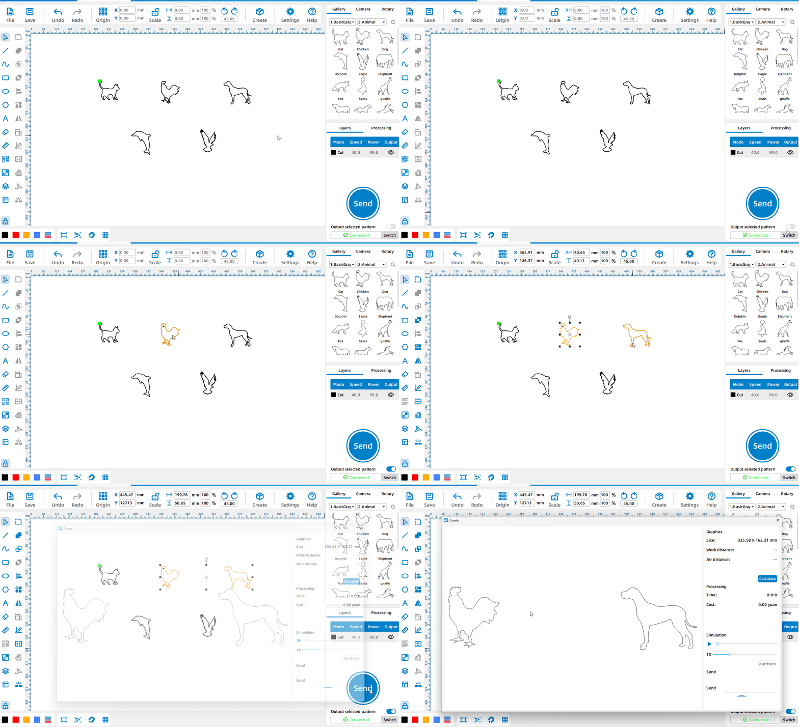
Export only the selected entities
Check [Output Selected Pattern], select the pattern, and you can send the currently selected pattern to the device or directly process the currently selected pattern
Processing Module
Software Licensing
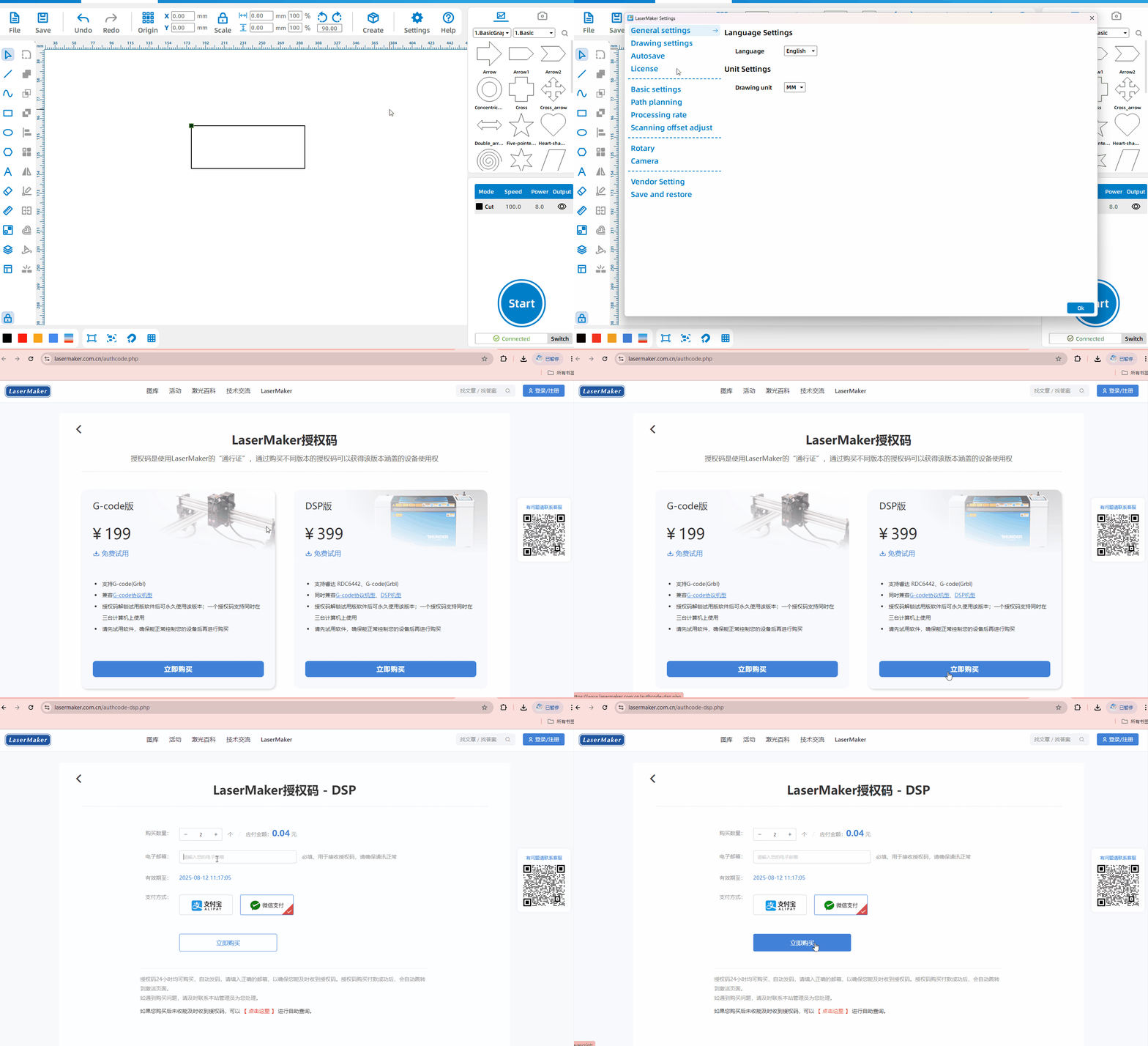
Buy License
Click [Settings] – [License] – [Buy License ] to jump to the official website to bug the license
Activate license
Click [Settings] – [License] to try the free license, or enter the buy license and click [Activate license]
Device Connection
Device Management
Left-click any device and click [Test] to test whether the current device is connected successfully. Click [Delete Icon] to delete the current device from the device list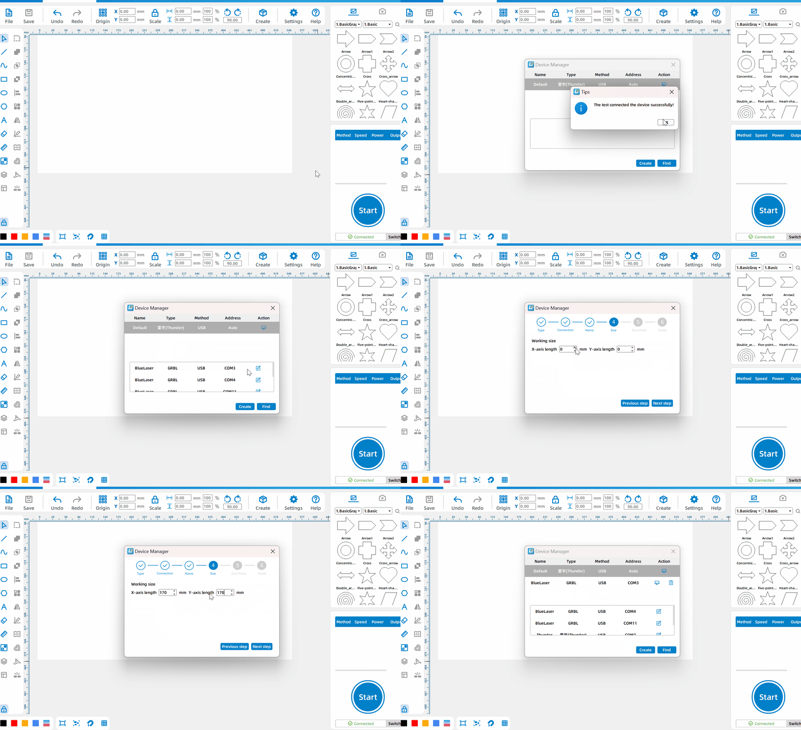
USB Connection
If it is a Thunder laser device, connect the device via USB, and you can process it directly after successful communication; if it is other devices, click [Switch] – [Search], you can edit the found device in the list box, click [Edit], and you can complete adding the device after editing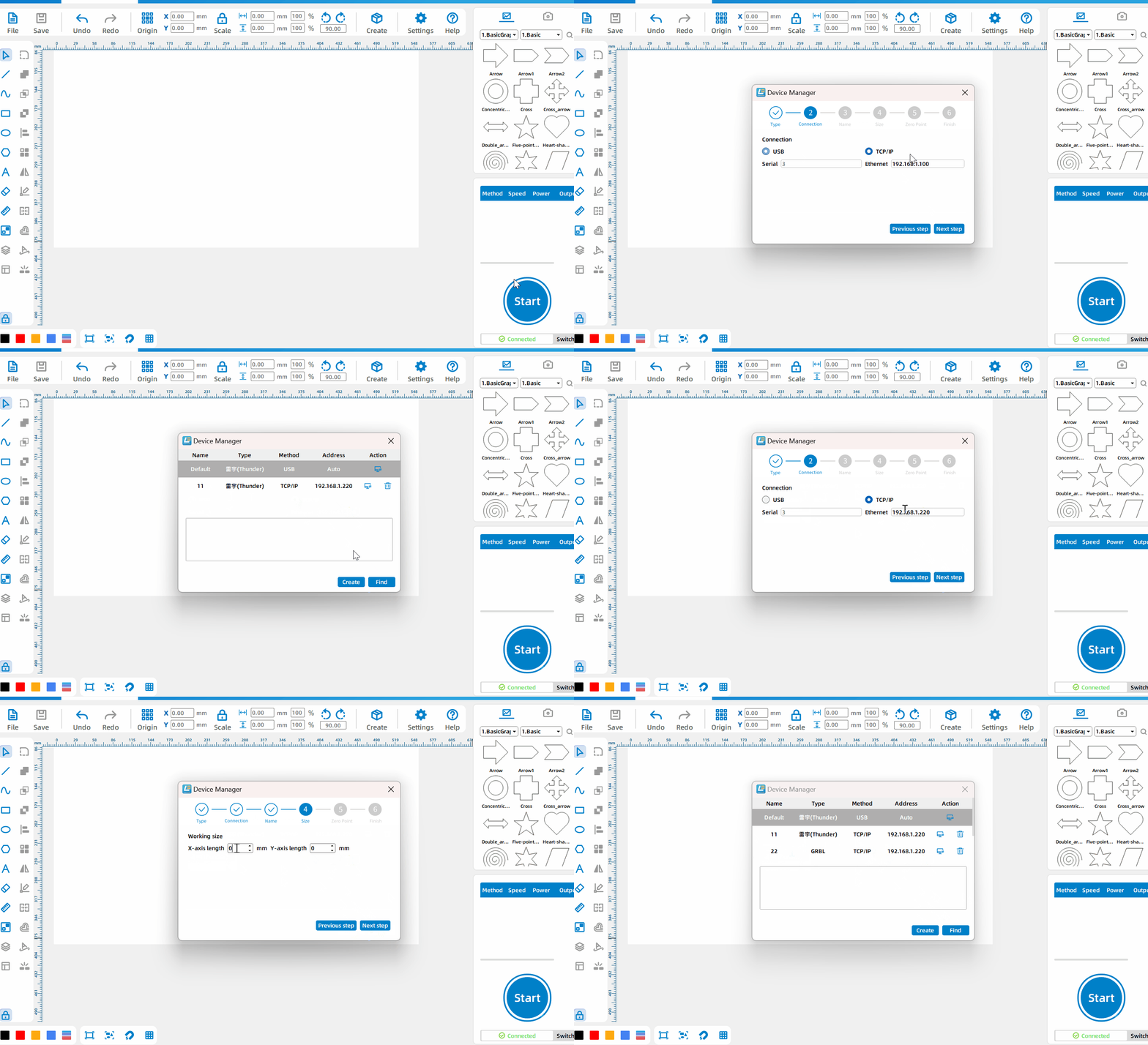
TCP/IP Connection
Click [Switch] – [Create], select the device type. If it is a Leiyu device, you can successfully create it after setting the connection method and device name; if it is other devices, you can successfully create it after setting the connection method, device name, size, and zero point
Processing Parameters
Set Different Layers
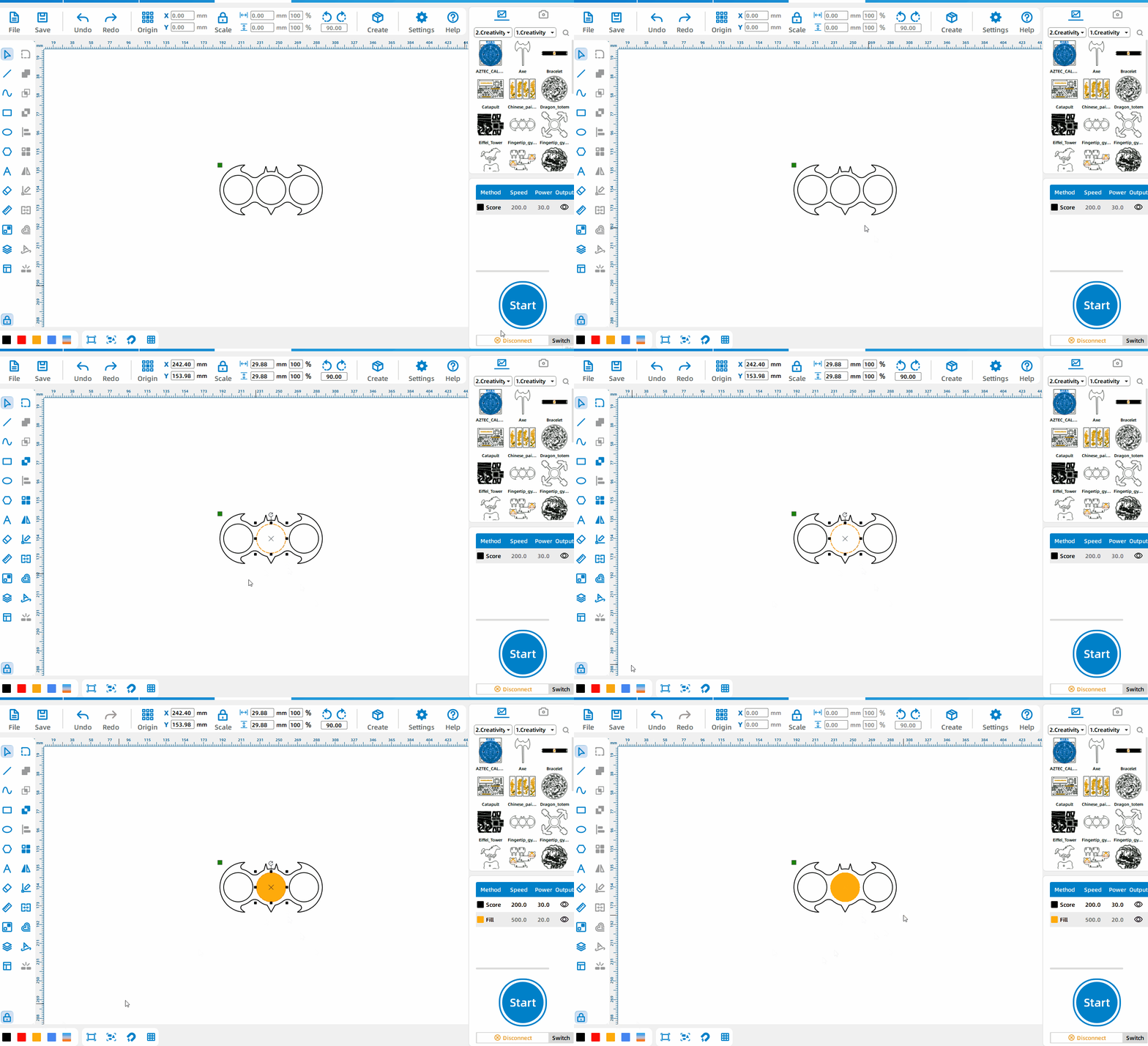
Select the pattern and left-click different colored blocks to set different layers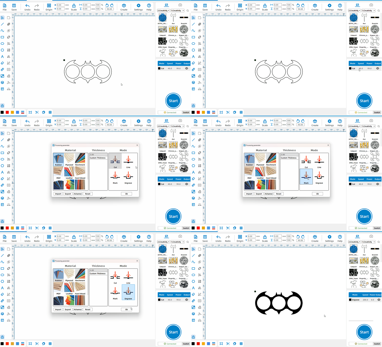
Set Processing Parameters
Double-click any layer to select different material types, material thicknesses, and processing techniques; double-click the processing technique to set the processing parameters
Simulation Creation
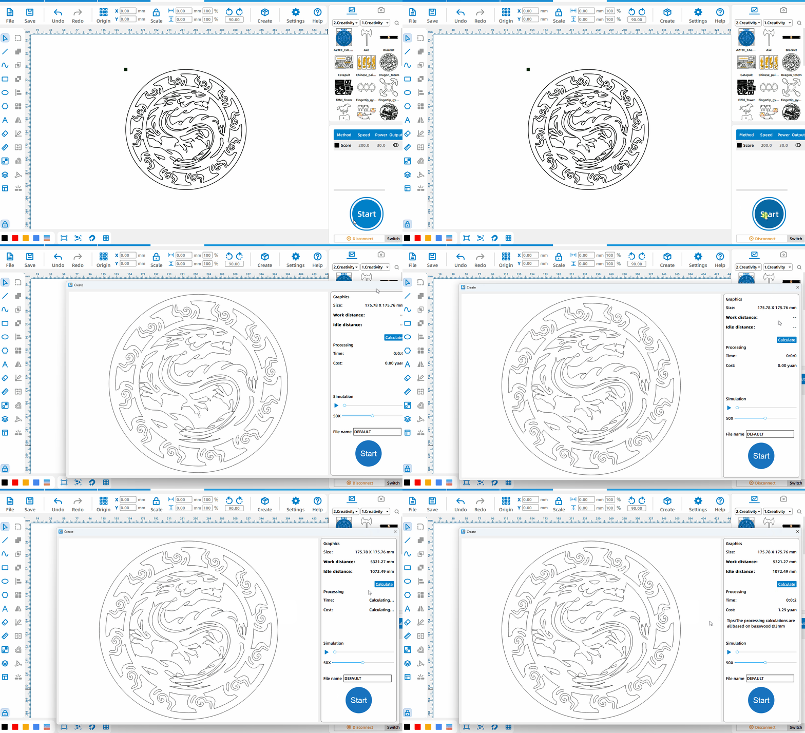
Processing calculation
Click [Start] – [Calculate] to calculate the time and cost required to process the current drawing with 3mm basswood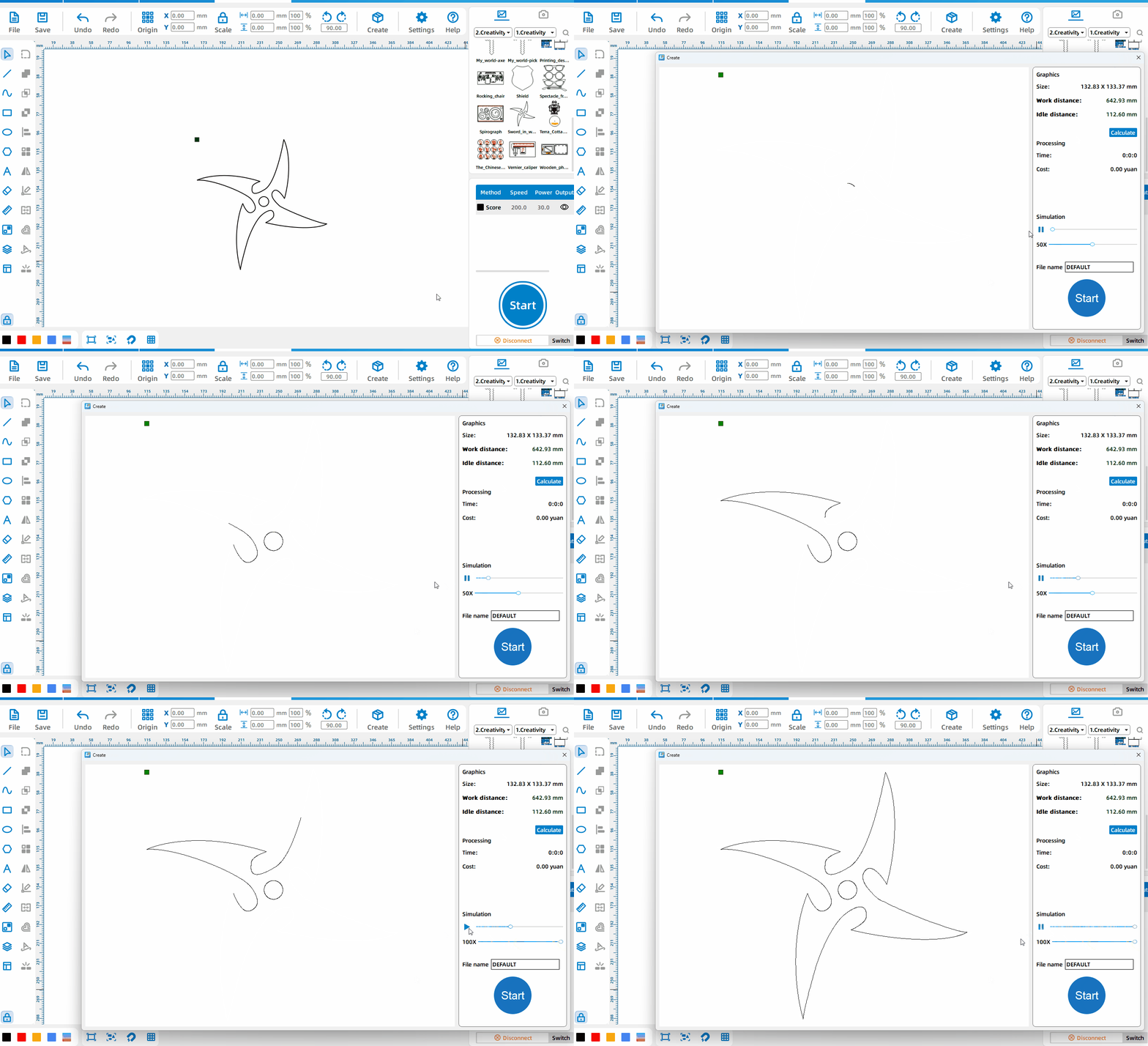
Simulation Processing
Click [Start] – [Simulation] to simulate the actual creation process and results. It supports pausing the simulation, dragging the progress bar and speeding up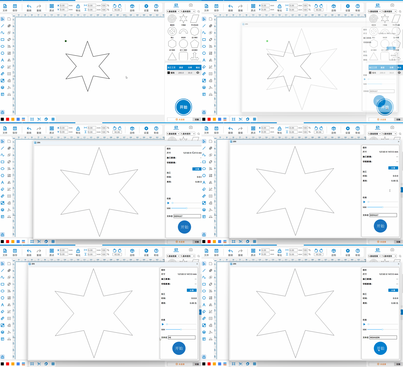
Send File To Device
Click [Start], set the drawing file name, and click [Start] to send the file to the device
Remote Control Processing
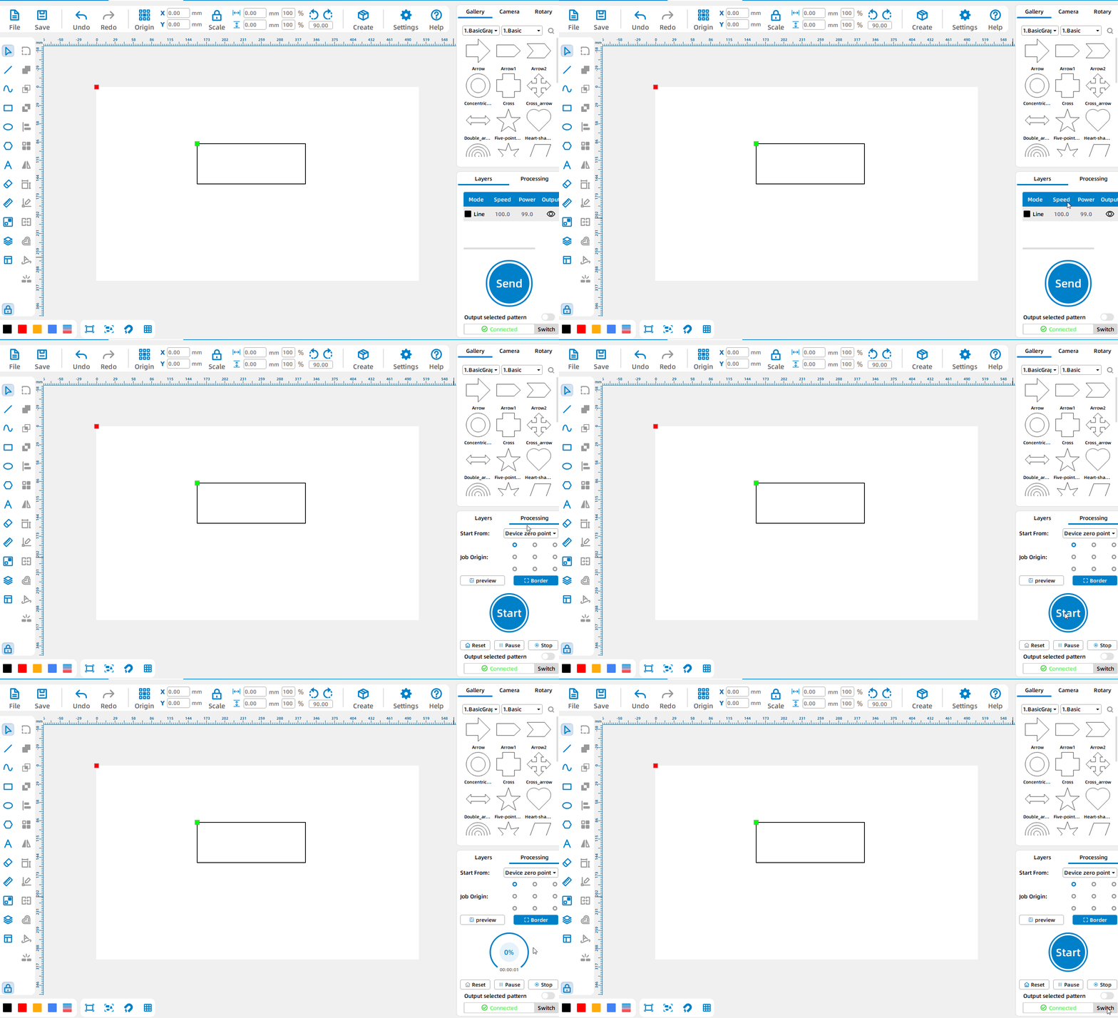
Control processing within the software
After drawing the pattern, click [Control Processing] and then click [Start] to directly process the pattern on the canvas.
.png) International
International
 United States
 Brasil
 Canada
 Costa Rica
 Mexico
 Česká
Česká
 Romania
 Polska
 Ireland
 Portugal
 Lietuva
 Россия
 Deutschland
 Britain
 Україна
 France
 Sverige
 Italia
 Norway
 Denmark
 Ελλάδα
 한국
한국
 中国
中国
 ประเทศไทย
 中国香港
中国香港
 Israel
 中國臺灣
中國臺灣
 India
India
 پاکستان
 پශ්රී ලංකා
 ジャパン
ジャパン
 Australia
 New Zealand
 South Africa